| External diameter (mm) | Length (mm) | Thread diameter | Wrench size (mm) | Attached material thickness (mm) | Drill diameter |
| 8 | 45 | m6 | 10 | 5 | 8 |
| 8 | 60 | m6 | 10 | 20 | 8 |
| 8 | 80 | m6 | 10 | 40 | 8 |
| 8 | 85 | m6 | 10 | 50 | 8 |
| 8 | 100 | m6 | 10 | 60 | 8 |
| 10 | 50 | m8 | 13 | 5 | 10 |
| 10 | 55 | m8 | 13 | 6 | 10 |
| 10 | 60 | m8 | 13 | 10 | 10 |
| 10 | 80 | m8 | 13 | 25 | 10 |
| 10 | 85 | m8 | 13 | 30 | 10 |
| 10 | 100 | m8 | 13 | 45 | 10 |
| 10 | 110 | m8 | 13 | 55 | 10 |
| 10 | 120 | m8 | 13 | 65 | 10 |
| 10 | 125 | m8 | 13 | 70 | 10 |
| 10 | 130 | m8 | 13 | 75 | 10 |
| 10 | 140 | m8 | 13 | 85 | 10 |
| 12 | 65 | m10 | 17 | 3 | 12 |
| 12 | 70 | m10 | 17 | 5 | 12 |
| 12 | 80 | m10 | 17 | 10 | 12 |
| 12 | 100 | m10 | 17 | 20 | 12 |
| 12 | 110 | m10 | 17 | 30 | 12 |
| 12 | 120 | m10 | 17 | 40 | 12 |
| 12 | 130 | m10 | 17 | 50 | 12 |
| 12 | 140 | m10 | 17 | 60 | 12 |
| 12 | 150 | m10 | 17 | 70 | 12 |
| 12 | 160 | m10 | 17 | 80 | 12 |
| 16 | 75 | m12 | 19 | 5 | 16 |
| 16 | 100 | m12 | 19 | 10 | 16 |
| 16 | 110 | m12 | 19 | 20 | 16 |
| 16 | 130 | m12 | 19 | 40 | 16 |
| 16 | 150 | m12 | 19 | 60 | 16 |
| 16 | 220 | m12 | 19 | 120 | 16 |
| 20 | 100 | m16 | 24 | 10 | 20 |
| 20 | 110 | m16 | 24 | 15 | 20 |
| 20 | 140 | m16 | 24 | 40 | 20 |
| 20 | 150 | m16 | 24 | 50 | 20 |
| 20 | 160 | m16 | 24 | 60 | 20 |
| 20 | 200 | m16 | 24 | 100 | 20 |
Mounting options
| Anchor diameter | 8 | 10 | 12 | 16 | 20 |
| Min. hole depth (mm) | 50 | 60 | 70 | 80 | 90 |
| Diameter of hole in part (mm) | 9 | 11 | 13 | 17 | 21 |
| Min. base thickness (mm) | 70 | 80 | 90 | 100 | 120 |
| Critical edge distance (mm) | 55 | 65 | 70 | 80 | 85 |
| Critical axial distance (mm) | 60 | 70 | 75 | 90 | 95 |
| Tightening torque in concrete (Nm) | 8 | 25 | 40 | 50 | 80 |
| Tightening torque in brick (Nm) | 4 | 12,5 | 20 | 25 |
Design pullout and shear force
| Concrete B20 | |||||
| Anchor diameter | 8 | 10 | 12 | 16 | 20 |
| Pull-out force N (kN) | 1,4 | 2,1 | 2,8 | 4,2 | 5,6 |
| Shear force Q (kN) | 2,5 | 4,5 | 7,3 | 8,8 | 10,5 |
| Brick M150 | ||||
| Anchor diameter | 8 | 10 | 12 | 16 |
| Pull-out force N (kN) | 0,5 | 0,6 | 0,8 | 0,9 |
| Shear force Q (kN) | 1 | 1,2 | 1,6 | 1,8 |
Installation diagram
- Drill a hole
- Clear the hole from dust
- Install the anchor through the part
- Screw in the anchor
Anchor bolts are in demand during installation work. The products are compatible with socket and open-end wrenches and can be used outdoors or indoors.
Anchors are fixed in concrete, asphalt, rock and masonry. They form a reliable connection that is resistant to mechanical, temperature and chemical influences.
The fastener consists of:
- metal sleeve;
- hexagonal pommel;
- spacer element;
- bearing rod.
Products are sold in polymer, cardboard and wooden containers. The delivery set contains a quality certificate and a certificate of conformity. The packaging format is determined by the manufacturer and depends on the size and quantity of products.
How does an anchor fastener with a nut work?
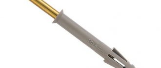
Taking into account the fact that this fastening mechanism must hold quite heavy elements, it was carefully thought out and redesigned. The main structural element in it is a spacer pin, which has a cone shape at one end, and a metric thread is cut at the other end, onto which a nut is screwed. The entire length of the stud, except for the threaded part, is fitted with a special metal sleeve with slots.
This device works on the principle of “expansion”, that is, when we start to tighten the nut, the cone-shaped end enters the sleeve and expands it in the hole. A distinctive feature is that such an anchor has a cast pin, which is much stronger than other anchor structures. Well, and, of course, we forgot to mention the nut and, without fail, the lock washer, which are screwed on from the thread side. The washer does not allow the nut to go deeper into the hole when tightening.
In some cases, during fastening, installers use a second washer as an additional lock, which closes the hole at the installation site, but this approach depends on the specific installation conditions.
The scope of application of such fasteners can be quite different: from the installation of stair railings to heavy metal structures. The most popular application today is the installation of brackets for air conditioning. The device itself has quite a decent weight, so the use of such a mount is completely justified.
Anchor bolt with nut - weight, dimensions: what does GOST tell us?
Since all fasteners are complex installation products, they all have appropriate technical documentation. It is from such documents that we can find out technical parameters if necessary. For example, when choosing this or that fastener, we want to know whether the anchor fastening will withstand a weight of 100 kilograms or not. Thanks to the fact that there is documentation, we will receive an answer to our question.
The smallest anchor, whose dimensions are 5x6.5x18 mm, according to the manufacturer's stated characteristics, is capable of withstanding a pullout load of up to 800 kgf.
To make it clearer, kgf is the designation of kilogram/force, where the calculation takes into account the mass of one kilogram and the force with which this kilogram exerts pressure on the scale. Further calculations are quite simple, 1 kgf is equal to approximately one kilogram of any object, based on this, such an anchor will support a product weighing 800 kilograms.
Also, absolutely any bolt has a corresponding GOST, which divides all fastening structures into varieties according to their ability to withstand a certain load, the size and diameter of the fastening element. On large construction sites, such documentation helps in the selection of fastening elements and the purchase of appropriate materials.
Operating conditions for bolts GOST 24379.1-2012
- Design bolts - bolts that absorb loads arising during the operation of building structures or during operation of equipment.
- Structural - bolts intended for fastening building structures and equipment, the stability of which against overturning (lighting supports) or shifting is ensured by the own weight of the structure or equipment. Structural bolts are intended for straightening building structures and equipment during their installation and to ensure stable operation of structures and equipment during operation, as well as to prevent their accidental displacement.
Technical characteristics of anchor bolts
Technical documentation recommends installing such fastenings in solid solid materials, such as concrete, solid brick, natural stone. In each individual case, we must choose a bolt and nut whose dimensions will provide us with high-quality fastening. But it is worth remembering that during installation, when tightening the nut, the stud moves forward a certain distance; as a result, sometimes this length creates an obstacle when installing the products that we are fastening.
Today in stores you can find fasteners of almost any length, for various types of tasks. As a rule, the line of anchor fastenings begins with a stud size of 18 millimeters.
The longest fastener reaches 400 millimeters in net size of the fastening pin. Accordingly, depending on the length, we also have different diameters; this value is calculated by the diameter of the sleeve for which the hole is drilled.
The diameter of the bushing usually starts from 6.5 millimeters, this is, as a rule, the smallest anchor; gradually, as the length increases, the diametrical value also increases; on the longest fastening, the bushing can be 20 millimeters in circumference, and such fasteners can withstand quite significant loads. If you are interested in the holding force of such fasteners, you can find it out from the technical documentation, we talked about it earlier.
When choosing an anchor, always consider the thickness of the surface on which the installation will be made. Long does not mean durable, and besides, you risk getting a through hole, which is undesirable when installing the fastener.
Climatic region for installing foundation bolts
| steel grade | Regulatory document | Steel category for climatic construction area according to GOST 16350 | ||
| II1, II5, etc. | I2, II2 and III3 | I1 | ||
| St3kp*5 | GOST 535 | 2* | — | — |
| St3ps,St3sp | GOST 535 | 2 | 4** | — |
| 20 | GOST 1050 | + | — | — |
| 09G2S | GOST 19281 | 6*4 | 6 | 6*** |
| 10G2S1 | GOST 19281 | 6*4 | 6 | 6*** |
* For fastening building structures and equipment. ** For bolts up to 24 mm in diameter. *** For bolts with a diameter of up to 48 mm. *4 For bolts with a diameter of 56 mm or more; for smaller diameters - during a feasibility study. *5 For structural bolts only. Note - The “+” sign means that the steel category and requirements for it should not be indicated in the project; the sign “-” means that this grade of steel should not be accepted in the specified climatic region.
40X structural chromium alloy steel with a Brinell hardness of 179 MPa and a short-term tensile strength of 980 MPa in its production
Reinforced version - double-spacer fastener
Due to the fact that consumer requirements are constantly growing, and there is a need for the installation of fairly heavy structures, it was decided to slightly modify the fasteners. This is how a modified product appeared on the building materials market - an anchor bolt with a double-spacer nut. This technology has made it possible to sufficiently increase the holding force of such fastenings.
The design itself is the same pin, but in this case two bushings are used as a holding mechanism, one of which is wedge-shaped and fits into the second bushing. Thus, by tightening the nut, we increase the holding properties, evenly distributing the force along the entire length of the fastener. The double-spacer anchor with a ring uses the same technology in its design, and, as practice shows, quite successfully.
This modified fastening is used mainly in production, but not only in the construction environment. For example, very often this mounting element is used to fasten machine tools in workshops.
Usually, during operation, the machine creates a certain vibration, which, as a rule, is not needed, and if previously the machine was simply attached to the floor using concrete, today the easiest way is to use a universal mount and get rid of unwanted vibration during operation.
Types and design of foundation bolts
| Bolt type | Execution | Name of foundation bolt | Parts and assembly units of the kit | Qty |
| 1 | 1 | Curved bolts - with a hook-shaped bottom | 1 Hairpin (item 1) | 1 |
| 2 Washer | 1 | |||
| 3 Nut according to GOST 5915 | 2 | |||
| 2 | 1 Pin (item 2) | 1 | ||
| 2 Washer | 1 | |||
| 3 Nut according to GOST 5915 | 2 | |||
| 2 | 1 | Bolts with anchor plate - with a bottom made of metal plate | 1 Hairpin (item 3) | 1 |
| 2 Anchor plate (item 11) | 1 | |||
| 3 Washer | 1 | |||
| 4 Nut according to GOST 5915 | 4 | |||
| 2 | 1 Pin (pos. 4) | 1 | ||
| 2 Anchor plate (item 11) | 1 | |||
| 3 Washer | 1 | |||
| 4 Nut according to GOST 10605 | 4 | |||
| 3 | 1 Pin (pos. 4) | 1 | ||
| 2 Anchor plate (item 13) | 1 | |||
| 3 Washer | 2 | |||
| 4 Nut according to GOST 10605 | 3 | |||
| 3 | 1 | Composite bolts - the lower part of which is placed in concrete, and the upper part is connected to a special coupling | 1 Hairpin (item 3) | 1 |
| 2 Pin (pos. 5) | 1 | |||
| 3 Clutch (pos. 13) | 1 | |||
| 4 Anchor plate (item 11) | 1 | |||
| 5 Washer | 1 | |||
| 6 Nut according to GOST 5915 | 4 | |||
| 2 | 1 Pin (pos. 4) | 1 | ||
| 2 Pin (pos. 5) | 1 | |||
| 3 Clutch (pos. 13) | 1 | |||
| 4 Anchor plate (item 11) | 1 | |||
| 5 Washer | 1 | |||
| 6 Nut according to GOST 10605 | 4 | |||
| 4 | 1 | Removable bolts - consisting of a lower race and a threaded stud | 1 Hairpin (item 5) | 1 |
| 2 Anchor fittings (item 14, version 1) | 1 | |||
| 3 Washer | 1 | |||
| 4 Nut according to GOST 5915 | 2 | |||
| 2 | 1 Pin (pos. 6) | 1 | ||
| 2 Anchor fittings (item 14, version 2) | 1 | |||
| 3 Washer | 1 | |||
| 4 Nut according to GOST 10605 | 2 | |||
| 3 | 1 Pin (pos. 6) | 1 | ||
| 2 Anchor fittings (item 14, version 3) | 1 | |||
| 3 Washer | 1 | |||
| 4 Nut according to GOST 10605 | 2 | |||
| 5 | — | Straight bolts - fastened into pre-made holes with silicone or epoxy glue | 1 Pin (pos. 7) | 1 |
| 2 Washer | 1 | |||
| 3 Nut according to GOST 5915 | 2 | |||
| 6 | 1 | Tapered end bolts - installed into a finished foundation using an expanding collet | 1 Pin (pos.  | 1 |
| 2 Expanding collet (item 15) | 1 | |||
| 3 Washer | 1 | |||
| 4 Nut according to GOST 5915 | 2 | |||
| 2 | 1 Pin (pos. 9) | 1 | ||
| 2 Conical bushing (pos. 16) | 1 | |||
| 3 Washer | 1 | |||
| 4 Nut according to GOST 5915 | 2 | |||
| 3 | 1 Pin (pos. 10) | 1 | ||
| 2 Washer | 1 | |||
| 3 Nut according to GOST 5915 | 2 |
How to properly install an anchor bolt with a nut - step-by-step diagram
Step 1: Anchor Hole Diameter
Before drilling a hole for the fastening, you need to select a concrete drill for a hammer drill of the required diameter. In this case, first of all, be guided by the dimensions of your mount. It is under no circumstances recommended to drill a hole if the bushing does not fit into it. It is better to go through the same diameter drill again, and the hole will become a little larger. If you drill out the fastening point with a drill of a larger diameter, the bushing can freely “walk” in it, while the spacer mechanism simply cannot perform its holding functions.
Step 2: Clear the mounting area of debris
It is no secret that after drilling, debris remains in the finished hole after using a hammer drill. It is these crumbs and dust that interfere with the installation of the bolt at the installation site. It is especially difficult to install a double-spacer mechanism into an uncleaned hole; such fasteners have a sleeve that is slightly wider than usual. Therefore, before installation, thoroughly clean the hole; if necessary, use a construction or household vacuum cleaner.
Step 3: Correct installation of heavy elements
After you have inserted the bolt into the hole, do not rush to mount your device while tightening the nuts; there is a more practical solution. After installing the anchor, without hanging the product, tighten the bolt with a wrench until it stops. Tightening must be carried out until the pin opens the bushing, and the fastening, so to speak, assumes operating mode. After this, you can place the nut on the studs, which are already firmly held in the mounting hole, install the device, and calmly tighten it with the nuts.
Source
Bolt Load Calculation
The bolt head markings usually contain the following information:
- manufacturer's mark (JX, THE, L, WT, etc.);
- strength class;
- arrow “counterclockwise” (if left-hand thread).
The first number indicates the nominal tensile strength (tensile strength): 1/100 MPa (1/100 N/mm²; ~1/10 kg/mm²). Example: (strength class 9.8) 9*10=900 MPa (900 N/mm²; 91.71 kg/mm²).
The second number indicates the percentage of yield strength to tensile strength (tensile strength): 1/10%. Example: (strength class 9.8) 9*8=720 MPa (720 N/mm²; 73.37 kg/mm²).
The yield strength value is the maximum permissible working load of the bolt, above which irreversible deformation occurs. When calculating the load, 1/2 or 1/3 of the yield strength is used, with a double or triple safety margin, respectively.
According to the current international classification, high-strength bolts include products whose tensile strength is greater than or equal to 800 MPa (800 N/mm²; 81.52 kg/mm²). Accordingly, starting from 8.8 for bolts and 8 for nuts.
Examples of material flow
An example would be a common kitchen fork. By bending it in one direction, you can get a completely different object, which means its fluidity is disrupted, which leads to deformation. In this case, the material only deformed, but did not break, which indicates a high degree of elasticity of the steel. Conclusion: maximum strength is much higher than yield.
Other kitchen equipment, such as a knife, will break if you try to change its shape. Conclusion: the knife has the same fluidity and strength; such a product can be called fragile, despite the fact that it is made of steel.
A similar practical example would be screwing in a nut: the bolt itself increases in length only after a certain amount of action is applied to it. If the outcome of the experiment is unfavorable, the thread on the fastener may break.
The percentage of elongation is an average indicator that demonstrates the length of the deformed part before the onset of failure. Figuratively, we can call this kind of bolts flexible, meaning precisely the ability to elongate.
The technical terminology for this is quite simple: elongation is nothing more than the percentage of increase in a sample compared to its original size.
