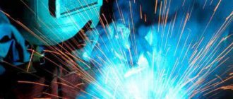
This article will go We are talking about semi-automatic welding in a protective gas environment. This type of welding is in demand during the production of metal structures and products in a workshop, stationary. But now there are also mobile semi-automatic welding machines with small gas cylinders. Of course, semi-automatic welding on the street has a number of disadvantages and limitations, we will talk about them below.
As a rule, PA welds metal structures and products made of ferrous and non-ferrous metals. In order to use this type of welding, you need to know the features of use. Select the right welding wire, shielding gas, components and protective equipment.
Advantages of semi-automatic welding
It’s the 21st century, and manual arc welding with a consumable electrode has been replaced by semi-automatic welding in a shielding gas environment. Now, I want to talk about the advantages of semi-automatic welding over RDS. And there are quite a few of them...:
- High performance. It’s not for nothing that this type of welding is semi-automatic. That is, half of the work is done for the welder by the welding machine (Supplying shielding gas, feeding welding wire (these are the main functions)). But modern semi-automatic welding machines can do much more...
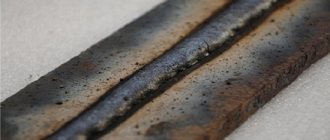
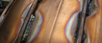
- Aesthetics of the weld. There is no need to knock off the slag crust from the seam; accordingly, the area where welding work is carried out is less contaminated. The seam is neat and even.
- Easy to learn. It is much easier to learn how to use PA than RDS. In order to perform semi-automatic welding with sufficient quality and speed, you need to spend much less time on training...
- Ability to weld very thin metal. That is, a semi-automatic machine can weld metal workpieces with a thickness of 1 mm or even less. Achieving the same results with an electrode is much more difficult, and those who are capable of performing such work can be counted on one hand.
- Smaller heat affected zone. This means that when welding, the likelihood that the product or structure will move is much lower.
Welding speed
In semi-automatic welding, the speed of movement of the torch is set by the welder. It is necessary to choose a speed at which high-quality formation of the weld is obtained. Thick-walled structures are usually welded at high speed, forming narrow seams. At high welding speeds, it is necessary to ensure that the end of the wire and weld metal does not oxidize through the exit from the gas protection zone. At low welding speeds, the weld width increases due to the expansion of the weld pool. The ability to form pores increases.
Disadvantages of semi-automatic welding
Semi-automatic is certainly not ideal and has a number of disadvantages. Which we, as well as the advantages, compare with manual arc welding.
- Limited mobility. Namely, with a semi-automatic machine, it will be problematic to perform welding work in a confined space. That is, if there is a need to weld something in some small tank, to which access is limited.
- Weather. That is, when you need to weld outdoors, you must take into account the presence of wind. Wind can reduce the quality of the weld by blowing away the shielding gas during welding. In order to avoid this, it is necessary to increase the operating gas pressure. Thus, the gas escaping from the burner nozzle will be able to withstand the wind and fulfill its direct duties.
- Relatively high cost. The cheapest semiautomatic welding machine costs an order of magnitude higher than the cheapest welding inverter. And also, for the PA welding process itself, you will need gas and welding wire, which also costs money, but for RDS only electrodes.
Not surprisingly, there are pros and cons. Without a doubt, a semi-automatic machine is 100% suitable for stationary production of metal structures or products.
Semi-automatic welding device
Like any other equipment, a semi-automatic welding machine has a specific device and consists of several components. This is what we will talk about now.
What does a semi-automatic welding machine consist of?
Semi-automatic welding cannot be possible without the presence of the elements listed below.
- Main building
- Welding sleeve.
- Welding torch
- Gas cylinder with reducer and hoses
Main building, device.
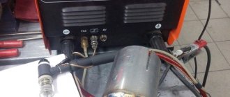
The main building, that is, the semi-automatic welding machine itself. Contains a power source, a wire and gas feed mechanism, as well as a setting device. In some cases, there may be a display showing settings and recommendations.
Pay attention to the useful section of our website - security. Don't forget to visit it!)
Administration
Welding sleeve device
The design of a welding hose for semi-automatic welding is an order of magnitude more complex than a hose for RDS. It contains a channel for transporting shielding gas, a separate channel for welding wire and welding cables for exciting the welding arc. All this together is called a welding sleeve for semi-automatic welding.
Welding torch device
The welding torch consists of several components.
- Spring to prevent welding sleeve from breaking
- Lever
- Button that activates the welding torch
- Mouthpiece (colloquially “gander”)
- Gas guide
- Tip holder with insulating washer
- Current carrying tip
- Conical nozzle
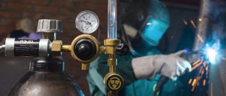
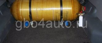
Gas cylinder device
Cylinders for semi-automatic welding in a shielding gas environment are made of seamless pipe and have a rolled bottom. Also, cylinders for carbon dioxide or a mixture of carbon dioxide and argon are equipped with a so-called shoe. It is necessary for storing gas in a vertical position. The cylinders are also equipped with a shut-off valve. Moreover, cylinders cannot be used without a current cylinder passport, which is stamped in the upper part and contains important information.
Gearbox device
The reducer for a gas cylinder for semi-automatic welding is an integral part when welding in a shielding gas environment. Using this device, the operating gas pressure is adjusted.
- Gas inlet valve
- Sealant
- Chamber with adjustment membrane
- Gas supply valve
- Union
- Main building
- Main inlet pressure gauge
- Outlet working pressure gauge
- Shut-off valve
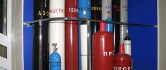
Shielding gas for semi-automatic welding
Since this article is about semi-automatic welding in shielding gases , we should talk about what gases are used and a little about each option. In total, for semi-automatic welding, you can find three options for using gases:
- Carbon dioxide CO2
- Argon Ar
- Helium He
- Nitrogen N
- CO2 + Ar mixture
- Ar + HE mixture
For each option, there are recommendations for use in a particular case:
- Welded structures and products
- Financial opportunities
- Degree of responsibility of the welded joint
As a rule, the main criterion for choosing a gas for semi-automatic welding is the grade of the material being welded .
Carbon dioxide (CO2) is used for welding carbon and low-carbon steels , as well as structural But do not forget that mixtures are also used in these cases ( CO2+Ar , CO2+Ar+HE).
Stainless steel is usually cooked with a mixture of CO2+Ar gases. Such steels, as we know, are also called medical.
As for non-ferrous metals, such as aluminum, copper, titanium, more expensive mixtures are used. Such a mixture is designated as Ar + He. You can also use Argon in its pure form , it should be cheaper... Regarding Copper , it can still be welded in a Nitrogen .
Wire for semi-automatic welding
Semi-automatic welding is performed with a special wire. Its choice depends on several factors.
- Material to be welded (Black, non-ferrous, alloys)
- Thickness of welded metal
- The principle of protecting the weld pool
Types of welding wire for semi-automatic welding
- Copper-plated
- Powder
- For stainless steel
- Aluminum
Each type is used in different situations.
Copper-plated welding wire for semi-automatic machines is most often used. It is used during the production and construction of metal structures, aircraft and shipbuilding, as well as in the automotive industry.
Flux-cored wire is used for semi-automatic welding without shielding gas. The powder that is in the wire and releases the necessary protective gases, but subsequently forms a slag crust.
Stainless steel wire is used for welding stainless steels.
Aluminum welding wire is excellent for welding Aluminum and Aluminum alloys.
In addition, the welding wire may differ in diameter. So, there are welding wires of 0.6 mm, 0.8, 1 mm, 1.2 mm…. 2mm _ The choice of welding wire diameter directly depends on the thickness of the metal being welded . And according to the thickness of the welding wire, a suitable copper tip is selected, which supplies voltage to the wire to excite the welding arc.
Selecting automatic submerged arc welding modes
When choosing the parameters of automatic submerged arc welding modes, the thickness of the weld edges, the requirements for the geometric shape and size of the weld, which depend on the depth of metal penetration during welding, as well as the width of the weld, are taken into account.
When choosing welding modes, initially select the diameter of the electrode wire based on the thickness to be welded. Next, after choosing the wire diameter, select the welding current value, which depends on the diameter. After this, the feed speed of the electrode wire into the welding zone and the welding speed are determined.
For automatic submerged arc welding, solid electrode wire is used. The wire diameter can be within 1-6mm. The welding current is in the range of 150-2000A. The electric arc voltage is 22-55V. Approximate modes of automatic submerged arc welding can be selected from the table below:
Material to be welded
| Metal thickness, mm | Seam type | Edge shape | Gap, mm | Electrode diameter, mm | Current strength, A | Voltage, V at current: | Welding speed, m/h | ||
| variable | constant (reverse polarity) | ||||||||
| Welding of low-carbon steels, welding of medium-alloy steels and welding of high-alloy steels | 3 | Unilateral | Without cutting | 0-1,5 | 2 | 250-500 | 28-30 | 26-28 | 48-50 |
| 5 | Unilateral | Without cutting | 0-2 | 2 | 400-450 | 28-30 | 26-28 | 38-40 | |
| 10 | Unilateral | Without cutting | 2-4 | 5 | 700-750 | 34-38 | 30-34 | 28-30 | |
| 10 | Bilateral | Without cutting | 1-3 | 5 | 650-700 | 34-38 | 30-34 | 32-34 | |
| 20 | Unilateral | Without cutting | 5-7 | 5 | 950-1000 | 40-44 | 32-36 | 18-20 | |
| 20 | Bilateral | Without cutting | 2-4 | 5 | 750-800 | 38-42 | 32-36 | 22-24 | |
| 30 | Bilateral | Without cutting | 6-8 | 5 | 950-1000 | 40-44 | — | 16-18 | |
| 6 | Unilateral | V-shape, 60° | — | 3 | 250-280 | — | 30-32 | 25-28 | |
| 10 | Bilateral | V-shape, 60° | — | 3 | 350-380 | — | 30-32 | 17-20 | |
| 12 | Bilateral | V-shape, 60° | — | 5 | 500-550 | — | 30-32 | 30-36 | |
| Welding titanium and its alloys | 4 | Unilateral | — | — | 3 | 340-360 | — | 32-34 | 45-55 |
| 8 | Bilateral | — | — | 3 | 350-380 | — | 32-34 | 45-55 | |
| 16 | Bilateral | — | — | 4 | 590-600 | — | 32-34 | 40-50 | |
| Copper welding | 6 | Unilateral | Without cutting | — | 4 | 520-540 | — | 40-42 | 40 |
| 12 | Unilateral | Without cutting | — | 5 | 800-820 | — | 42-44 | 16 | |
Semi-automatic welding modes in a shielding gas environment
Below are the main modes of semi-automatic welding in shielding gases.
To be honest, I don't entirely agree with the table. At the factory where I work, we weld 2, 4 and 5 mm workpieces with 0.8 mm wire. As for setting up the welding machine, each machine has its own settings. The question is individual. But, according to the technology, it is correct as in the table. The choice is yours. If you have any questions, you can always ask them in the comments.
Take a break, watch the video on how to set up a semi-automatic welding machine for welding a profile pipe
Features of using a semi-automatic machine for MIG-MAG welding
SELECTION OF TORCH AND TIPS
The power unit of the semi-automatic welding machine generates a constant welding current. the value of which is regulated and set depending on the welding parameters, the thickness (diameter) of the welding wire and the feed speed of the welding wire into the torch. Electrical contact from the power unit to the welding wire is made directly in the welding torch. Under the influence of the flowing current, the torch heats up and the contact tip in it noticeably expands. Argon welding mixtures have lower thermal conductivity compared to carbon dioxide and heat removal from the torch when working with welding mixtures is worse. This leads to noticeable overheating of the welding torch and, in forced modes, can even cause its destruction (melting of the insulating elements). For the same reason, the welding wire in the torch overheats when working with argon mixtures and, due to expansion, can get stuck in the welding tip. This can lead to uneven feeding of the welding wire into the welding zone and even jamming of the wire in the torch. Therefore, when switching to a welding mixture, it is recommended to use welding torches of higher power and use tips of a slightly larger diameter.
SETTING THE FEEDING MECHANISM
To ensure a stable welding mode, it is necessary to stabilize not only the electrical modes *current and arc voltage), but also the speed of the mechanical feed of the welding wire into the torch. As noted above, if the electric tip is incorrectly selected, the welding wire may jam in the torch. The design feature of most semi-automatic welding machines is that the welding wire is fed into the torch through the feed channel (hose) by pushing the wire forward through the feed rollers installed on the welding machine. An important parameter for setting up a welding machine is adjusting the wire feed tension. If the tension of the feed rollers is weak, the difficulty of passing the welding wire in the torch will lead to the wire slipping between the rollers and destabilizing the speed of its feed into the welding zone (pulling and reducing the feed speed until it stops completely). If the tension on the feed rollers is too high, the passage of the welding wire through the torch may be obstructed, causing the welding wire to become crushed in the feed channel, causing the welding wire to stop flowing into the welding zone. At the same time, too-tight feed rollers cause the wire to flatten and exacerbate the problem of wire passing through the tip in the torch. To prevent this problem, it is recommended to use tips with a non-circular hole (square, triangle, star, etc.)
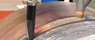
Semi-automatic welding technique in various positions
Semi-automatic welding is quite simple. As you understand, workpieces and parts can be welded in various spatial positions. And for each position, there are its own nuances and features. First, let's look at what welding positions there are.
- Lower
- Ceiling
- Vertical
- Horizontal
- Angular
In the list above, you can familiarize yourself with the existing locations of the joints of the welded parts in space. Simply put, the spatial positions of the future or present seam.
Next, we should familiarize ourselves with the possible types of arrangement of welded joints in relation to the joints to each other.
- Tavrovoe
- Angular
- Overlapping
- Butt
- End
Semi-automatic welding butt joints
When carrying out welding work, the type of connection should be taken into account. So, if you are faced with a butt joint , pay attention to the thickness of the metal. If the metal is thin, from 1 to 3 mm, use a copper backing. With its help, we will prevent metal from dripping, and therefore minimize the risk of burn-through. Moreover, if possible, position the joint vertically and weld it from top to bottom. This makes it easier to weld thin metal. If, during butt welding of parts, the metal thickness is more than 3 mm, but not more than 5 mm, a small gap should be set. A gap of 1-2 mm will be enough for decent penetration. For thicker metal, whose thickness is more than 5mm, it is necessary to cut the edges. Only in this case will it be possible to achieve sufficient penetration of the welded joint.
Have you visited the consumables section yet? Be sure to visit, we have prepared more than one interesting article for you!
Semi-automatic welding of tee and corner joints
T-joints and corner joints if you arrange the parts in such a way that the corner joint is accessible for welding using the so-called “boat”. At the same time, it is necessary to increase the wire overhang by 9-14%. Moreover, the welding arc should be controlled so as not to make undercuts on the walls of the parts being welded.
Semi-automatic welding of lap joints
Overlapping parts with a thickness of 1 to 2 mm are easier to weld with a copper plate placed under them. This way we minimize the chance of burnout. Those parts whose metal thickness is more than 2 mm can be welded without a copper plate. For thicknesses greater than 5mm, it is recommended to weld in several passes.
Semi-automatic welding of horizontal seams
We smoothly move on to semi-automatic welding of horizontal seams . Welding is performed with the torch angle forward. Do not make oscillatory movements when welding thin metal. If you need to weld workpieces made of thick metal, cut the edges.
Vertical seams semi-automatic welding
Welding vertical seams . If the metal is thin, weld from top to bottom. With medium thicknesses, the same thing, from top to bottom, only with oscillatory movements. To weld parts made of thick metal, you should cut the edges and weld from bottom to top, with oscillatory movements.
Semi-automatic welding of ceiling seams
When welding ceiling seams, it is necessary to take into account the thickness of the metal. Thin metal is best welded with a backward angle, and thick metal with the torch angle forward. Also, do not forget about cutting edges with thick metal and oscillatory movements.
Features of semi-automatic welding in shielding gases
Well, we’ve come to the features of semi-automatic welding in shielding gases. First, let's finally define it... Semi-automatic welding is usually called PA or MIG. Such welding is an improved version, even a revolutionary solution. With its help, the quality of welds was improved in some cases. Moreover, work productivity has increased. Now, the same metal structures and products can be produced much faster, with the same quality of seams.
Also, among the features of semi-automatic welding in shielding gases, I would like to include the fact that there is no need to knock the slag off the seam. Which improves the aesthetics of the workplace. And also, during welding, much less combustion products are released. And this increases the health safety of the welder.
Attention! An important topic is safety precautions when performing welding work. Compliance with which is mandatory for everyone!
I would like to draw your attention to a few more features.
- The copper current-carrying tip is selected depending on the diameter of the wire used.
- The wire feed speed depends on the set current and per revolution.
- The operating gas pressure should be carefully adjusted so as not to overdo it. If a lot of gas is exposed, the welding will feel much harsher, and the seam will not be as beautiful and high-quality.
- When performing work outdoors, take into account the presence and strength of wind. If wind is present, add operating gas pressure. Or cover the welding area with a screen. Otherwise, the wind will blow the gas away. As a result, the weld pool will remain unprotected. And these are pores and other defects in the weld.
- Don't forget to clean the nozzle and tip of any dirt. Otherwise, problems with the quality of the seam will arise.
- The semi-automatic machine really does not like welding on painted surfaces, as well as rusty and dirty ones.
Conclusion
Semi-automatic gas shielded welding is an excellent solution for stationary work in a workshop. Provides high productivity and seam quality. If you have decent skills, there is no need for additional seam stripping.
The ease of mastering semi-automatic welding arouses the interest of amateurs. And it’s not in vain. After all, PA is perfect for garage and household work.
Don't forget to rate the article, repost and, if necessary, leave comments! Thank you for your attention and understanding!
Setting the gas flow in the welding torch.
To ensure high-quality welding and the absence of pores, even for a high-quality welding mixture, correct adjustment of the gas flow in the welding torch is of great importance. To ensure high-quality welding using argon mixtures, the following recommendations should be followed:
- To control gas flow, it is necessary to use only a flow meter (rotameter) that controls the gas flow (usually in l/min). The flow meter is usually installed on the gearbox. Please note that the actual gas flow rate directly in the burner always differs from the flow rate set on the reducer. This is especially noticeable when the integrity of the hoses is compromised (cracks or punctures) or the hoses are loosely attached to the gas fittings. Therefore, it is recommended to have a manual gas flow meter, which allows you to quickly check the flow rate directly on the welding torch.
- The flow rate at the welding torch should approximately correspond to the diameter of the welding torch (in mm). Typically, the normal flow rate for argon mixtures is 12-15 l/min. For welding in forced modes, the gas flow should be increased to 20-25 l/min. It should also be remembered that for welding in argon mixtures, the torch should be kept close to a vertical position and the distance to the weld should be no more than 15-20 mm. ;
- When the gas flow rate in the burner is more than 30 l/min and at a large angle of inclination of the welding torch, air can leak into the welding zone and the formation of pores in the weld. PLEASE NOTE that when working with carbon dioxide, they usually try to eliminate the appearance of pores by increasing gas flow, and when switching to working with a welding mixture at an excessive gas flow rate, such a “habit” can play a cruel joke and only increase the negative effect. ;
- In addition to the gas flow rate, it is also important to check the condition and location of the gas nozzle (nozzle) on the welding torch. The nozzle must be positioned strictly coaxially with the welding tip, which determines the direction of movement of the welding wire. If there is misalignment, the gas flow is directed away from the weld pool and cannot provide reliable protection of the welding zone.;
- In some cases, when there is a large splash of welding wire, part of the splashes enters the nozzle of the welding torch and gets stuck there in the form of a chaotic sieve, which can also lead to dissipation of the laminar (homogeneous) gas flow from the torch, diverting the flow of shielding gas away from the weld pool, which again may cause formation of pores during welding;
The process of working with a semi-automatic welding machine is not particularly difficult and allows you to obtain high-quality welds on workpieces of various thicknesses and standard sizes. It is only important to carry out the preparatory measures correctly and determine the optimal welding mode. The rest depends on the level of training of the welder, his qualifications and the degree of complexity of the actions he performs.