The welding arc, discovered more than 100 years ago, has found wide application in industry. It provides a strong connection of metal workpieces, transforming them into a monolithic structure. To ensure a high-quality seam, you must choose the right power source.
A welding arc is a long-lasting electrical discharge in a plasma.
Welding arc definition
This phenomenon is a stable, not limited in time, electric discharge in an environment formed by air or protective gases and metal vapors. It has conductivity only in the ionized state, in other words, when it contains particles with a positive or negative sign. The gas existing under such conditions is called plasma. Negative charge carriers are electrons, positive charge carriers are atoms or molecules deprived of them.
Thus, the definition of a welding arc may sound like this: it is a long-lasting electrical discharge in a plasma consisting of air or shielding gases and metal vapors.
The main property of this phenomenon is the release of a large amount of heat, which is always observed when current flows. It causes the metal to melt.
Most common metals
Most metal found around a farm or small workshop is mild steel, sometimes called mild steel.
Typically, this type of steel is used to make sheet metal, plates, pipes, and rolled sections such as channels, angle iron, and I-beams. Such steel is usually easy to weld without special requirements. However, some steels contain higher amounts of carbon. Typical examples are compensation plates, axles, connecting rods, shafts, plow shares and scraper blades. These high-carbon steels are also easy to weld in most cases, but in some cases additional procedures are necessary, such as preheating the metal being welded and carefully controlling the temperature before and after welding. More information about the different types of steels and other metals and the proper procedures for welding them can be found in the book Arc Welding. Regardless of the type of metal being welded, it is important to prepare the welding site well, which should be free of oil, paint, rust and other contaminants.
The nature of the phenomenon
The arc formation process is as follows:
- The welder touches the metal workpiece with the electrode for a split second.
- At the moment of contact, a short circuit occurs, accompanied by the flow of high current and, as a consequence, a powerful release of heat.
- The metal melts at the point of contact. It becomes viscous and viscous.
- At the moment the consumable is separated from the workpiece, a drop of melt trails behind it.
- Lengthening, it becomes thinner with the formation of the so-called. cervix. At some point, it evaporates and turns into a cloud of charged particles. At the same time, due to the high temperature in this zone, the air or shielding gas is ionized.
- Under the influence of an electric field, negative charge carriers rush to the anode, positive charge carriers - to the cathode. The process of current flow in the plasma begins.
At the moment of contact, a short circuit occurs and the metal at the point of contact melts.
Each stage lasts milliseconds, the discharge occurs almost instantly. The current is then maintained by the emission of electrons at the cathode. On their way to the anode, they ionize gas and metal vapor, increasing the number of free charge carriers.
Modern welding machines are equipped with a high-frequency vibration generator (oscillator). This device allows you to excite the arc in a non-contact manner.
Under what conditions does combustion begin?
An electric welding arc occurs at a current strength of 10 to 1000 A and a potential difference of 15-40 V. In cold air, ignition is difficult because it is weakly ionized. Under such conditions, the workpiece is heated or warm shielding gas is supplied.
Arc Power Supplies
To create a discharge, both direct and alternating voltages are used. In the first case, the weld is of higher quality, and the metal spatters less.
The current from the 220 V network is converted by a transformer, giving an output of 15-40 V.
In order to reduce its dimensions, modern welding machines use a circuit consisting of the following units:
- Input rectifier.
- An inverter is an electronic device with fast-switching transistors controlled by a microcircuit.
- Transformer.
- Output rectifier.
The inverter is the arc power source.
The inverter converts direct current into alternating current with a frequency of up to 80 kHz. This allows not only to reduce the size of the transformer, but also to increase the efficiency of the device.
The source parameters are selected taking into account the method of performing the work. For example, during manual welding, the arc length fluctuates, so you need a device with a steeply falling current-voltage characteristic. Thanks to it, the discharge does not go out when stretched, and when it is shortened, the current does not become too large.
When welding with a consumable electrode, drops of metal flow from it onto the workpiece. At such moments, a short circuit current occurs that exceeds the arc current by 20% -50%. It burns out the formed metal bridge, and the plasma discharge is formed again. These fluctuations occur in short moments of time, so the source must quickly respond to them, stabilizing the potential difference.
We recommend reading Technology for welding pipelines under pressure
What and how power is determined
Plasma is a conductor with electric current flowing through it. This means that the question of how the power of a welding arc is determined is given the same answer as for any resistor: voltage and amperage. The rate of heat release is equal to the product of these quantities.
The power varies with the current strength, which depends on the length of the arc.
Increasing the potential difference allows you to increase power only within small limits. In addition, the possibility of such adjustment is limited by the size of the electrode.
More often, the power is varied by the current strength, which, in turn, depends on the length of the arc. At the same time, the heating temperature of the metal changes, and with it the speed of work.
Practical use
On an industrial scale, electric arcs are used for welding, plasma cutting, electric discharge machining, as an arc lamp in film projectors and in lighting. Electric arc furnaces are used to produce steel and other substances. Calcium carbide is obtained in this way because a large amount of energy is required to achieve an endothermic reaction (at temperatures of 2500 ° C).
Carbon arc lights were the first electric lights. They were used for street lamps in the 19th century and for specialized devices such as floodlights until World War II. Today, low pressure electric arcs are used in many areas. For example, fluorescent lamps, mercury vapor lamps, sodium vapor lamps and metal halide lamps are used for lighting, while xenon arc lamps are used for film projectors.
The formation of an intense electrical arc, similar to a small-scale arc flash, is the basis of explosive detonators. When scientists learned what a voltaic arc is and how it can be used, the variety of world weapons was replenished with effective explosives.
The main remaining application is high voltage switchgear for transmission networks. Modern devices also use sulfur hexafluoride under high pressure.
Structure and zone of the anode spot
There are 3 sections in the structure of the arc:
- Cathode spot. It is the site of acceleration and emission of electrons and has a negative charge. The size of this zone is approximately 1 micron (0.001 mm). 38% of the heat is released here, the voltage drop is 12-17 V.
- Arc pillar. Has a neutral charge because positive and negative particles are present in equal quantities. The average length is 5-10 mm. In this area, 20% of the heat is released and 2-12 V is lost.
- Anode spot. Bombarded with electrons, which gives it a concave shape (crater). The length of this zone is 10 µm. 42% of heat is released, 2-11 V is lost.
Structure and properties of the electric welding arc.
The given data are typical for welding with a refractory electrode.
Destructive potential
An electric arc has a nonlinear relationship between current and voltage. Once the arc has been created (either by progression from the glow discharge or by momentarily touching the electrodes and then separating them), the increase in current results in a lower voltage between the arc terminals. This negative resistance effect requires that some positive form of impedance (like electrical ballast) be placed in the circuit to maintain a stable arc. This property is why uncontrolled electrical arcs in a device become so destructive, because once the arc occurs, it will draw more and more current from the DC voltage source until the device is destroyed.
Types of welding arc
There are 2 types:
- Direct discharge. Occurs between the conductive rod (directed parallel to it) and the workpiece (perpendicular).
- Indirect action. Occurs between 2 electrodes located at an angle of 40-60°.
There are several types of welding arc.
Types of plasma depending on composition:
- Open. The current flows in a mixture of air gases, metal vapors and coating.
- Closed. The arc is submerged; its vapors, together with metal particles, form an ionized environment.
- Consisting of 1 or more protective gases.
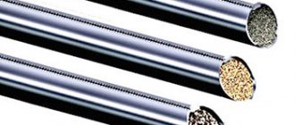
Electrodes made of the following materials are used:
- tungsten;
- graphite (carbon);
- steel coated with ionizing substances (melting).
The arc can be 3-phase. This requires a connection to the appropriate network and 2 conductive rods. A phase is connected to each of them, the third to the workpiece.
For direct and reverse polarity
DC welding can be performed in 1 of 2 ways:
- “Plus” is connected to the workpiece, i.e. it becomes the anode. This polarity is called straight.
- A minus is connected to the workpiece, so that it becomes the cathode. This is reverse polarity.
DC welding can be done in a variety of ways.
When welding with a refractory electrode, the anode spot is hotter than the cathode spot, so the first method is used to join parts of medium or large thickness. Strong heating ensures deep penetration and, as a result, high strength of the seam.
Reverse polarity connection is used to connect thin-walled workpieces. Otherwise they will burn out.
When welding with a consumable electrode, the anode spot is colder, so they do the opposite.
Arc Characteristics
The main parameters of the plasma discharge are:
- voltage;
- current strength;
- length;
- temperature.
The main parameters of a plasma discharge are voltage and current.
The interdependence of the first 2 parameters is drawn in the form of a graph.
It has 2 parts:
- Dynamic. Suitable for conditions where the working gap changes.
- Static. Displays the dependence of parameters at a constant arc length (steady state).
There are 3 areas in the graph:
- Falling. It means a sharp decrease in the potential difference with increasing amperage. At this moment, a column is formed: the conductivity of the plasma changes, and the cross-sectional area of the current becomes larger.
- Tough. Suitable for conditions where the voltage drop and current density are stable. This is explained by the fact that as the amperage increases, the cross-sectional area of the plasma increases proportionally.
- Increasing. At this stage, the interdependence of potential difference, current strength and arc resistivity corresponds to Ohm's law.
The graph allows you to estimate the discharge power.
Application area
The arc is used in the following types of welding:
- Semi-automatic. Semi-automatic welding is based on the use of refractory tungsten consumables. Filler wire is fed to the arc.
- Manual. Handmade works are the most common. This is the simplest method.
- Automatic. Automatic machines at industrial sites are more common because they are simpler in design.
The arc is used in manual, semi-automatic and automatic welding.
When welding with open plasma, a rigid arc is used; in submerged arc welding or with the supply of shielding gas, an increasing arc is used.
We recommend reading: How to weld exhaust manifolds
Tension strength
This parameter depends on 2 others:
- welding current;
- arc length.
The nature of the relationship is determined by the method of performing the work. In manual welding, as the voltage of the current source decreases, it also drops in the arc. This can be seen on the current-voltage graph. Automatic arc voltage depends only on its linear size, and is directly proportional. There is a limit above which the potential difference does not rise when the plasma discharge is stretched. It remains at this level until the arc dies out.
Tension affects the quality of the seam. If it increases, it becomes wider with a simultaneous decrease in the depth of penetration.
Burning time
Depending on the duration, there are 2 types of arc:
- permanent (stationary);
- impulse.
Depending on the duration of combustion, a constant and pulsed arc are distinguished.
The second is used in resistance welding, when current is briefly passed through 2 parts pressed against one another. As a result, the metal in the junction zone melts and a monolithic joint is formed.
Repayment terms
The arc burns when the value of its own resistance does not exceed a certain limit. This parameter increases with the length of the discharge. Accordingly, when the electrode is removed from the workpiece, the arc goes out.
This can also happen during operation if the welding parameters are selected incorrectly. The condition for arc stability is the equality Ue – I*R = Ud, where:
- Ue – potential difference at the terminals of the power source;
- I*R – voltage drop across a resistor connected to the welding machine circuit;
- Ud – the same on the arc.
If the inequality is violated, extinction becomes possible. Graphically, this looks like the location of the current-voltage characteristic of the arc above the straight line indicating the voltage drop across the resistor R.
Magnetic field dependence
From the definition of an arc it follows that it is a flow of charged particles in a plasma. This means that a magnetic field is formed around it, like around any conductor. Its lines of force are cylindrical.
A magnetic field is formed around the arc.
If the arc is in a third-party magnetic field, it will interact with its own. The discharge will become unstable.
A striking example is the so-called. magnetic blast effect that occurs when welding with direct current.
It is accompanied by the following harmful phenomena:
- A sharp shift of the pillar.
- Frequent arc breaks.
- Changes in sound, periodic claps.
As a result, the quality of the seam suffers and uncooked areas appear.
Magnetic blowing is caused by 2 reasons:
- The current in the workpiece induces a strong field. It pulls the arc column in the direction opposite to the terminal connection point.
- An array of iron or an alloy based on it, being a ferromagnetic body, causes a condensation of the field. This is explained by lower resistance to the passage of power lines compared to air. As a result, the arc shifts towards the array.
- There are powerful sources of electromagnetic radiation nearby.
The blowing effect is observed when welding with high current, since the field intensity is directly dependent on the amperage.
The blowing effect is observed when welding with high current.
Measures to combat the phenomenon:
- Reducing arc length.
- The electrode is positioned at an angle so that the end faces the direction of the magnetic blast.
- Moving the terminal closer to the arc.
- Installation of a protective screen.
- Grounding of connected parts.
When welding with alternating current, the magnetic blast is much less pronounced.
Temperature along length
The peculiarity of the structure of the welding arc lies in the temperature distribution. When welding with a refractory electrode, the cathode spot is heated to 2400-2600 °C, the anodic spot is 4-6% higher, i.e. up to 2500-2750 ˚С. The pillar is the hottest: its temperature reaches 6000-8000 °C.
Peculiarities
It has the following features compared to other electric charges:
- High current density, which reaches several thousand amperes per square centimeter, due to which very high temperatures are achieved;
- Uneven distribution of the electric field in the space between the electrodes. Near the electrodes the voltage drop is very high, when in the column it is the opposite;
- Huge temperature, which reaches the highest values in the column due to the high current density. As the length of the column increases, the temperature decreases, and when it narrows, on the contrary, it increases;
- Using welding arcs, you can obtain a wide variety of current-voltage characteristics - the dependence of the voltage drop on the current density at a constant length, that is, steady combustion. At the moment, there are three current-voltage characteristics.
The first is falling, when with an increase in strength and, accordingly, current density, the voltage drops. The second is hard, when a change in current does not affect the voltage value in any way, and the third is increasing, when as the current increases, the voltage also increases.
Thus, the welding arc can be called the best and most reliable way of fastening metal structures. The welding process has a major impact on today's industry because only the high temperature of the welding arc is capable of holding most metals together. To obtain high-quality and reliable seams, it is necessary to correctly and correctly take into account all the characteristics of the arc, monitor all values, thanks to this the procedure will be quick and most effective. It is also necessary to take into account the properties of the arc: current density, temperature and voltage.
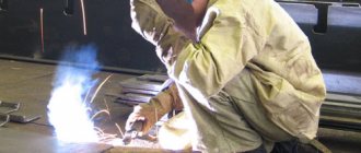
Things to know
The ultraviolet component of arc radiation is extremely dangerous to the eyes and skin, so welders use a protective suit and mask with tinted glass. Glare reflected from walls can also cause retinal burns, accompanied by severe pain.
The arc voltage in manual welding is low.
The arc voltage during manual welding is small - from 15 to 30 V. But during the process of replacing consumables, it increases to 70 V and can cause an electric shock. Special care is required from the welder.
When working with a machine, the risk of electrical injury is significantly lower.
How to adjust arc length
Not only electrical quantities, but also the quality of welding depend on this parameter. They strive to make the arc as short as possible, within 3-4 mm.
With a longer length, the following negative phenomena are observed:
- Drops of molten metal from the electrode on the way to the weld pool manage to absorb a lot of oxygen and nitrogen from the air. As a result, the seam loses strength, ductility and toughness.
- The discharge moves along the surface of the workpiece (wandering), as a result of which the heat is distributed over a relatively large area. The penetration depth decreases; drops of melt from the consumable, falling on unheated metal, do not merge with it, but bounce off.
We recommend reading: How to get a NAKS certificate
A short arc produces a dry crackling sound, reminiscent of oil sizzling in a hot frying pan.
With a long welding arc, negative phenomena are observed.
The seam she made looks neat and has the following characteristics:
- Correct form.
- Smooth convex surface.
The seam, made with a long arc, has uneven outlines, and drops of molten metal stick along it.
The consumable electrode decreases during the welding process. Therefore, it is gradually brought closer to the workpiece so that the discharge length remains constant.
Correct welding speed
When welding, it is important that the pool of molten metal immediately behind the arc is visible, but the arc itself SHOULD NOT be visible. If the melt pool and the ridge where it solidifies is visible, this indicates that the welding speed has been selected correctly. The curing boundary should be located at a distance of approximately 10 mm from the electrode.
Rice. 3
Most beginners try to weld too quickly, resulting in a thin, uneven, worm-shaped weld. This is the result of the beginner not keeping an eye on the molten metal.
Important note: When welding, it is not necessary to see the arc from the front, rear, or sides. Welding should be done at a constant speed. You will realize that it is easier to do the job this way.
Note: When welding a thin plate, the welder can increase the welding speed, but when welding a thick plate, the welder must move slowly to obtain good penetration.
About arc welding modes
The joining of parts by fusion is carried out under various conditions. A set of measures, indicators and parameters designed to ensure good quality of the weld in any situation is called the welding mode.
The parameters characterizing it are divided into 2 groups:
- basic;
- additional.
The first include:
- electrode diameter;
- current strength;
- arc voltage.
The joining of parts by fusion is carried out under various conditions.
Extra options:
- position of the seam in space;
- speed of work;
- composition and thickness of the metal.
The current strength is determined by the properties of the welding machine and is indicated in the instructions for it. The amount of heat generated, and therefore the depth of penetration, depends on it. Thick-walled elements of large metal structures exposed to heavy loads are connected with increased current. On the contrary, it can burn through a thin part, so the amperage is reduced.
The diameter of the electrode must correspond to the current strength.
Otherwise, the following negative points arise:
- Reduced diameter. The coating on the rod is damaged and the arc becomes unstable.
- Oversized diameter. The current density decreases, the length of the arc and its position become unstable, the seam becomes uneven and fragile.
Parameters of manual welding modes are given in the table:
| Thickness of welded parts, mm | 0,5 | 1-2 | 3 | 4-5 | 6-8 | 9-12 | 13-15 | 16 |
| Electrode diameter, mm | 1 | 1,5-2 | 3 | 3-4 | 4 | 4-5 | 5 | 6-8 |
| Current strength, A | 10-20 | 30-45 | 65-100 | 100-160 | 120-200 | 150-200 | 160-250 | 200-350 |
Regardless of the thickness of the workpieces, seams on vertical surfaces and ceilings are made with an electrode with a diameter of 4 mm.
Powerful connections are made in several approaches:
- Boil the root of the seam using a rod with a diameter of 3-4 mm.
- Apply the required amount of surfacing using thicker products.
Powerful connections are made in several approaches.
As the speed of the process increases, the width of the seam decreases, and vice versa. This parameter should be kept within reasonable limits. If the speed is too high, the metal does not have time to completely melt, and uncooked areas form in the joint. When welding slowly, the steel spreads, which also negatively affects the quality of the seam.
The width of the connection and the depth of penetration depend on the trajectory of the electrode. It is moved in a straight line, zigzag, herringbone, etc.