general information
Electric arc welding is a method of joining metals that is based on the use of an electric arc. The arc heats and melts the metal, allowing a weld to be formed. Can reach temperatures over 6000 degrees. This is sufficient to melt most existing types of metals.
Electric arc technology is widely used in welding and cutting metals. It can be manual, semi-automatic and automatic.
Gas cutting
Oxygen cutting is based on the ability of certain metals to burn in a stream of oxygen, releasing more heat.
Using the gas-oxygen method, it is possible to cut only those metals whose ignition temperature (Tv) is lower than the melting temperature (Tm), and the melting temperature of the resulting oxides (Current) is lower than the melting temperature of the metal. Oxides must have good fluidity and can be easily removed by blowing with air or an oxygen stream. To concentrate heat, the thermal conductivity of the metal must be low. This method can cut carbon steel containing up to 0.7% C and low-alloy structural steels. When cutting high-carbon steels, they require preheating to 650–700 °C.
Cast iron, high-alloy chromium and chromium-nickel steels, and non-ferrous alloys cannot be gas-cut, since the melting point of the resulting oxides is higher than the melting point of the alloys.
Oxygen gas cutting is carried out using conventional gas welding equipment, only instead of a welding torch, a cutter is attached that supplies a gas mixture to heat the metal and oxygen to burn it. The cutter has replaceable mouthpieces - heating (external) and cutting (internal).
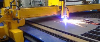
Rice. 42. Gas cutting : a – process diagram: 1 – jet of cutting oxygen; 2 – heating flame; 3 – metal product; 4 – cutting zone; 5 – blown oxides; b – automatic cutting of metal with gas
A diagram of the gas cutting process is shown in Fig. 42. A mixture of oxygen and combustible gas is directed into the annular channel of the cutting torch mouthpiece. When leaving the mouthpiece, the gas mixture is ignited, forming a flame 2, which is directed to the metal being cut 3. After heating the metal to the required temperature, the supply of flammable gas stops and the flow of oxygen increases, the stream 1 of which, when leaving the mouthpiece, in contact with the heated metal, activates combustion. During the combustion of the metal, oxides 5 are formed, which are carried away by the jet of cutting oxygen and then blown out of the cut cavity 4. Thus, gas cutting consists of three processes: heating the metal, burning the metal in an oxygen environment, and blowing out the oxides.
Electric arc welding technology
Electric arc welding technology is simple. The welding machine is connected to the network. One cable is connected to the part, and the second to the electrical holder with the electrode. The end of the electrode is tapped on the surface of the metal, exciting an arc. An arc is formed between the electrode and the metal being welded. The arc instantly begins to give off heat, melting the edges of the metal and the electrode itself (if it is consumable). As a result, a weld pool is formed.
It mixes the molten electrode and the base metal. They fill the joint between two parts, and after cooling, a strong, permanent connection is formed. In this case, so-called slag can form on the surface of the weld. To perform welding, you can use consumable and non-consumable electrodes or wire. The choice depends on the arc welding technology you choose. For example, in manual arc welding, consumable electrodes are most often used. And for semi-automatic welding - consumable or non-consumable wire.
If you do not know how to maintain a stable arc, you can use special electrodes or welding wire. They must contain sodium, potassium or calcium. These elements stabilize the arc due to their ionizing properties.
Shielding gas can be used to protect the welding area from oxidation. For example, argon or carbon dioxide. Such gases are supplied directly to the weld pool, protecting it from oxygen from the atmosphere.
Electric arc welding can be carried out with both direct and alternating current. We recommend using direct current, since the metal will splatter less and the seam will be of much better quality. If you are a beginner, then DC operation is a must.
Read also
Chapter 3 TOOLS AND EQUIPMENT FOR GLASS CUTTING AND STORAGE
Chapter 3 TOOLS AND EQUIPMENT FOR GLASS CUTTING AND STORAGE 1. Equipment and tools for glass cutting To perform glass work, including cutting, teams must be provided with the following equipment and tools (Fig. 164): cutting tables
1. Glass cutting equipment and tools
1. Equipment and tools for cutting glass To perform glass work, including cutting, teams must be provided with the following equipment and tools (Fig. 164): tables for cutting glass, glass cutters, rulers, squares, meters, tape measures
Oxygen cutting technology
Oxygen cutting technology The essence of oxygen cutting is the combustion of the metal being cut under the influence of a stream of oxygen and the removal of slag from the cut, the formation of which inevitably accompanies this process (Fig. 21). Carbon, as well as low-alloy
Welding materials and equipment for arc welding
Welding materials and equipment for arc welding Welding wire To fill the gap between the parts being welded, a filler material is used, which has the form of a rod or wire and is introduced into the welding arc zone. If a manual arc is used
Arc welding technique
Arc welding technique Welding work involves a certain preparation of parts, which includes several operations:? editing, which is carried out on machines or manually. For example, for straightening sheet and strip metal, various
Electric arc cutting of metals
Metal cutting using arc welding is one of the oldest cutting methods. There is manual arc cutting using a consumable or non-consumable electrode and air and oxygen-arc cutting. Let's take a closer look at each of the methods.
Non-consumable electrode cutting
Let's start with a little used, but still used method. Cutting with non-consumable electrode. A graphite or carbon rod is used as an electrode; cutting is performed using any type of current, but with straight polarity. The current strength should not exceed 800A. To cut metal, it must first be heated with an arc and then smelted.
Why is this method little used? The point is that it is only applicable in special cases. For example, when cutting scrap or dismantling old metal structures. In short, for working with complex large-sized projects. There is also no need to talk about the beauty of the cut. The work turns out uneven and sloppy. But this method can cut any metals: from cast iron to non-ferrous metals.
Consumable electrode cutting
But cutting with a consumable electrode is perhaps the most common method of electric arc cutting. The cut is much neater and smoother than when using the previous method. To perform cutting, set a higher amperage (30 percent more than when welding). You can focus on the thickness of the electrode. For a rod 1 millimeter thick, set the current to approximately 50A. For a 2 mm rod - 100A. And so on. The metal itself must be heated with deep penetration. This heating method is also called the “support method”. Can cut most metals.
To perform a simple cut at home, you can use any consumable electrodes. But to achieve better results, use special electrodes for cutting metal. Usually special electrodes have a special coating. Thanks to it, the welding process is faster and easier.
But despite the improved cut quality, it is still far from ideal. If we compare this method of cutting metals with more technologically advanced ones, it will lose in everything. Starting from the quality of the cut, ending with its aesthetic characteristics. At the same time, the cutting process itself is very slow.
Air and oxygen arc cutting
Air-arc and oxygen-arc cutting of metal using electric arc welding have no differences, except for one thing. In air cutting, the metal is first melted by the heat of the arc, and then it is blown out using compressed air. When using oxygen cutting, the technology is the same, but instead of air, an oxygen flow is used.
This cutting method is used when working with stainless steel sheets. In this case, the thickness of the sheet should not exceed 20 millimeters. Also, such cutting methods are used to remove defective parts from a part.
To perform such cutting, you need to set the welding machine to constant current and select graphite electrodes. Tubular electrodes can also be used. When using tubular electrodes, oxygen is supplied through a through hole in the welding rod. The method is effective, but labor-intensive. It is much easier to apply compressed air or a stream of oxygen directly to the incision site.
Physical principles of cutting
The oxygen-arc cutting method is a physical process of complete or partial separation of metal, which is based on the action of an oxygen jet and an electric arc. The technology is used to work with products up to 120 mm thick, made of carbon steel grades. Unlike arc cutting, the operation uses an oxygen jet, which is supplied to the work area under high pressure and oxidizes the steel alloy, removing combustion products. This technique allows you to expand cutting capabilities by increasing the amount of thermal energy, which speeds up the process and increases cutting efficiency. In hardware, steel tubes with a length of 340 mm to 400 mm and a diameter of 8 mm act as electrodes.
The technological process of metal separation is based on the simultaneous influence of two factors. The metal is heated by an electric arc, and then burned by a stream of oxygen supplied parallel to the electrode. In practice, both consumable tubular and graphite carbon electrodes are used. As the cutting moves, the cutting oxygen jet follows the movement of the electrode, forming a cut.
The essence and application of plasma-arc cutting
The essence and application of air-arc cutting.
The essence and application of arc cutting.
Topic 3.3.2 Arc, air-arc and plasma-arc cutting
Questions:
1. Electric arc cutting . The heat of the electric arc melts the metal, which flows out of the cutting cavity - this is the essence of electric arc cutting. Arc 2
burns between the steel or carbon electrode
1
and the metal being cut
3
(Fig. 87).
Cutting is carried out both on direct and alternating current, on the equipment that is used for welding. Current strength 300...350 A.
Electrodes with a thick layer of chalk coating work well.
The method under consideration is used for rough cutting of metal, mainly on construction sites. The cutting quality is low and productivity is also low.
Arc cutting is usually performed manually using carbon (graphite) or metal electrodes. Cutting with carbon electrodes is carried out on direct current, with metal electrodes - on direct and alternating current. Rice. 87 Electric arc cutting
Cutting is carried out using steel electrodes with a high-quality coating, but more refractory than for welding. This coating ensures the formation of a small visor during cutting, covering the arc area. The visor protects the electrode from a short circuit to the metal being cut, and also promotes more concentrated heating of the metal and allows for more productive cutting. A mixture containing 70% manganese ore and 30% liquid glass is used as a coating. Coated electrodes TsM-7 and TsM-7s are also successfully used.
Arc cutting with a rotating steel disk is carried out as follows. An electric current is supplied to the steel sheet and the metal being cut. When the rotating disk comes into contact with the metal being cut, an arc occurs, which melts the metal and throws it out of the cut site. In production plants, steel disks with a diameter of up to 500 mm and a thickness of 4...6 mm are used. The disk rotates at a speed of about 40 m/s. To cool the disk, compressed air with a pressure of up to 0.5 MPa is used. The arc power source is any step-down transformer with a power of up to 30 kW with an open circuit voltage of 10...30 V. The cutting performance is proportional to the power of the power source. The thermally affected zone at the edges of the cut metal is up to 1 mm. Wear of the working edge of the steel disk electrode does not exceed 2% of the mass of the removed metal. When using electrodes reinforced with inserts made of a resistant alloy, wear is reduced by up to 20 times.
In terms of labor productivity and cut cleanliness, arc cutting is significantly inferior to gas cutting and is therefore of secondary importance. It is used primarily in cases where for some reason it is not possible to use gas cutting. Arc cutting is used to remove sprues and profits of cast iron castings; when dismantling and cutting old metal structures into dimensional scrap, especially if these structures have seams or parts of chromium-nickel austenitic steels, which usually require special gas cutting methods; during installation work to remove mounting fixtures.
Air arc cutting. This method is a type of electric arc cutting. The metal melted by the electric arc is continuously removed by a stream of compressed air. In addition to cutting, this method successfully performs surface treatment of metal: cutting grooves, cutting cracks, removing defective areas at the root of the weld, cutting rivets, etc. Any electrodes can be used. As a rule, carbon electrodes are used. Compressed air enters the cutter from the air line at a pressure of 3...6 ati. The cutting speed of carbon and low-alloy steels up to 30 mm thick is 0.4…0.5 m/min.
Electric arc cutting and its variations can be used when working under water. In Fig. 88 shows a diagram of the air-arc cutting process.
Fig.88 Scheme of the air-arc cutting process:
1 – cutter; 2 – air stream; 3 – groove; 4 – electrode (carbon)
Air-arc cutting of metals is performed with direct current of reverse polarity, since with an arc of direct polarity the metal is heated over a relatively wide area, as a result of which removal of the molten metal is difficult. It is also possible to use alternating current. For air-arc cutting, special cutters are used, which are divided into cutters with a sequential air jet arrangement and cutters with a ring air jet arrangement.
In cutters with a sequential arrangement of the air jet relative to the electrode, compressed air flows around the electrode on only one side.
For air-arc cutting, carbon or graphite electrodes are used. Graphite electrodes are more durable than carbon electrodes. Electrodes come in round and plate shapes. The magnitude of the current during air-arc cutting is determined by the following relationship I = K · d, where I is the current, A; d – electrode diameter, mm; K is a coefficient depending on the thermophysical properties of the electrode material, equal to 46...48 A/mm for carbon electrodes and 60...62 A/mm for graphite ones.
Power sources for air-arc cutting are standard DC welding converters or welding transformers.
The cutter is powered with compressed air from a workshop network having a pressure of 0.4...0.6 MPa, as well as from mobile compressors. The use of compressed air during air-arc cutting with a pressure above 0.6 MPa is impractical, since a strong air jet sharply reduces the stability of the arc.
Air arc cutting is divided into surface gouging and separation cutting. Surface gouging is used for cutting defective areas in metal and welds, as well as for cutting the root of a weld and chamfering. The chamfer can be removed simultaneously on both edges of the sheet. The width of the groove formed during surface gouging is 2...3 mm greater than the diameter of the electrode. Air arc separation cutting and gouging is used when processing stainless steel and non-ferrous metals. It has a number of advantages over other methods of fire processing of metals, since it is simpler, cheaper and more productive.
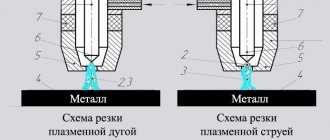
3.Plasma arc cutting (Fig. 89, a) is based on the ability of a compressed arc to penetrate deeply into the metal, melting it along the cut line with an arc discharge. Under the influence of the high temperature of the compressed arc, gas 2, passing through the arc discharge, strongly ionizes, a plasma jet is formed, which removes the molten metal from the cut site.
Arc 1 is excited between the metal being cut 4 and a non-consumable tungsten electrode 5 located inside the cutter head 6. Arc gas-discharge plasma 3 is called low-temperature (its temperature is 5000...20000 ° C).
Rice. 89 Scheme of the plasma arc cutting process:
a – plasma arc, b – plasma jet
The plasma-forming gases used in plasma-arc cutting must ensure the production of plasma and the necessary protection of the tungsten electrode from oxidation. Argon, nitrogen and mixtures of argon with nitrogen, hydrogen and air are used as such gases. Lanthanated tungsten VL-15 is used as electrodes. The tungsten electrode is placed coaxially with the plasmatron nozzle. The plasma jet has a high exhaust velocity and has the shape of an elongated cone, the cross-section of which at the exit corresponds to the cross-section of the nozzle.
Plasma arc cutting is used to cut metals that are impossible or difficult to cut by other methods, for example, when cutting corrosion-resistant alloy steels, aluminum, magnesium, titanium, cast iron and copper.
When cutting with a plasma jet, the metal being cut is not included in the electrical circuit of the arc. The arc burns between the end of the tungsten electrode and the inner wall of the water-cooled tip of the plasma torch. The essence of plasma arc cutting is to melt the metal with a plasma jet and blow out the molten metal from the cutting zone.
In Fig. 89, b schematically shows the process of cutting with a plasma jet. Power is supplied from a direct current source 3. The minus is supplied to the tungsten electrode 4, and the plus to the copper nozzle 2, which is cooled by water. The arc 6 burns between the electrode and the nozzle and is blown out by a gas mixture from the internal cavity of the mouthpiece 5 to form a plasma jet 1, which melts the metal 7 being cut. Argon and a mixture of argon and nitrogen are mainly used as plasma-forming gas.
A plasma jet is used when cutting thin metal.
The cutting speed of a plasma jet depends on the properties of the metal being cut and on the parameters and cutting mode (current strength, voltage, gas flow). Plasma jet cutting is carried out both manually and mechanized.
For plasma arc cutting, special equipment is used that is powered by electrical energy. The main element in plasma cutting is the cutting plasma torch. The hand-held plasma torch has a device for controlling the cutting operating cycle - supply and shut-off of gases, ignition of the pilot arc.
The essence and application of air-arc cutting.
The essence and application of arc cutting.
Topic 3.3.2 Arc, air-arc and plasma-arc cutting
Questions:
1. Electric arc cutting . The heat of the electric arc melts the metal, which flows out of the cutting cavity - this is the essence of electric arc cutting. Arc 2
burns between the steel or carbon electrode
1
and the metal being cut
3
(Fig. 87).
Cutting is carried out both on direct and alternating current, on the equipment that is used for welding. Current strength 300...350 A.
Electrodes with a thick layer of chalk coating work well.
The method under consideration is used for rough cutting of metal, mainly on construction sites. The cutting quality is low and productivity is also low.
Arc cutting is usually performed manually using carbon (graphite) or metal electrodes. Cutting with carbon electrodes is carried out on direct current, with metal electrodes - on direct and alternating current. Rice. 87 Electric arc cutting
Cutting is carried out using steel electrodes with a high-quality coating, but more refractory than for welding. This coating ensures the formation of a small visor during cutting, covering the arc area. The visor protects the electrode from a short circuit to the metal being cut, and also promotes more concentrated heating of the metal and allows for more productive cutting. A mixture containing 70% manganese ore and 30% liquid glass is used as a coating. Coated electrodes TsM-7 and TsM-7s are also successfully used.
Arc cutting with a rotating steel disk is carried out as follows. An electric current is supplied to the steel sheet and the metal being cut. When the rotating disk comes into contact with the metal being cut, an arc occurs, which melts the metal and throws it out of the cut site. In production plants, steel disks with a diameter of up to 500 mm and a thickness of 4...6 mm are used. The disk rotates at a speed of about 40 m/s. To cool the disk, compressed air with a pressure of up to 0.5 MPa is used. The arc power source is any step-down transformer with a power of up to 30 kW with an open circuit voltage of 10...30 V. The cutting performance is proportional to the power of the power source. The thermally affected zone at the edges of the cut metal is up to 1 mm. Wear of the working edge of the steel disk electrode does not exceed 2% of the mass of the removed metal. When using electrodes reinforced with inserts made of a resistant alloy, wear is reduced by up to 20 times.
In terms of labor productivity and cut cleanliness, arc cutting is significantly inferior to gas cutting and is therefore of secondary importance. It is used primarily in cases where for some reason it is not possible to use gas cutting. Arc cutting is used to remove sprues and profits of cast iron castings; when dismantling and cutting old metal structures into dimensional scrap, especially if these structures have seams or parts of chromium-nickel austenitic steels, which usually require special gas cutting methods; during installation work to remove mounting fixtures.
Air arc cutting. This method is a type of electric arc cutting. The metal melted by the electric arc is continuously removed by a stream of compressed air. In addition to cutting, this method successfully performs surface treatment of metal: cutting grooves, cutting cracks, removing defective areas at the root of the weld, cutting rivets, etc. Any electrodes can be used. As a rule, carbon electrodes are used. Compressed air enters the cutter from the air line at a pressure of 3...6 ati. The cutting speed of carbon and low-alloy steels up to 30 mm thick is 0.4…0.5 m/min.
Electric arc cutting and its variations can be used when working under water. In Fig. 88 shows a diagram of the air-arc cutting process.
Fig.88 Scheme of the air-arc cutting process:
1 – cutter; 2 – air stream; 3 – groove; 4 – electrode (carbon)
Air-arc cutting of metals is performed with direct current of reverse polarity, since with an arc of direct polarity the metal is heated over a relatively wide area, as a result of which removal of the molten metal is difficult. It is also possible to use alternating current. For air-arc cutting, special cutters are used, which are divided into cutters with a sequential air jet arrangement and cutters with a ring air jet arrangement.
In cutters with a sequential arrangement of the air jet relative to the electrode, compressed air flows around the electrode on only one side.
For air-arc cutting, carbon or graphite electrodes are used. Graphite electrodes are more durable than carbon electrodes. Electrodes come in round and plate shapes. The magnitude of the current during air-arc cutting is determined by the following relationship I = K · d, where I is the current, A; d – electrode diameter, mm; K is a coefficient depending on the thermophysical properties of the electrode material, equal to 46...48 A/mm for carbon electrodes and 60...62 A/mm for graphite ones.
Power sources for air-arc cutting are standard DC welding converters or welding transformers.
The cutter is powered with compressed air from a workshop network having a pressure of 0.4...0.6 MPa, as well as from mobile compressors. The use of compressed air during air-arc cutting with a pressure above 0.6 MPa is impractical, since a strong air jet sharply reduces the stability of the arc.
Air arc cutting is divided into surface gouging and separation cutting. Surface gouging is used for cutting defective areas in metal and welds, as well as for cutting the root of a weld and chamfering. The chamfer can be removed simultaneously on both edges of the sheet. The width of the groove formed during surface gouging is 2...3 mm greater than the diameter of the electrode. Air arc separation cutting and gouging is used when processing stainless steel and non-ferrous metals. It has a number of advantages over other methods of fire processing of metals, since it is simpler, cheaper and more productive.
3.Plasma arc cutting (Fig. 89, a) is based on the ability of a compressed arc to penetrate deeply into the metal, melting it along the cut line with an arc discharge. Under the influence of the high temperature of the compressed arc, gas 2, passing through the arc discharge, strongly ionizes, a plasma jet is formed, which removes the molten metal from the cut site.
Arc 1 is excited between the metal being cut 4 and a non-consumable tungsten electrode 5 located inside the cutter head 6. Arc gas-discharge plasma 3 is called low-temperature (its temperature is 5000...20000 ° C).
Rice. 89 Scheme of the plasma arc cutting process:
a – plasma arc, b – plasma jet
The plasma-forming gases used in plasma-arc cutting must ensure the production of plasma and the necessary protection of the tungsten electrode from oxidation. Argon, nitrogen and mixtures of argon with nitrogen, hydrogen and air are used as such gases. Lanthanated tungsten VL-15 is used as electrodes. The tungsten electrode is placed coaxially with the plasmatron nozzle. The plasma jet has a high exhaust velocity and has the shape of an elongated cone, the cross-section of which at the exit corresponds to the cross-section of the nozzle.
Plasma arc cutting is used to cut metals that are impossible or difficult to cut by other methods, for example, when cutting corrosion-resistant alloy steels, aluminum, magnesium, titanium, cast iron and copper.
When cutting with a plasma jet, the metal being cut is not included in the electrical circuit of the arc. The arc burns between the end of the tungsten electrode and the inner wall of the water-cooled tip of the plasma torch. The essence of plasma arc cutting is to melt the metal with a plasma jet and blow out the molten metal from the cutting zone.
In Fig. 89, b schematically shows the process of cutting with a plasma jet. Power is supplied from a direct current source 3. The minus is supplied to the tungsten electrode 4, and the plus to the copper nozzle 2, which is cooled by water. The arc 6 burns between the electrode and the nozzle and is blown out by a gas mixture from the internal cavity of the mouthpiece 5 to form a plasma jet 1, which melts the metal 7 being cut. Argon and a mixture of argon and nitrogen are mainly used as plasma-forming gas.
A plasma jet is used when cutting thin metal.
The cutting speed of a plasma jet depends on the properties of the metal being cut and on the parameters and cutting mode (current strength, voltage, gas flow). Plasma jet cutting is carried out both manually and mechanized.
For plasma arc cutting, special equipment is used that is powered by electrical energy. The main element in plasma cutting is the cutting plasma torch. The hand-held plasma torch has a device for controlling the cutting operating cycle - supply and shut-off of gases, ignition of the pilot arc.