The welding arc, discovered more than 100 years ago, has found wide application in industry. It provides a strong connection of metal workpieces, transforming them into a monolithic structure. To ensure a high-quality seam, you must choose the right power source.
A welding arc is a long-lasting electrical discharge in a plasma.
What is a welding arc and why is it called that?
By definition, a welding arc is an electrical discharge that can burn stably due to the action of an electric field. A welding arc occurs only when an ionized mixture of gases and metal vapors occurs. It is used as a metal processing tool, being a concentrated source of thermal energy. The temperature on the arc can reach 20,000 degrees Celsius, which is used not only for welding, but also for cutting thick metal.
The name arc itself appeared in 1802 during experiments described by V.V. Petrov. The experiment was carried out with columnar discharges that bent into an “Arc” under the influence of warm air heated by them.
Classification of welding arc - main types
There are several different classifications of the welding arc:
- Depending on the connection to the welding machine.
- According to the electrodes used in the process.
- Depending on the current.
- By degree of compression.
- Depending on the protection.
- Depending on the length.
From connection to the welding machine
There is already an internal classification here: direct action; indirect and combined.
- Direct action - the arc burns between the part and one electrode;
- Indirect - the discharge burns between several electrodes, no current is supplied to the products (for example, atomic-hydrogen surfacing and welding)
- The combined method includes a symbiosis of direct and indirect methods. The arc burns both between the electrodes and between the products (performed on three-phase current)
According to the electrodes used in the process
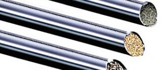
When welding, the following types of electrodes can be used, from which the arc and its properties will differ:
- consumable electrodes - piece electrodes with coating and a metal rod inside, flux-cored wire and solid wire;
- non-consumable carbon or graphite electrodes;
- non-consumable electrodes made of tungsten and various refractory additives of lanthanum, yttrium, thorium and others.
From current
Depending on the current, there is the following classification:
- DC arc;
- Alternating current;
- Pulse.
In turn, the DC arc is divided into:
- straight polarity;
- reverse polarity.
By degree of compression
The arc can be:
- free-burning - the arc discharge burns in a protective atmosphere without measures to increase pressure and compression.
- Compressed - the arc discharge is compressed by air or inert gas using special nozzles and plasmatrons or using an electromagnetic field.
Depending on the protection
Here are the following three classifications:
- open - protection is carried out by the gaseous environment formed from the evaporation of the electrode coating;
- open in an inert gas environment - protection is carried out by supplying inert gas;
- closed under a layer of flux - protection is carried out due to the melting of the flux, under which it burns.
Depending on the length
Classification depending on the distance between the electrode and the product:
- Short - 1.5-2.0 mm long.
- Normal 2.0 - 3.0 (maximum 3.5 mm).
- Long - more than 3.5 mm.
Useful article - How to weld with electrodes for beginners.
How an electric arc is formed
A welding arc is nothing other than an electrical discharge. It appears when the circuit is closed. At the moment of contact of the electrode with the structural element being welded, thermal energy begins to be produced in excess. The metal melts at the point of contact. Due to the phenomenon of attraction of the melt to the tip of the consumable element, a thin neck is formed. Under the influence of a powerful electric field, it is practically instantly sprayed. This causes the ionization of gas molecules. As a result of this process, a protective cloud is formed, ensuring the free movement of electrons.
The direction of the flow is determined by the type of current. An electric arc can be ignited using an electric current of both constant and variable magnitude, as well as any polarity - both direct and reverse. The frequency of arc ignition and extinction is a characteristic derived from the set of current parameters selected by the worker.
Nature of occurrence
An electric welding arc can only burn in an ionized gas environment. An ionized gas environment is a gas or mixture of gases containing negatively charged electrons and positively charged ions. Under normal conditions, any gas, including air, does not have electrically charged particles.
The process of gas ionization occurs when the arc is ignited when the electrode touches the metal. At this moment, a short circuit occurs and the metal partially melts.
Due to the high temperature during a short circuit, electrons of negatively charged particles are released from the surface of the cathode (in this case, the welding electrode) and positively charged ions from the product.
The process of formation of electrons from the cathode under the influence of temperature is called thermionic emission.
After ionization due to emission has occurred, the welding arc begins to burn steadily. The ionization process occurs during the entire arc burning period.
Structure and zone of the anode spot
There are 3 sections in the structure of the arc:
- Cathode spot. It is the site of acceleration and emission of electrons and has a negative charge. The size of this zone is approximately 1 micron (0.001 mm). 38% of the heat is released here, the voltage drop is 12-17 V.
- Arc pillar. Has a neutral charge because positive and negative particles are present in equal quantities. The average length is 5-10 mm. In this area, 20% of the heat is released and 2-12 V is lost.
- Anode spot. Bombarded with electrons, which gives it a concave shape (crater). The length of this zone is 10 µm. 42% of heat is released, 2-11 V is lost.
Structure and properties of the electric welding arc.
The given data are typical for welding with a refractory electrode.
Conditions of education
The main conditions for the formation of a welding arc are the following stages:
- Primary short circuit between electrode and product.
- The appearance of molten metal in the area between the electrode and the product.
- After the electrode is withdrawn, a pull out of the metal is formed - a “neck” is formed.
- The “neck” breaks with the formation of ionized gas.
- The appearance of a stable burning arc.
To maintain and stable combustion of the arc column, continuous ionization of the gas is necessary. For this purpose, either protective gases that have a high degree of ionization such as argon and helium are used.
If welding is performed using electrodes, then the composition of the coating includes additives from alkaline earth and alkali metals such as potassium, sodium and others. Due to this, there is an increase in ionization during combustion and melting of the electrode coating.
Arc protection
Examples of protective suits against electric arc
If welding machines use an arc, then many other machines and in addition a person should avoid it. The risk of arcing on equipment depends on several factors:
- frequency of use of the equipment by the employee;
- experience and knowledge of workers dealing with hardware
- equipment wear level;
If a person is not wearing the necessary personal protective suit and falls into the area of effect of the electric arc, the chances of survival decrease quite sharply. The risk of severe burns is extremely high.
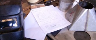
Table
Table: degree of exposure to electric arc
What are the possibilities for protection from email? Dougie?
- comply with all necessary safety rules and regulations;
- in case of prolonged use of protective material, frequent washing, the suit should not deteriorate; (it all depends on the model);
- the fabric must have a maximum of 2 seconds of residual combustion;
- you must wear special shoes that have an antistatic effect and also have a suit for protection against electric arcs .
Power supplies (devices)
To create an arc, alternating, direct and pulsed current devices are used.
Alternating current is created by single-phase and three-phase transformers. Single-phase requires 220 volts, three-phase 380 volts (used in industry).
For direct current, welding inverters, rectifiers and autonomous units are used.
The most modern are inverter power supplies. Due to transistor control, inverters optimize the welding process by adjusting the current-voltage characteristic. You can find out what types of welding machines are used for manual welding from our article by clicking on the link.
Multi-station rectifiers are used in production and most often have a rigid current-voltage characteristic.
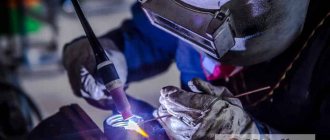
What does a welding arc look like?
The welding arc looks like a vertically oriented, brightly glowing column of heated gas.
This is due to the fact that during the burning of an electric discharge, electromagnetic waves of the visible and invisible spectrum are emitted such as:
- infrared;
- ultraviolet;
- visible spectrum radiation.
During the process, one can clearly see the electron spots of the anode and cathode regions, which glow brightly.
AC Welding
Everything described above concerned the procedure for welding with direct current. However, alternating current can also be used for these purposes. As for the negative aspects, there is a noticeable deterioration in stability, as well as frequent jumps in the combustion temperature of the welding arc. One of the advantages is that you can use simpler, and therefore cheaper equipment. In addition, in the presence of a variable component, such an effect as magnetic blast practically disappears. The last difference is that there is no need to select polarity, since with alternating current the change occurs automatically with a frequency of about 50 times per second.
It can be added that when using manual equipment, in addition to the high temperature of the welding arc with the manual arc method, infrared and ultraviolet waves will be emitted. In this case, they are emitted by a discharge. This requires maximum protection for the worker.
Welding arc characteristics
The main characteristics of the welding arc are:
- length;
- voltage;
- temperature;
- type and polarity of current;
- volt-ampere characteristics
Current and voltage
The arc voltage fluctuates in the range of 12-65 Volts. The voltage is calculated from the sum of the voltages of the cathode spot, anode spot, and arc column.
Ud = Uк + Uct + Ua ≈ 8+2x1.5+6 ≈ 17 V - for manual welding with a short arc.
Important! The arc voltage will increase as the arc length increases. The arc column voltage increases by 2 Volts with increasing distance by 1 mm.
Voltage and current determine the power of the welding arc. The greater the voltage and current, the greater the power, and therefore the more heat introduced into the metal.
What is the temperature and how is it distributed along the length of the arc?
The temperature along the arc is distributed unevenly; at the cathode and anode spots the temperature is significantly lower than the temperature at the column.
For a free-burning arc, in the figure below you can see the temperature distribution along its length.
The temperature distribution for welding in an argon environment, as well as for plasma welding (distribution in a compressed arc) is shown in the diagram below.
And we described in detail how to cook with argon in our article, follow the link.
Ignition and burning time
In terms of time, the welding arc is limited only by the desire of the welder himself. The process of igniting the arc takes from a few milliseconds to several seconds, depending on the equipment used, the skill of the welder and the quality of preparation. Ionization of the arc gap occurs in a few milliseconds.
Interruption (quenching) conditions
To interrupt the process, the welder increases the length of the arc until it breaks. This occurs due to an increase in resistance.
A break during execution may be due to: low qualifications of the welder, equipment malfunction, as well as voltage drops in the supply network.
Impact of magnetic field
An arc is a flexible electrical discharge that changes its direction. It is influenced by magnetic fields causing it to deflect. This is similar to the deflection of the flame of a match when the wind blows on it. This effect is called magnetic blowing.
This effect negatively affects the welding process as the direction of the column changes and the combustion becomes unstable.
The main causes of magnetic blowing are:
- The presence of an external source of magnetic field (for example, the magnetic grip of a crane)
- Asymmetrical current supply to the part, which induces a strong magnetic field.
- A large amount of ferromagnetic material near the welding area.
To eliminate the effect of magnetic blast, you should adhere to the following recommendations:
- Connect the ground as close as possible to the welding zone.
- Placement of compensating ferromagnetic materials near the welding zone.
- use of inverter power sources for DC welding.
- When you can use alternating current, use a transformer.
- Ground the part to be welded.
- Cover the welding area with metal shielding surfaces to protect against magnetic fields.
- Perform the process with a short arc (length up to 1.5 mm)
If the methods indicated above did not help, you need to use a more radical, but also more labor-intensive method.
It is necessary to wind an inductor (thick copper cable with a cross-section of 120 - 240 mm2) from 6 to 10 turns onto the part.
Connect to a DC source (to a rectifier) and apply a current of 250-350 amperes for 3-5 minutes. After this procedure, you need to check whether the magnetization effect of the product has been eliminated. If the product is magnetic, then you need to swap the inductor terminals, connect plus to minus, and minus to plus, and repeat the process again.
If you want to learn how to cook using inverter welding yourself, follow the link to our article.
Basic properties of arc discharge
During operation, in order to initiate an arc discharge, the workpiece is briefly touched by the electrode, that is, a short circuit is created, followed by breaking of the metal contact and establishing the required air gap. In this way, the optimal length of the welding arc is selected.
With a very short discharge, the electrode may stick to the workpiece, melting occurs too intensely, which can lead to the formation of sagging. A long arc is characterized by instability of combustion and insufficiently high temperature in the welding zone.
Instability and visible bending of the welding arc shape can often be observed during the operation of industrial welding units with fairly massive parts. This phenomenon is called magnetic blowing.
Its essence lies in the fact that the welding arc current creates a certain magnetic field, which interacts with the magnetic field created by the current flowing through the massive workpiece.
That is, the deflection of the arc is caused by magnetic forces. The process is called blowing because the arc is deflected, as if under the influence of wind.
There are no radical ways to combat this phenomenon. To reduce the influence of magnetic blast, welding with a shortened arc is used, and the electrode is also placed at a certain angle.
Current-voltage characteristic (CVC)
The current-voltage characteristic (or VAC for short) is a graph of voltage versus current. There are current-voltage characteristics for the welding arc, as well as external current-voltage characteristics of power sources.
For a welding arc, a static current-voltage characteristic is plotted at its constant length.
It is divided into three sections:
- low currents;
- average currents;
- high currents.
In areas of low currents, it has a falling characteristic, and the arc has low stability (section I in the diagram).
In the medium current section the characteristic becomes rigid. At a constant (minor changes, of course, there are still minor changes) voltage, the current increases (section II in the diagram).
In areas of high currents, there is a strong increase in ionization due to which the current-voltage characteristic increases (it is used in automatic welding methods in shielding gases and under a layer of flux).
Below are the external current-voltage characteristics for welding machines.
The arc current-voltage characteristic must be taken into account when choosing welding equipment.
For manual welding with consumable and non-consumable electrodes, you need to use devices that have a falling or steeply falling current-voltage characteristic.
This will allow you to adjust the current strength at different arc lengths, which will change during the welding process. Since the welder is not a robot and one way or another he will shorten the arc gap in some places and increase it in others.
Below is a table for selecting a power source with the required I-V characteristics depending on the required I-V characteristics of the arc.
| Arc current-voltage characteristic | External current-voltage characteristics of the device (power supply) | |||
| Steeply falling | Flat falling | Tough | Increasing | |
| Serving | + | + | — | — |
| Tough | + | + | — | — |
| Increasing | — | — | + | + |
“+” — Corresponds; "-" - does not match
Things to know
The ultraviolet component of arc radiation is extremely dangerous to the eyes and skin, so welders use a protective suit and mask with tinted glass. Glare reflected from walls can also cause retinal burns, accompanied by severe pain.
The arc voltage in manual welding is low.
The arc voltage during manual welding is small - from 15 to 30 V. But during the process of replacing consumables, it increases to 70 V and can cause an electric shock. Special care is required from the welder.
When working with a machine, the risk of electrical injury is significantly lower.
Difference between reverse and direct polarity
Direct polarity is the connection of the “plus” of the device to the product, and the negative terminal of the device to the electrode (consumable or non-consumable). “+” is the anode, and “-” is the cathode.
As we said earlier, the anode zone heats up more strongly - up to a temperature of 4200 degrees Celsius. It is straight polarity that is used when welding with a non-consumable electrode to reduce heat in the electrode and extend its service life.
The use of reverse polarity when welding with a consumable electrode provides a higher heat input into the electrode. Which ensures its more active melting. The heat input into the product is also reduced, which reduces its deformation.
Application area
Suitable for all types of arc welding such as:
- Manual (piece electrodes, non-consumable electrode in argon or other inert gases).
- Mechanized and semi-automatic methods in an environment of inert, active gases, under a layer of flux, as well as using specialized flux-cored wires.
- Automatic methods (plasma, under a layer of flux, robotic using active and inert gases, etc.).
- Plasma spraying.
- Plasma and arc cutting of metal.
- Air arc gouging.
- Renovation of surfaces.
Arc Features
Compared to other electrical discharges, the arc has a number of features:
- unlimited duration of existence (burning);
- the arc is a highly concentrated source of thermal energy and at the same time has small dimensions;
- reaches high temperatures up to several tens of thousands of degrees;
- the pressure created by the arc ensures the formation of the welding seam, as well as the blowing of metal when cutting it (additional methods of blowing metal are also used during cutting, such as supplying air or inert gas);
- the voltage in the welding arc is distributed unevenly (a voltage drop occurs in the anode and cathode zones);
- the maximum temperature value is distributed along the arc column.
What it is?
A welding arc is an energetic electric charge between the electrodes, which has a long duration and a large amount of energy released; it is characterized by a potential difference that occurs in a gas environment. The definition of this concept also indicates that a metal with a high electrical voltage density heats up at a high rate, initially becoming plastic, and subsequently ready for melting.
The maximum temperature that an electric arc can reach is considered to be no more than 7000 degrees Celsius. In practice, in welding it is known that metals that have the inherent property of melting at a temperature of more than 3000 degrees are processed in this way. According to theoretical data on the properties and structure of this electric charge, it has the form of a conductor based on ionized gas. It consists of parts, zones , which release a large amount of thermal energy when current flows through them.
When the arc is ignited, a galvanic circuit is created . A pair of electrodes takes part in this process, which is a combination of an anode, cathode, and ionized gas. When current flows, it causes heating and glowing. The latter is due to photon radiation.
When constructing welding circuits, one cannot do without the participation of the following areas:
- anodic;
- cathode;
- arc column, which has a length of 4 to 6 millimeters.
In the first areas, active spots appear, and maximum voltage drop and heating occur. During the action of an electric arc, not only increased temperature is observed, but also ultraviolet radiation.
Ultraviolet radiation negatively affects the eyes and outer skin of a person. For this reason, welders during the procedure are required to use protective equipment, for example: masks, mittens, clothing made of thick fabric, shoes made of non-flammable material.
Thanks to the current-voltage characteristic, the power of the arc voltage is determined, which is directly connected to the power source. Many other factors, such as its length, depend on the power of the welding arc. Characterized by the same parameters of electricity sources, an arc with a longer length will have higher power.
The welding arc is used in the standard welding process, and it is characterized by the simplicity of the procedure. In addition, this energetic electric charge has found its application in semi-automatic gas welding. In this case, a welding wire is fed into the arc, which helps melt the material.
Arcs are also used in automatic machines, which are considered quite simple to create and are therefore common in industrial production. In this case, both fusible and non-fusible electrodes can be used. Manual arc welding works with ordinary structural steel, while it ensures combustion stability and reliability of the seams.
The power of welding arcs is directly dependent on the following factors:
- the length of the welding electric arc - it is also capable of determining the amount of heat that is released during combustion;
- current strength - high current strength prevents the extinction of a long arc;
- voltage – as the voltage increases within a small range, the power increases.
The current-voltage characteristic of an energy electric charge is a graph that expresses the dependence of voltage on a change in current. This indicator can have the following types:
- downward, which decreases as voltage increases;
- stable, which does not change when the current strength changes;
- ascending, increasing with increasing current, it is usually used in automatic welders.
Compared to other electric charges, the arc is characterized by the following features:
- high current density;
- uneven voltage drop along the discharge column;
- inverse proportionality of temperature relative to its thickness;
- a large number of operating mode options.
Electric welding can be called the fastest and most reliable option for permanently connecting parts of a metal structure. It can be used in a wide variety of areas of human life , from construction to transport.
What affects the power of the electric arc
If we consider the formula for arc power - Qef = ηIUd, we can conclude that it is influenced (determined) by arc voltage and current, as well as the welding method itself. Because depending on the method, the efficiency of the arc changes - η.
Its value for manual welding ranges from 0.5 to 0.85, for welding in shielding gases it ranges from 0.6-0.7. For submerged arc welding, the coefficient value is from 0.8 to 0.92.
The power of the electric arc affects the speed of the process. It characterizes the amount of heat introduced into the product. The more heat input, the more productive the process can be. Simple logic: the more power, the faster you can weld.
About arc welding modes
The joining of parts by fusion is carried out under various conditions. A set of measures, indicators and parameters designed to ensure good quality of the weld in any situation is called the welding mode.
The parameters characterizing it are divided into 2 groups:
- basic;
- additional.
The first include:
- electrode diameter;
- current strength;
- arc voltage.
The joining of parts by fusion is carried out under various conditions.
Extra options:
- position of the seam in space;
- speed of work;
- composition and thickness of the metal.
The current strength is determined by the properties of the welding machine and is indicated in the instructions for it. The amount of heat generated, and therefore the depth of penetration, depends on it. Thick-walled elements of large metal structures exposed to heavy loads are connected with increased current. On the contrary, it can burn through a thin part, so the amperage is reduced.
The diameter of the electrode must correspond to the current strength.
Otherwise, the following negative points arise:
- Reduced diameter. The coating on the rod is damaged and the arc becomes unstable.
- Oversized diameter. The current density decreases, the length of the arc and its position become unstable, the seam becomes uneven and fragile.
Parameters of manual welding modes are given in the table:
| Thickness of welded parts, mm | 0,5 | 1-2 | 3 | 4-5 | 6-8 | 9-12 | 13-15 | 16 |
| Electrode diameter, mm | 1 | 1,5-2 | 3 | 3-4 | 4 | 4-5 | 5 | 6-8 |
| Current strength, A | 10-20 | 30-45 | 65-100 | 100-160 | 120-200 | 150-200 | 160-250 | 200-350 |
Regardless of the thickness of the workpieces, seams on vertical surfaces and ceilings are made with an electrode with a diameter of 4 mm.
Powerful connections are made in several approaches:
- Boil the root of the seam using a rod with a diameter of 3-4 mm.
- Apply the required amount of surfacing using thicker products.
Powerful connections are made in several approaches.
As the speed of the process increases, the width of the seam decreases, and vice versa. This parameter should be kept within reasonable limits. If the speed is too high, the metal does not have time to completely melt, and uncooked areas form in the joint. When welding slowly, the steel spreads, which also negatively affects the quality of the seam.
The width of the connection and the depth of penetration depend on the trajectory of the electrode. It is moved in a straight line, zigzag, herringbone, etc.