Is it possible to repair a welding machine on your own? This requires knowledge of the malfunctions characteristic of a certain type of device and the available options for their elimination. Next, we’ll talk about the features of repairing a semi-automatic welding machine with your own hands, which in modern conditions is widely used.
A semi-automatic welding machine is an electrical apparatus designed for the welding process using an electrode.
Structurally, the semi-automatic welding machine is equipped with high-frequency electronics. The latter has the property of not only increasing the performance of units, but also often showing its “capricious” character.
Do-it-yourself welding torch repair for a semi-automatic machine
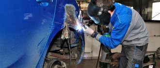
The entry into the market of compact machines for semi-automatic welding and their high popularity have contributed to the expansion of the use of welding in almost all spheres of human life. Thus, with the help of semi-automatic, various car body repairs are carried out. Welding is also used in industrial or private construction. They are used to produce various metal structures.
In the process of working with the device, some components tend to wear out and become unusable. One of these components of this equipment is a sleeve for a semi-automatic welding machine. During operation, elements are subject to various external factors:
- High temperatures during welding.
- Drops of molten metal.
- Scratches.
- Various bends.
Inside the sleeve, its guides are abraded by the wire, which is fed to the welding zone. Naturally, all these influences adversely affect the device and disable it. Often, the sleeve for a semi-automatic welding machine is the first to break.
Modern manufacturers today offer two types of welding hoses. This could be a hose itself or a burner. However, the appearance of these products is no different from each other. Both of these names refer to the same accessory.
Thus, a semi-automatic welding torch-sleeve consists of three main elements. This is the burner itself, the hose, as well as connectors for connecting them. Unfortunately, it is now difficult to find sleeves for sale separately. But you can purchase almost all the components of the design or find analogues.
Diagnostics and possible malfunctions
All semi-automatic welding machines are equipped with operating and maintenance instructions , which describe the most common faults, their possible causes and solutions. Therefore, it is recommended to first diagnose the defective device using these instructions.
The owner and user of a semi-automatic welding machine should be aware of the main components of this unit.
You need to know them at least in order to be able to eliminate the most basic breakdowns of the device, for example, replace a blown fuse on the control board. And without knowing where the electronic unit is located, it is impossible to find the fuse. Of course, you shouldn’t take the device to a service center or call a repairman to your home because of such a trifle.
Main components of semi-automatic welding machine:
- power supply system;
- filler wire supply line;
- electronic unit control board;
- gas source;
- burner.
The welder needs to know not only the design of the torch, but also the operating principle (and location) of the remaining components of the welding machine.
Let us list the most common breakdowns of semi-automatic devices, which occur either in the mechanical part of the device’s design or in the electronic part.
Mechanical
It often happens that you cannot immediately understand what is happening with the welding machine and where to start looking for the cause. For example, it does not turn on at all or turns on but does not cook, and if it does cook, then the arc is unstable. In such cases, possible causes may be poor contacts, both in the electrical connections to the device and in the electrical devices in the unit itself.
A situation is possible in which the welding machine suddenly turns off during operation. One of the likely causes of such a nuisance is the activation of short circuit protection in the electrical circuits of welding equipment.
Another common malfunction of semi-automatic welding machines is overheating.
The reasons here lie either in poor-quality contacts , or in the current settings for the welding process (unacceptably high), or in worn-out parts. If the value of the welding current is not regulated, then the cause may be a foreign object getting inside the casing of the control mechanism , which interferes with the movement of the secondary coils of the regulator. In addition, wear of the regulator screw or a short circuit between its terminals is possible.
The absence of an arc in some cases is also the result of poor contacts in the cables and the connection point to the part being welded. There are problems with the feed of filler wire: the feed is delayed or strong friction occurs in the feed channel. This can occur when the clamping mechanism is weakened or its adjustment is incorrect.
In most cases, all of the above malfunctions can be easily corrected on your own, without the help of specialists.
Electronic
to independently repair the electronic board of the control system and the electrical circuit of the welding machine without any thorough knowledge in the field of electrical engineering and electronics due to the complexity of these components.
But still, knowledge of how the electronic part of the unit is diagnosed in order to identify faults will be useful to the user.
It is recommended to check electronics using a certain algorithm. Moreover, this must be done after one or another breakdown has not been eliminated as a result of diagnostic and preventive measures carried out in the mechanical part of the unit.
- First of all, all fuses in the system are checked.
- The control board is dismantled, the performance of the parts on it is visually assessed (soldering, integrity, appearance and other signs).
- If a visual inspection does not produce results, you should check the serviceability of the board parts with a tester, desoldering each of them in turn. After checking, the working electronic part is installed in place, and testing continues further.
Causes of malfunctions of semi-automatic welding machines and ways to eliminate them
Table 1. - Typical malfunctions in the operation of semi-automatic welding machines, probable causes of their occurrence and methods of elimination
| Names of faults additional symptoms | Probable cause of the malfunction | Remedy |
| When the switch located on the welding torch is turned on, the arc does not ignite | — Lack of contacts in the welding circuit | — Check the reliability of the contacts and clean them |
| When welding, uneven feeding of the welding wire is observed | — Insufficient clamping of the welding wire in the feed mechanism drive rollers. — Excessive wear on the drive roller — Sticking of the welding wire in the channel or tip of the welding torch | — Adjust the pressure of the pressure rollers by changing the preload of the spring; — Replace the drive roller; — Clean the channel or tip: in case of excessive wear, replace it with a new one |
| The supply of shielding gas to the burner stops | — The welding wire in the cassette is mixed up — The gas valve does not work | - Unravel the wire. — Check the electrical circuit of the gas valve |
| The welding wire forms a loop between the feed rollers and the inlet fitting of the flexible hose | — The tightness of the gas path is broken — There is a large distance between the feed rollers and the inlet fitting of the flexible hose | — |Restore the tightness of the gas path — Reduce the distance as much as possible |
| The nozzle and collet of the welding torch are energized | — The insulation between the burner and the nozzle is broken and splashes have entered. | — Restore the insulation to remove metal splashes. |
| The feed speed of the welding wire is not adjusted when the resistance is changed by the potentiometer | — The potentiometer is faulty. — No voltage feedback in the drive unit | — Replace the potentiometer — Check the quality of soldering in the drive unit |
| When the welding wire feed motor is running normally, the arc periodically breaks. | — Low feed speed of welding wire. — High welding current. | — Increase the feed speed of the welding wire. — Reduce the welding current |
Test questions and assignments:
1. Indicate the operating procedure on the semi-automatic welding machine PDG-502U3
2. List the technical characteristics of the semi-automatic welding machine PDG-502U3
3. Decipher the designation of the semi-automatic welding machine PDG-502U3
4. Explain the reason and how to eliminate it if “during welding there is an uneven feed of the welding wire”
LECTURE No. 19
Plan
1. Purpose, completeness and functional block diagram of the semi-automatic welding machine for flux-cored wire welding A-7652. Design and operational features of the semi-automatic welding machine for flux-cored wire welding A-7653. Operating procedure on the semi-automatic welding machine A-7654. Main technical characteristics of semi-automatic welding machines
5. Safety and fire safety when working on semi-automatic welding machines
Key words: welding; arc welding; semi-automatic welding; electrode wire feeding mechanism; flexible hose; nozzle; burner, cored wire.
Literature:
1. Goloshubov V.I., Welding power sources.-Kyiv, Aristey, 2005
2. Gumenyuk.V., A.F. Ivaskiv, A.V. Gumenyuk Electric arc welding technology - Kyiv: Certificate, 2007
3. Kitaev AM, Kitaev Ya.A. Welder's reference book. — M.: Mechanical Engineering
4. Shebeko L.P. Equipment and technology for automatic and mechanized welding. M: Higher School, 1986
1. Purpose, completeness and functional block diagram of the semi-automatic welding machine for welding with flux-cored wire A-765
Semiautomatic welding machine A-765 V 4 (Fig. 1) is designed for arc welding and surfacing with solid and flux-cored wire.|..
The semi-automatic welding machine provides mechanized wire feeding into the welding zone, the ability to weld in hard-to-reach places and service a large production area with little auxiliary time.
Complete set of semi-automatic welding machine A-765U4
The semi-automatic welding kit includes:
— feeding mechanism;
— a set of hoses;
- hand torches;
— power source (welding rectifier VS-600 with a separate control cabinet);
- figurine for welding wire;
- spare parts.
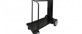
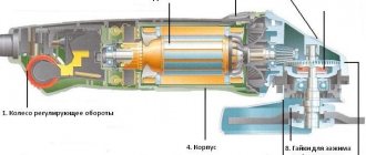
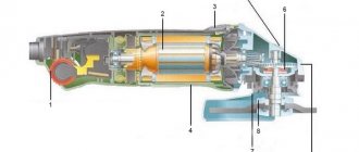
Fig. 1 - semi-automatic welding machine A-765:
1- feeding mechanism, 2- figurine for electrode wire, 3- trolley|
The functional block diagram of a semi-automatic welding machine for welding with flux-cored wire A-765 is presented in Figure 2.
Rice. 2 — Functional block diagram of a semi-automatic welding machine
for welding with flux-cored wire A-765
2 Design and operational features of a semi-automatic welding machine for welding with flux-cored wire A-765
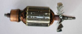
Feeding mechanism designed to feed welding wire into the arc burning zone. The feeding mechanism is driven by an asynchronous three-phase electric motor with a voltage of 36 V. The kinematic diagram of the feeding mechanism is shown in Fig. 3.
The wire feed speed is set using replaceable gears and is independent of the arc voltage. Flux-cored wire has low rigidity and can be crushed by the feed rollers if they are pressed too hard. Taking this into account, the welding wire is fed by two pairs of rollers: the upper ones are smooth and the lower ones are stacked with a groove.
All four videos are leading; this makes it possible to provide the necessary force for pushing the welding wire with a small clamping force, as a result of which the deformation of the flux-cored wire by the feed rollers is reduced.
All rollers are isolated from the body of the feed mechanism, allowing it to be installed directly on the product being welded.
The feeding mechanism is equipped with a special clamp for fastening it in the most convenient places for welding; In addition, it is symmetrical and can feed welding wire in two directions depending on which side the torch is connected to.
The torch (Fig. 4) serves to supply welding wire to the welding zone and supply welding current. The wire is fed through the guide channel, and the welding current through a separate channel. The welding wire is placed on a figurine mounted on a cart.
Fig. 3 - Kinematic diagram of the feed mechanism of the semi-automatic device |A-765:
I - electric motor; 2 - worm | |transfer; 3 — feed rollers; 4 -| variable gear|gear parts| wheels
Rice. 4 — Semi-automatic burner A-765:
1 - mouthpiece; 2 — start button; 3 - handle;
4 - current supply cable; 5 - flexible hose for welding wire
Main components of the welding machine and welding principle
A do-it-yourself semi-automatic welding machine, the circuit of which is not particularly complicated, consists of several basic elements:
- power supply;
- a device with the main function – control of welding current;
- sleeves;
- burners;
- clamps.
The power source can be a transformer, inverter or rectifier. The volume and price of the welder depends on which power source is selected. Inverter power supplies are called the best.
The electrical circuit of a semi-automatic welding machine provides that the type of welding affects the smooth operation of the equipment as a whole.
The operating principle of the device is to move and adjust the heating pad, control and monitor the welding process.
Also, the diagrams of homemade welding machines provide a certain sequence of operation. At the initial stage, preparatory purging of the system for further gas supply takes place. The arc power supply is started next. Then the wire is fed and the semi-automatic machine begins to move at a certain speed. At the end of the process, it is necessary to ensure the crater is welded and the seam is protected.
It should also be taken into account that the welding process is carried out in a special room using welding equipment.
Do-it-yourself semi-automatic welding requires mandatory compliance with safety rules. It is necessary to check the serviceability of all mechanisms and double-check whether the device body is grounded. During welding, do not lean or lean on the machine. If any problems arise with the device, you should immediately stop working and seek the help of a specialist.
Manufacturing of semi-automatic devices
Some elements of the device have to be redone, while others need to be made from scratch. Some of the upcoming work is highly complex and requires detailed consideration.
Transformer and control board
The transformer consists of two windings - primary and secondary. Moreover, they have a different number of turns of wire. First, current enters the primary winding and, due to the phenomenon of induction, the voltage on the secondary drops while the current increases. For a homemade semi-automatic device, you can use a ready-made transformer, for example, from a microwave oven, but you must remake it.
The fact is that this device produces significantly more voltage than is necessary for welding. In order for the unit to work well, it is necessary to calculate the transformer for the semi-automatic welding machine. Changes will be made to the secondary winding and the old one must first be removed. The thickness of the wire and the number of turns depend on the transformer being converted, and it is not possible to name their exact values now. When the required number of turns has been made, the winding is coated with a special current-insulating compound.
In addition, you will also need a control board, which should contain the following elements:
- Galvanic isolation transformer, also called master oscillator.
- Relay control unit.
- Feedback blocks.
- Thermal protection mechanism.
In addition, it is advisable to assemble a current regulator for a welding machine with your own hands in order to expand the functionality of the unit. To do this, you can use transistor circuits. When all the work is completed, all that remains is to connect the control unit to the power part of the device and connect it to the mains. After this, an oscilloscope is connected to the outputs of the product.
With its help, the frequency of electrical pulses is checked, which should be in the range of 40-50 kHz.
By changing the input voltage, it is necessary to configure the device so that a time interval of 15 μs is maintained between pulses. When the voltage is selected, the unit can be considered ready for operation.
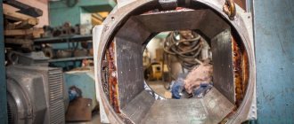
Case and cooling system
To accommodate all the elements of the unit, it is necessary to find a housing for it. The optimal solution here would be to make a box from sheet metal. First you need to install the transformers and then connect their windings. It should be noted that the primary coils must be connected in parallel, and the secondary coils in series.
It is worth paying attention to the cooling system of the semi-automatic machine, because during operation the inverter will get quite hot. To solve this problem, you can use fans from the PC system unit. They must be installed on both sides of the housing opposite the inverter.
Do not forget that warm air must be quickly removed from the case and for this purpose ten or even more holes should be drilled on the walls of the case.
Feed mechanism
If you don’t have a device from an old unit at hand, you can completely make it yourself . To do this, you will need two bearings of size 6202 and a small electric motor, for example, from car wipers. When connecting the feed mechanism to the welding unit circuit, you must make sure that the rotation of the electric motor is in the correct direction.
A roller with a diameter of 25 mm is installed on the motor shaft. The bearings are mounted on two plates, between which the electric motor and roller must be fixed. The entire feed mechanism is assembled on a textolite plate 5 mm thick. The spool of wire is mounted on a roller mounted on a textolite plate. Please note that the bobbin should sit on the shaft as tightly as possible.
If no mistakes were made during assembly of the structure, then the homemade unit will work for a long time and reliably.
Useful tips Connection diagrams Principles of operation of devices Main concepts Meters from Energomer Precautions Incandescent lamps Video instructions for the master Testing with a multimeter
How is semi-automatic welding carried out?
As in other types of welding, before starting work, you need to make sure that the parts have been pre-treated - degreased and cleaned. Before starting work, connect the ground cable to the welding table and check the extension of the welding wire. If the wire is longer, you need to cut it off with side cutters.
HELPFUL ADVICE.
It is important that the tip of the wire is sharp - then it will be easier to light the arc. During the welding process, before each new seam, the tip (or the resulting ball) of the wire will need to be bitten off - this will make the start of the new stage easier.
Like any type of welding, semi-automatic welding begins with ignition of the arc. To do this, the welding wire must touch the surface of the part being welded. We press the torch button - the supply of welding wire and shielding gas begins simultaneously.
The arc is ignited. The welding process is taking place. To extinguish the arc, you need to release the button and move the torches away from the work being welded.
The torch can be operated with one hand, but when using two hands the seam will be more accurate and control over the process will be more confident. You need to grab the burner with one hand, your index finger should be at the bottom of the start button. You can lean on your other hand with your leading hand - this will make it easier to control the distance to the surface to be welded and the angle of inclination, as well as make the necessary movements with the torch.
There is no universal welding torch angle that must be observed when welding. If we cook parts in the same plane and both parts are of the same thickness, then the burner can be held vertically. If the parts are different in thickness, then the tilt should be made towards the part with a smaller thickness. When welding two parts at an angle, it is more convenient to hold the torch at an angle of 5-25% degrees (from the vertical). The distance from the nozzle to the surface to be welded is from 5 to 20 mm.
The movement of the burner can be either forward or backward. When welding at an angle backwards. With this method, the depth of penetration and the height of the seam increases, its width decreases. When welding at an angle forward, the edges are better fused, the penetration depth is reduced, but the seam is wider. This method is good for welding metal of small thickness.
During the welding process, you will choose the most convenient and comfortable welding style for you - from the way you hold the torch to the parameters of the machine. Also pay attention to the sound of the arc - it will help you adjust the settings. Thus, a correctly installed arc has a smooth hissing sound. If you hear a cracking sound, then most likely there is an imbalance between feed speed and voltage, or poor contact in the welding area.
The influence of torch speed on seam quality
The quality of the weld also depends on the welding speed - the speed at which the electric arc passes along the welding site. The speed of the welding torch is controlled by the welder and affects the shape and quality of the weld. Over time, you will learn to determine the speed by looking at the thickness and width of the seam during the welding process:
The main malfunctions of the semi-automatic welding machine Luch Profi
24.08.2015
Luch Profi semi-automatic welding machines have firmly established themselves in the Ukrainian market of modern welding equipment. But, despite their reliability and practicality, like any complex equipment, they exhibit minor problems that the owner can successfully fix on his own.
In this article we will present the main problems with Luch Profi semi-automatic welding machines and methods for eliminating them.
The first problem happens quite rarely. Visible signs - the display and indicators do not light up, the fan does not spin. The first reason is simple - there is no voltage in the supply network. After making sure that there is voltage in the network, you need to make sure that the main fuse is intact. If the fuse is intact, the likely cause is failure of the protective circuits. To solve this problem you will have to contact a service center.
The second problem is more dangerous to the health and life of the welder. When the body of the semi-automatic welding machine is in operation, smoke comes out, and a burning smell is clearly felt. In this case, you need to urgently disconnect the device from the electrical network and contact a service center.
Quite often, when working, when touching the body of the Luch Profi semi-automatic welding machine, a small electric shock is felt. In this case, it is necessary to ensure reliable grounding of the device.
The next problem is that when working in semi-automatic mode, the wire does not feed when the button on the machine’s torch is pressed. One of the most likely causes is incorrect installation of the reel and threading of wire into the feed mechanism of the semi-automatic machine. In this case, it is necessary to check the correct filling and, if necessary, correct errors.
One of the reasons may be oxidation of the contacts of the KZ-2 quick-release connector for connecting the burner. In this case, it is necessary to disconnect the connector and wash the contacts with alcohol. The reasons that make it necessary to contact the Luch Profi semi-automatic repair service center are the breakdown of the button on the welding torch and the failure of the electrical part of the semi-automatic machine, which is responsible for controlling the wire feed and operating in semi-automatic mode.
When working with a Luch Profi semi-automatic welding machine, it is rare that the light indicators on the front panel fail. To replace them, you must contact the Luch Profi service center.
If the welding arc does not ignite when the machine is turned on, you need to check the quality of the contacts in the bayonet connections and, if necessary, clean them and degrease them with alcohol.
If the arc still ignites, but the electrode instantly sticks to the metal structure being welded during operation, it is necessary first of all to slightly increase the welding current. If the welding current adjustment is at maximum, then the probable cause is: reduced supply voltage of the electrical network. In this case, you will have to use specialized voltage stabilizers and generators for welding equipment.
The main reason for the frequent extinguishing of the arc during the welding process is the critically large distance between the electrode and the part being welded. In this case, it is necessary to reduce it slightly until stable combustion occurs.
It is worth noting that this troubleshooting guide can be applied to the Shyuan semi-automatic welding machine and others similar, made using inverter technology.
Read the continuation of the guide to troubleshooting semi-automatic devices Luch Profi at this link.
www.allteh.com.ua
Preparing the transformer
Your attention must be paid to the feeding mechanism. Using this device, the electrode wire must be fed. Due to the fact that this mechanism breaks down most often, high-quality calculations should be made. It is important to note that an increase in current in most cases leads to fire of the electrode. This causes severe damage to the product. But if the current is very weak, then it will not be possible to make a full-fledged unit. The resulting weld will be unreliable. Therefore, at this stage of preparation it is necessary to correctly perform all calculations.
Unit design
The operating principle of the inverter device is quite simple : current flows into the rectifier, after which a special filter smoothes out its pulsating voltage. As a result, you can get a direct current at the output, which is again converted into alternating current with the help of transistors, but its frequency is not 50 Hz, but 20 and higher.
All this allows homemade semi-automatic welding machines to compete with other types of welding equipment. However, their repair often becomes difficult due to the presence of several complex circuits, and in such a situation one cannot do without knowledge in the field of electronics. Since there is no need to use EMF frequency converters in a semi-automatic inverter unit, they are lightweight and have small dimensions.
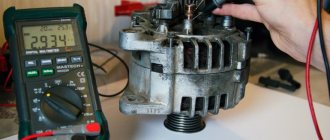
How to clean power elements?
The compartment where the electrical equipment is located should be cleaned using compressed air. But it is very important to exercise utmost care to avoid damage to electronic components and circuits.
If dust and dirt still remain on the surfaces after cleaning with a blow gun, you need to use a brush, preferably a nylon brush. And finally, purge again. Dirt and dust must be completely eliminated.
Burner design
There are many manufacturers of welding equipment, but the torch design is the same for everyone. They differ in materials, sizes, critical temperature and power, and mechanisms for supplying a protective medium (gas, flux).
Considering the design of the burner, it is worth noting that the main elements are:
- nozzle;
- holder;
- tip;
- insulating sleeve;
- base with handle.
Burner tips and nozzles are made from different materials and therefore have different service life. Copper is widely used, but the duration of work also depends on its quality. To increase service life, the nozzles are made of tungsten. But at the same time the price increases. The average operating time of such tips and nozzles is 200 hours.
Due to the frequent change of consumables, these elements are made quick-changeable so that the welder can replace them with his own hands in a short time.
The handle is made of heat-resistant insulating material that protects the welder from electric current. There is a button on the handle that turns on the supply of protective gas before igniting the arc.
The handle is connected to the welding machine through a supply hose, which contains the following:
- power cable;
- twisted wire feed channel;
- channel for supplying protective materials;
- cooling circuit;
- connector for connecting to the device and feed mechanisms.
The standardized hose length starts from 2.5 m and reaches 7 m. The length depends on the location and type of work performed. To reach the weld at a height without lifting the apparatus, the sleeve must be of maximum length.
But it is worth remembering that the excess, folded on the floor in rings, when voltage passes through them, works like inductive coils and gets very hot. As a result, a short circuit may occur.
Detailed rework algorithm
This modification method is quite complicated for the average user. However, it is quite suitable for the home craftsman who likes to assemble the instrument with his own hands and understands electrical circuits.
Required materials and tools
To assemble the unit you will need the following elements:
- inverter welding machine;
- a burner, as well as a special flexible hose, inside of which there are a gas pipeline, a wire guide, a power cable and an electrical control cable;
- mechanism for uniform automatic wire feeding;
- control module, as well as motor speed controller (PWM controller);
- cylinder with protective gas (carbon dioxide);
- solenoid valve for gas cut-off;
- coil with electrode wire.
To assemble a home-made semi-automatic welding inverter, the latter must generate a welding current of at least 150 A. But it will have to be slightly modernized, since the current-voltage characteristics (CV) of the inverter are not suitable for welding with electrode wire in a shielding gas environment.