Seeders for working with corn seeds are a row-crop type device. Such units are suitable for some types of legumes and sunflowers. When choosing, you should pay special attention to the ability of the equipment to optimally distribute seed throughout the bed. The yield of the crop will depend on the fulfillment of this requirement.
What is a corn seeder
A corn seeder is equipment that sows seeds into the soil. Before their appearance, this was done manually: grains were scattered in the field, trying to fill empty spaces. However, it is impossible to sow evenly by hand. For this purpose, special equipment is used - mechanical seeders.
How does she look
The design of the corn seeder consists of the following parts:
- frame mounted on wheels;
- sections with seeds;
- seed storage;
- dosing devices.
Depending on the number of sections in the seeder models, the planting row is determined. To adjust it, just remove or add drums to the frame. The technology for planting various types of corn depends on this.
Reference! With cross sowing technology, when the seeder goes along and then diagonally or across the field, sections are removed from the frame.
All corn seeders come in 3 types:
- universal - they work using seeds of various crops, but do not add fertilizers;
- combined - add seeds to the soil along with fertilizers;
- special - use only 1 type of seeds.
All devices consist of the following sections:
- compartments for seeds (usually 1-2);
- a mechanism that closes furrows;
- coulter, with the help of which grooves are made in the ground with the same depth;
- a sowing apparatus that delivers seeds in uniform portions into special seed tubes.
Principle of operation
Each seeder has a similar operating principle:
- Seeds are fed into the machine.
- Placed in the soil at the required depth and at an equal distance from each other.
- They are sealed using a special mechanism.
A pneumatic mechanism is used to crush and remove lumps. To be able to use the seeder on a problem field, crop residues are cut with special discs. After this, the skid coulter enters the ground without problems.
This is interesting:
What is a garlic seeder?
Technology for planting potatoes with a walk-behind tractor
Types of seeders and their design
Types of equipment differ in size, design and sowing methods. If large seeders are suitable for large farms, then in the garden a attachment for a walk-behind tractor is sufficient.
Trailed/mounted
According to the method of attachment to the equipment, trailed and mounted seeders are divided. The former require less productive machines to operate. For example, a tractor with a power of 45–60 hp. With. or seeding devices Kinze 3000, MT-8, YP-1630F, which have a power of 80 hp. With. They are aggregated with an eight-row YP-825 130 liter seeder. With.
Attachments are used to work with productive machines of at least the second class and tractors with high power (250–320 hp and 200–220 hp).
Mechanical/pneumatic
Corn sowing occurs in a dotted manner. In this case, seeders have a pneumatic or mechanical mechanism.
Mechanical seeders are gradually becoming obsolete and disappearing into oblivion; in many countries they have already been discontinued. To change the types of seeds, you have to completely dismantle the working panel and adjust the row spacing in a new way. There is simply not enough time for such a procedure.
Pneumatic corn seeders have a more advanced design, which includes:
- lump remover;
- furrow filler;
- compaction wheel;
- wedge tip;
- skid opener.
Her labor productivity is much higher with minimal time investment. Fertilizers are added along with the seeds. Among the significant disadvantages are:
- high price of the seeder;
- insufficiently effective work on problematic grounds;
- impossibility of use in fields where there are a lot of roots in the ground.
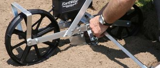
Manual/for walk-behind tractor/for special equipment
Manual devices are one of the most popular for sowing corn in small areas. Used in medium and small farms. They are characterized by high productivity: 0.5 hectares are sown in one day, provided that the land is prepared. They operate using a seed disc or plate at the bottom of the seed tank.
Seeders for walk-behind tractors allow seeding to be done in even steps in each row. To use them, holes are made in advance at a selected distance. Use devices only on loose and soft soils. Do not use on clay and heavy soil. The simple design is too heavy and bulky.
Seeders for special equipment are multifunctional. With their help, several types of corn are sown at once, simultaneously covering the maximum number of rows, the seeds are distributed over the marked holes, they are fertilized and covered with soil. This equipment has large dimensions and weight; it is used only on tractors and other machines with a power of 45 to 320 hp. With.
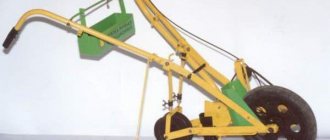
Rice.
1. General view of the SKNK-6 seeder: The seeder is supplied with eight sets of discs for sowing calibrated corn seeds of six fractions. One set is designed for sowing pea seeds and two for sowing soybean seeds.
Fertilizer sowing devices are also mounted on the beam, receiving movement from pneumatic support wheels. The seeder is equipped with a foot board for the seeder, light reflectors and an electric alarm for remote communication between the seeder and the tractor driver.
For square-cluster sowing of corn, the seeder is equipped with a device consisting of two tension stations, a reel with measuring wire, a roller and knotters. The seeder comes from the factory with a measuring wire 1200 m long, on which the stops are located at a distance of 140 cm from one another (for inter-holes 70 cm). To obtain nest spacing of 60 and 90 cm, measuring wires with a stop pitch of 120 and 180 cm are required. Dotted sowing is carried out without measuring wire. The seeder kit includes two markers (left and right), interlocked with a chain.
Seeders of the SKNK type are aggregated with medium-power tractors of traction classes 9-14 kN.
The working process of the seeder for square-cluster sowing proceeds as follows. When the machine moves with the working parts engaged, the sowing disks of the devices located at the bottom of the seed jars rotate and the seeds fill the cells of the disks. The cells are located along the periphery of the disks, and one grain falls into each cell. Excess and incorrectly placed seeds are cleaned off with reflectors. The seeds remaining in the cells are fed by a disk to a hole in the cast-iron bottom of the apparatus and are thrown into the coulter body by an ejector.
The opener body is divided by a partition into two channels, closed at the bottom by valves. Using a special dividing device connected to the mechanism for transmitting movement to the sowing apparatus, the grains entering the coulter body are divided into two portions and fed: one portion into the left channel onto the left coulter valve, the other into the right channel onto the right coulter valve. When sowing seeds in nests, the valves are opened by knotter forks. When the front fork of the knotter is deflected (by the stop of the measuring wire), the left valves of the openers open and portions of seeds accumulated in the left channels are thrown into the furrows opened by the openers. The rear knotter forks are connected to the right opener valves. Therefore, the stop of the measuring wire (fixed motionless along the line of movement of the seeder), deflecting the front fork of the knotter after 70 cm (or 90) of the seeder’s path, will approach the rear fork. Under the action of the stop, it will deflect, open the right valves of the coulters, and the portions of seeds located on them will be thrown into the furrows. This is how seeds are sown with inter-nests of 70 cm using a wire with a distance between stops of 140 cm.
Simultaneously with the opening of the valves during nest sowing of fertilizers, the valves in the funnels of the coulters open, where fertilizers from the fertilizer sowing devices are supplied through fertilizer lines. In this case, the fertilizers accumulated on the valves are dumped into the furrow and placed in portions near the seed nests.
With row seeding, fertilizers are continuously dumped into the furrow, and a layer of soil is formed between the seeds and fertilizers. Seeds and fertilizers thrown into the furrow are embedded and rolled on both sides of the row using wheels of 6 sections.
When dotted sowing, the coulter dividers are secured with special clamps (or removed completely) so that the seeds are fed continuously into the coulter channels and from there into open furrows. The coulter valves are fully open and are held in the open position by the knotter forks retracted all the way back. In this position, the forks are secured with stops. To prevent the openers from clogging, the valves are usually removed.
Construction of the main components of the seeder. The main components are sowing sections, fertilizer sowing devices and a device for square-cluster sowing, a frame with wheels.
Sowing units. Each section consists of a seed tank, a sowing unit, a press wheel coulter, mechanisms for transmitting movement to the sowing unit, opening valves and adjusting the coulter stroke, as well as a parallelogram suspension for connecting the section to the main frame
The SKNK-6 seeder has six sections, the SKNK-8 has eight. Depending on the row spacing, the number of sections may vary. At the same time, the working width of the machine also changes, equal to the product of the number of sections and the row spacing. For example, on the SKNK-6 seeder, when sowing with row spacings of 70, 105, 140 and 210 cm, 6, 4, 3 and 2 sections are installed, respectively. The working width of the seeder at these row spacings will be 4.2 m. When sowing with row spacings of 60, 90, 120 and 180 cm and the same number of sections, the working width of the seeder will be 3.6 m.
The seed jar and sowing unit are a single unit. A jar (Fig. 2, a) with a volume of 13 dm3 is covered with a lid, which is held in the closed position by a spring. The sowing unit is located at the bottom of the can and consists of a housing, a replaceable sowing disc, a lining ring and a folding ring. The body has a cover in which reflectors with springs and an ejector with a regulator are mounted. A hinged ring is attached to the body, acting as the bottom of the device. This ring holds the seeding disc and backing ring in the housing. In the assembled position, the folding ring is secured to the body with spring-loaded latches (not shown in the figure). The assembled device is installed on the section bracket (Fig. 2,b) and secured to it with a bracket (Fig. 2,a). The sowing disk has two grooves for installation on the protrusions (Fig. 2, b) of the bevel gear of the device drive. This gear is in constant mesh with a bevel gear mounted on the transmission shaft. The roller is driven by a sprocket connected by a chain to the press wheel sprocket.
When the sowing disc rotates, seeds fall into its cells. Reflectors (Fig. 2, a) slide over the surface of the disk, clean off excess seeds and allow only those that fit completely into the cells to pass through. When the cells are above the window in the folding ring, the end of the ejector throws the seeds into the cavity of the coulter body.
The bracket (Fig. 2, b) is installed above the opener and is a cast figured part made of gray cast iron. The transmission to the seeding unit (bevel gear pair, roller and sprocket) is mounted on the bracket body. The bracket is secured with a flange to the flange of the opener body.
Rice. 102. Units of the sowing section
The section coulter serves to open the furrow, accumulate nests of seeds and mineral fertilizers, feed them into the open furrow (during nest sowing) and seal them with soil. When the nest-forming device is turned off, the seeds are sown in the furrow in a dotted line.
In the seeders under consideration, the coulter is combined, skid-type and consists of a skid (Fig. 2, c) attached to a cast-iron body. In the front part of the runner there is a funnel for fat. The body cavity is divided by a partition into two channels, closed at the bottom by valves. In the upper part of the housing, a changeover valve-divider is installed on the axis, which divides the seed flow into two equal portions. These portions enter alternately (depending on the location of the divider) into the right and left channels of the opener body.
The valves are connected by rods to levers, which are pivotally connected by a common axis to the front wall of the housing. On the rear wall of the housing there is a rocker with adjustable thrust bolts. The entire considered system of levers forms a mechanism for opening valves and rearranging a two-bladed divider valve connected by rods to the square shafts of the knotters.
The mechanism works as follows. When the front fork of the knotter is deflected (under the influence of the stop of the measuring wire), the square shaft connected to the mechanism rod rotates. This rod, in turn, rotates a three-arm lever associated with the left valve rod. As a result, the left valves of all openers open. The mechanism for opening the right valves when the rear forks of the knotters are deflected works similarly. When the left valve opens, the lever simultaneously raises the left arm of the rocker arm. In this case, the divider valve rotates and is installed in a vertical position. Further movement of the valve around its axis is carried out under the action of a spring; The upper blade of the divider covers the left channel of the opener body, and the lower blade covers the right channel. The next portion of seeds will accumulate on the lower blade of the divider until the right opener valve opens. In this case, the right lever will move the divider to its original position, and a portion of seeds from the lower blade of the divider along the right channel of the opener will enter the furrow. Seeds will now accumulate on the lower divider blade, covering the left cavity. The return of the levers to their original positions occurs under the action of springs located on the right and left sides of the opener. The rods are connected by levers to valves in the fertilizer funnels. Therefore, simultaneously with the opening of the coulter valves, the valves in the funnels open and the fertilizers accumulated on the valves are placed in nests near the seed nests.
When dotted sowing, the mechanism for opening the valves and turning the divider is turned off, and the seeds are sown in a dotted line, and fertilizers are placed in continuous rows in a furrow with a small layer of soil.
The press wheel has two functions. It compacts the soil in the row area and drives the sowing unit through a chain drive. The wheel is of a welded structure and is formed by two conical rims (Fig. 2,d), connected by arcuate strips and a hub. The hub is rigidly mounted on a shaft rotating in bearings 8. The bearing housings are mounted on a frame pivotally connected to the coulter body. Strips are welded to the frame, to which the lower end of the rod of the mechanism for adjusting the depth of stroke of the coulter is hingedly attached. The upper end of the rod is passed through the hole in the crack of the bracket for attaching the rod to the square of the seeder frame. A spring is attached to the rod. Its tension is changed by rearranging the screw (cotter pin) in the holes of the rod. The coulter is set to a given depth of travel by rearranging it relative to the reference plane of the wheel. To do this, a link with holes is hinged to the coulter body and passed through a guide bracket.
Scrapers are used to clean the wheel rims from adhering soil. It is also possible to install rubber tires on the press wheels. In this case, the scrapers are removed.
A sprocket is fixed to the wheel shaft, from which sprocket 6 (Fig. 102.6) of the seeding unit drive shaft is rotated by a chain.
Each sowing unit is hinged to the main beam of the frame using a four-link parallelogram suspension.
The left sections differ from the right ones in the location of the fertilizer funnel. In the left section, funnel 15 (Fig. 2, c) is located on the left of the skid, and in the right section - on the right.
Rice. 3. Tukovysevaclation apparatus ATD-2: a — details; b - general view; 1 — level indicator; 2 - cover; 3—jar; 4 - seeding regulator; 5 — sowing disc; 6—funnel; 7 — bracket; 8— roller; 9 - pin: 10 and 11 - gears; 12 - turner; 13 - belt; 14 - bevel gear; 15 - vas deferens; 16 - hook.
Tukov sowing machine. SKNK seeders are equipped with ATD-2 fertilizer sowing devices of the disc-scraper type. Each unit supplies fertilizer to two sowing units. The design of the ATD-2 apparatus and the process of its operation differ significantly from the design and operating process of the AT-2A apparatus used on potato planting machines.
The general view of the apparatus and its main parts are shown in Figures 3, a and b. A fertilizer jar with a volume of 30 dm3 is closed with a lid. There is a fertilizer level indicator inside the can. The bottom of the jar is covered with a belt with two windows for the release of fertilizers.
A flat sowing disc is mounted inside the can, which is connected by a bushing to a spur gear (45 teeth). A turner with sheet steel fingers is bolted to the disk. The disk is connected to the wheel by a safety clutch, which is activated when foreign objects enter the jar along with fertilizer. The coupling is mounted in the internal cavity of the gear wheel.
The movement to the sowing disc is transmitted by a chain drive from a sprocket on the axle of the support-drive wheels through the sprocket of the intermediate shaft on the seeder frame and the sprocket mounted on the roller. On the same roller there is a bevel gear connected to the bevel ring of the double gear. The cylindrical ring gear of the wheel is engaged with the gear wheel. The axis of rotation of the wheel is a pin with a conical head. The transmission mechanism is mounted in a cast iron bracket, which has hooks for fastening to the seeder frame.
This is how the device works. When rotating, the sowing disc carries the bottom layer of fertilizer and delivers it to the sowing windows in the belt. The amount of fertilizer supplied to the windows is determined by the position of the seeding regulator guides. Through the windows of the belt, fertilizers enter the funnels of the fertilizer pipes and then into the funnels of the coulters. The agitator prevents arching and ensures the supply of fertilizer to the disc, and also cleans the sowing windows (when working with wet fertilizers). As the cans are emptied, the level indicator lowers. The protruding end of the indicator bar shows the level of fertilizer in the jar. When it drops so much that its ring rests against the handle of the jar lid, you need to stop working and pour a new portion of fertilizer into the jar.
Frame and support wheels. The frame is welded and consists of a front main beam and a rear angle, connected by three pipes. The SKNK-8 seeder has an elongated frame for attaching eight sections of working bodies and four fertilizer sowing devices. Therefore, the front frame beam of the SKNK-8 seeder is equipped with a sprengel to increase rigidity, which is attached to the beam strips with nuts and locknuts.
In the middle part of the main beam, a unit of channels in the form of a trapezoid is welded. The channels are connected at an angle of 65° and secured with a gusset. This unit is called a lock and is used to automatically connect the seeder to the tractor. In addition to the lock for the automatic coupler, there is a special welded frame that is installed on the tractor linkage rods.
A foot board is mounted on the frame of the seeder, consisting of two handrails, one step and two steps. The handrail posts are connected by braces to the front frame beam. Reflectors are attached to the outer pillars - red in front and yellow in back. Light from vehicles moving towards the seeder is reflected at night by this device and indicates the dimensions of the seeder during transportation.
Markers are hingedly attached to the frame brackets.
The support-drive wheels are pneumatic and mounted on separate frames, bolted to the brackets of the fertilizer sowing apparatus. The sprockets (2= 11) of the chain transmission to the shafts of the devices are fixed on the wheel axles.
Device for square-cluster sowing. As already noted, the device includes two tension stations, a spool of measuring wire and knotters.
Tension stations (tempering stakes) left and right are designed for securing and tensioning the measuring wire. Each station is made in the form of a rod (Fig. 4, a), in the lower part of which there is a frame with teeth and a stop.
A drum is fixed to the rod, and a braking device is mounted inside it, thanks to which a force of approximately 220-260 N is required to unwind the cable from the drum; The cable is wound when the drum rotates freely.
One end of the cable is fixed to the drum, the other is passed through the eye of the leash and connected with a hook to the stop of the measuring wire.
The drum is mounted not on the rod itself, but on a tube bracket that sits loosely on the rod. Above the tube, a locking device is placed on the rod, consisting of two jaws, between which a pawl is hinged. The locking device is secured to the rod by the handle so that the pawl can engage the teeth of the drum ratchet, preventing it from rotating. During work in the field, the pawl is removed from the ratchet by turning the drum with a leash around the rod under the influence of a measuring wire. In this case, the increased tension of the wire overcomes the braking resistance (220-260 N) of the drum, and it turns, unwinding the cable (rope). The right and left tension stations differ from each other only in that on the right, the drum with a leash can only rotate around the rod to the right, and on the left, only to the left (due to the protrusion on one cheek of the locking device).
Rice. 4. Units of the device for square-cluster sowing: a - tension station: 1 - rod; 2 and 3 - cheeks; 4— dog; 5 - drum; 6 - leash; 7 — hook; 8 - cable; 9 — emphasis; 10 — frame tooth; 11 — frame; 12 - tube; 13 — handle; b - coil with measuring wire: 1 - axis; 2 — roller-stacker; 3 - coil; 4 - coupling; 5 — asterisk; 6 - axis; 7 and 11 — brackets; 8 - shaft; 9 — asterisk; 10 — tension sprocket; 12 — wing nut; c — knotter: 1 — corner; 2—folding hinge; 3 - spring; 4 - roller; 5 — lever; 6 - fork; 7 and 11 - thrust; 8— bracket; 9 and 10 - square shafts; 12 — ejector; 13 - pin; 14 - beam; 15 and 20 - dogs; 16 — thrust; 17 and 19 — levers; 18 — bracket.
A reel (Fig. 4,b) with measuring wire is mounted on the left side of the seeder along with a device for winding and unwinding the wire. The coil is mounted on an axle and is secured with brackets to the frame beam. In addition, the axle is fitted with a bracket on which an axle with a helical groove and a measuring wire roller is mounted. A brake clutch is mounted inside the reel, which regulates the unwinding of the wire from the reel. The wire tension can be adjusted by screwing or unscrewing the nuts. When screwing the nuts, the wire tension increases, and when unscrewing it decreases.
The coil is driven into rotation from the sprocket of the intermediate left shaft by a chain placed on the sprocket and tension sprocket. The sprocket is mounted freely on the shaft and is engaged in operation by the end coupling at the end of the shaft. The shaft is driven by a chain transmission from a sprocket on the axis of the left support-drive wheel.
To unwind the wire, the end of it is transferred from the spool to a roller and attached to the hook of the tension station cable. When the unit moves with the seeder lowered into the working position (and the markers raised into the transport position) along a strictly hung line, the wire will be unwinded from the reel and laid on the field, the roller playing the role of a guide. After unwinding (at the end of the run), the wire is separated from the spool. To prevent the coil from rotating idle when the seeder is operating, the gear is turned off by turning the sprocket end coupling over with its teeth facing outward.
To wind onto a reel, the end of the wire is unhooked from the cable of the tension station, attached to the reel and thrown onto the roller. Then the chain drive is turned on to the reel, engaging the sprocket with the clutch. When the unit moves, the wire will be wound onto the reel, and the screw groove on the axis ensures that the wire is laid (by a laying roller) on the reel in even rows.
Under the action of the measuring wire stops, the knotters turn on mechanisms for opening the coulter valves and rotating the seed flow dividers every 70 cm of the seeder path (with a stop pitch of 140 cm). The seeder is equipped with two knotters - right and left.
The knotter is a prefabricated unit consisting of a number of parts mounted on an angle (Fig. 4, c). On this corner there are front and rear levers with forks in which the measuring wire is located. The levers are mounted on the outer ends of the rollers, passed into the holes of the brackets. At the other ends of these rollers there are levers connected by rods to the levers of the front and rear square shafts. The mechanisms for opening the valves and rotating the coulter dividers are connected to these shafts. Spring tension holds the levers with forks in a vertical position. Under the action of the stops of the measuring wire (when the seeder moves), the forks are deflected and the rods turn the square shafts, and, consequently, the mechanisms for opening and turning the valves. Brackets limit the upper position of the measuring wire.
A mechanism for dropping the measuring wire is also mounted on the corner. The need for this mechanism is due to the use of a diagonal method of transferring the measuring wire. With this method, during operation of the seeder, the angle of deviation of the wire from the direction of movement gradually increases as the unit approaches the end of the headland. Therefore, towards the end of the rut, the tension of the measuring wire increases; at the same time, the pressure on the ejector mounted on a bracket in front of the knotter increases. When the pressure reaches a certain value, the tension of the springs is overcome, the ejector rotates around the pin and retracts the front pawl holding the front fork. The pawl is blocked by rods with the rear pawl. Therefore, when the ejector mechanism is activated, both forks fold back and release the measuring wire.
Electrical alarm system. The system is designed for remote communication (by sound signal) of the tractor driver with the personnel servicing the seeder. The system includes a push-button switch, plug and cable.
The push-button switch is mounted on the support bracket of the seeder footboard (near the right handrail). One end of the cable is connected to the switch terminal, and the other end with a plug is plugged into a socket on the rear wall of the tractor cab. During operation, the cable is attached with a clamp to the bolt of the marker blocking bracket (SKNK-6 machine) or to the frame suspension triangle (SKNK-8 machine).
Preparing seeders for work and basic adjustments.
Preparing seeders for work includes performing the following operations: checking the completeness and correct assembly of the machine; arrangement of sections at a given row spacing; installation on a given sowing pattern (square-cluster or dotted); checking and adjusting the opening mechanisms of opener valves (during nest sowing); installation of sowing and fertilizer sowing devices at a given seeding rate; checking tension stations; installing markers, attaching the machine to the tractor and running it in.
Assembly and quality checks are carried out in accordance with the factory manual. In this case, you should pay attention to the strength of bolted connections and the serviceability of all components and mechanisms.
Arrangement of sections. As already noted, seeders can sow corn and seeds of other row crops with main row spacings of 60, 70, 90 and 105 cm, as well as larger widths that are multiples of the main ones. The most common scheme for sowing corn is the square-cluster method 70X70 cm or dotted, with the same row spacing.
Regardless of the specified sowing pattern, the sections are placed in a single sequence with the machine raised and installed on stands. Remove the pressure rods of the coulters and loosen the parts securing the sections to the seeder frame. Next, remove the transmission chain to the measuring wire unwinding mechanism. Then the sections are moved and set to the required row spacing symmetrically relative to the middle of the seeder frame. First, the new location of the section is marked from the middle of the seeder frame (as when installing the coulters of a row seeder).
Installation of the seeder for a given sowing pattern. The design of the seeders makes it possible to obtain (with appropriate measuring wire) square-cluster sowing with distances between the centers of the nests of 60, 70 and 90 cm and additionally 120, 140 and 180 cm. For sowing with nest spacing of 140 cm, the rear forks of the knotters are turned off, i.e. the seeder Only works with front forks. In this case, the rear forks are lowered, and their forks are moved to the rearmost position and tied to the brackets. In addition, the dividers are removed and, instead of them, special guides made of sheet steel 0.5-1 mm thick are installed in the housings so that they overlap the right channels of the openers. To obtain nest spacing of 60 and 90 cm, the distance between the knotter forks is also set to 60 and 90 cm.
When setting the seeder for dotted sowing, both forks of the left knotter are retracted to the fullest and secured with special stops. In this case, the dividers in the coulter bodies should be located in the middle of the chamber so that the seeds can flow freely into both channels. In the middle position, the dividers are also secured with special clamps. If there are no special clamps, if the valves do not open sufficiently, it is better to remove the dividers and valves. The distances between grains during dotted sowing are established by selecting gear ratios for the sowing devices. Replaceable sprockets are installed on the axles of the press wheels and on the drive shafts of the devices. By installing sprockets with a number of teeth r - 6, 8, 10 and 11, twelve rotation speeds of sowing discs are obtained with estimated distances between seeds from 55 to 16 cm.
Checking and adjusting valve opening mechanisms. The mechanisms are checked and adjusted for the size and simultaneity of opening of the valves on each opener separately. To check, pull the knotter forks one by one back until they stop in the brackets and secure them with the same stops as when setting up for dotted sowing. When the forks are deflected, all valves should open simultaneously, and in the retracted position - to the same size (flush with the rear edge of the coulter skid). The opening of one or another valve is regulated by changing the length of the corresponding rods of the mechanism.
On each opener, check and adjust the gaps between the bolt heads (Fig. 3, b) and the levers. In the lowered position of the rocker arms, this gap should be 1-3 mm
When nest sowing of fertilizers, check the correct placement of the valves in the funnels. When the knotter forks are retracted to failure, the valves should be positioned vertically.
Installation of seed sowing and fertilizer sowing devices at a given rate of sowing seeds and fertilizers. Only calibrated corn seeds (six fractions) are used as seed material. Sowing discs are selected from available kits for a given number of seeds per hectare and per nest, taking into account the recommendations given in the factory instructions for selecting the gear ratio for seeding units. Using replaceable sprockets g=6, 8, 10 and 11, you can get twelve gear ratios on the drive shafts of the sowing devices - from 0.13 to 0.458. With an increase in the gear ratio, the rotation speed of the discs increases and the number of seeds sown per hectare and per nest increases accordingly.
Pre-selected discs are checked on the seeder by rolling it on a flat area. Seeds (at least 1/3 of the jar volume) of the fraction for which the discs are selected are poured into the jars. On a flat area, stretch the measuring wire and roll the seeder without deepening the coulters 50-100 m. If the resulting seeding differs from the required (according to agricultural requirements), select a new disk or set a different disk rotation speed.
Fertilizer sowing devices are set to a given fertilizer seeding rate in approximately the same way as AT-2A devices using a seeding regulator.
It should be borne in mind that new seeders coming from the factory are installed for row seeding of fertilizers. The set of parts included with the machine contains everything necessary for converting the openers to nest seeding of fertilizers.
Checking tension stations. Tensioning stations are checked for drum braking force. Any dynamometer can be used for this purpose. When the pawl is tilted up, the drum should operate (rotate) with a force of 220-260 N.
Setting markers. The marker reach, i.e. the distance from the outer coulter to the marker disk, is set in accordance with the row spacing and the alignment of the tractor wheels. The offset values of the left and right markers are determined either by calculation or according to the factory instructions.
Attaching the seeder to the tractor and running in the unit. Tractors must be equipped with a connecting frame for automatic connection to the seeder. To ensure the longitudinal stability of the unit, it is necessary to balance it with weights (on the front wheels and side members in accordance with the factory recommendations). The tire pressure of the tractor wheels should be 0.17 MPa.
The seeder is mounted on a tractor on a flat area, having previously positioned its wheels to the required track width.
After installing the auto-hitch frame on the tractor rods, move the tractor slowly back until there is tight contact. touching the frame with the lock on the seeder. Next, the hydraulic mechanism of the tractor is turned on for lifting, and the seeder rises to the transport position. In this case, the auto-hinging frame slides along the sidewalls of the lock channels until the frame is fixed by the pawl in the lock. After manually checking the strength of the frame lock in the lock, lower the seeder and pin the pawl.
After mounting the seeder on the tractor, install and adjust the mechanism for locking and switching markers. When properly locked, the marker installed in the working position should not hang.
A new or repaired seeder is rolled over a measuring wire stretched in a field or on a flat area without seeds for about 1 hour.
During the running-in process, the smooth operation of all mechanisms is checked. After running-in, inspect the seeder again, tighten the fastenings and eliminate any detected faults. The units are finally adjusted to specific operating conditions in the field during a test run.
Basic adjustments of seeders. SKNK type seeders provide the following adjustments. 1. Depth of seed placement (on each opener) - by rearranging the section press wheel relative to the reference plane of the opener. 2. Simultaneous sowing of seeds and opening of the valves of all openers - by changing the length of the rods of the valve opening mechanism. 3. Norms for sowing seeds and fertilizers. 4. Positions of the knotters on the frame (by moving them along the bracket) to obtain even transverse rows during nest sowing; the nests should be located behind the stops of the measuring wire by 10-12 cm for the SKNK-6 seeder and 16-18 cm for the SKNK-8 seeder. 5. Forces on the knotter forks (the forks must deflect with a force of no more than 100 N) - by moving the ends of the springs into the corresponding holes in the stops. 6. Lengths of rods of the automatic measuring wire ejector for simultaneous opening of the front and rear hinges and changing the position of the ejector on the bracket if the front hinge does not open. 7. Lengths of markers to obtain equal widths of butt and main row spacings.
Assessment and quality control of sowing. During the first three or four passes, the operation of all components and mechanisms of the seeder is checked and adjusted, if necessary, in relation to sowing conditions. In addition, the quality of sowing is checked and periodically monitored during further work.
The main indicators of the quality of square-cluster sowing: the depth of seeding, the grouping of nests and the actual number of seeds in the nests, the straightness of the transverse rows of nests within one aisle and their combination in adjacent aisles, the consistency of the width of the main and butt rows.
The depth of seed placement is checked as follows: carefully open several nests in each of the six rows, and place a rail horizontally above each nest (across the row); then, using a vertical ruler, measure the depth of the seeds (the distance from the seeds to the staff). If the average seed depth differs from the specified depth by more than 1 cm, adjust the depth of the coulters.
The grouping of nests and the number of seeds in them are checked simultaneously with checking the depth of seed placement. For a more accurate check, count the number of seeds in at least ten nests for each of the six rows. The length of the nests is measured with a ruler. If the number of seeds in the nests differs from the norm, you need to check the correct selection of sowing discs. Inaccurate seeding can also result from poor seed calibration and unclear operation of the valve opening mechanism.
Stretching of the nests (more than 7 cm) may be a consequence of improper opening of the valves, as well as clogging of the openers.
The straightness of the transverse rows is checked by opening the nests and installing small pegs in their centers. By pulling the twine over the pegs, the displacement of individual nests from a straight line within one pass is determined. If one or more nests are displaced from the common line by more than 5 cm, adjust the valves of the corresponding openers.
The coincidence of transverse rows in adjacent aisles is checked in the same way (with twine). At the same time, measure the distance from the twine to the nearest stop of the measuring wire (seeding advance). The correct arrangement of transverse rows in adjacent aisles is achieved by adjusting the position of the knotters.
Indicators of the quality of dotted sowing will be: uniformity of seed placement depth and consistency of distances between them.
Popular brands
Let's look at the main characteristics of well-known models of corn seeders.
Gaspardo
The Italian unit is distinguished by its original placement of seeds in the soil . The equipment has a double grain switch with adjustment to sow processed seeds and irregularly shaped or sized seeds. The seeding depth is adjusted mechanically using a special handle. The seeds are pressed into the soil in a stainless steel circle. This solution ensures uniform growth of cereals.
Interesting! The model has a seeder module setting for various types of crops and land. The gearbox of the gearbox allows for simple and quick installation.
MT-8 has a fertilizer sowing system with dosing capabilities from 50 to 700 kg/ha.
The price of the model is 450–1400 thousand rubles. According to reviews, this is one of the most popular brands among its peers. The only one with special seeding sensors, it practically does not break. Parts are sold at low prices.
Amazone
The German manufacturer has two models of machines for sowing corn: ED and EDX. The second is intended for growing in large areas, where time is very important. The operating speed of the equipment is 15 km/h.
ED models are available with 4, 6, 8 or 12 rows. Seeds are placed in the soil according to the principle of air suction. The vacuum pulls the grains into the holes and places them in the ground. The seeders are equipped with a central seeding drive. The gear train has 36 steps - depending on the discs used, intervals from 2 to 53.8 cm are obtained.
The price of the device is 2.5–10 million rubles. According to farmers' reviews, the brand is considered one of the most reliable. There are practically no negative aspects mentioned, apart from the high price.
"A red star"
Ukrainian produces a model for sowing corn SUPN-8, which places fertilizers in a special furrow, sprinkles them and produces high-precision sowing of corn seeds, creating optimal conditions for them to grow. Seeder productivity is 3.36–3.9 ha/h at a flow rate of 2 to 16 kg/ha.
Cost - 295–599 thousand rubles. The positive aspects include a fairly low price and cheap spare parts. Among the disadvantages are frequent breakdowns.
"Lidselmash"
The Belarusian manufacturer produces the SPCh-6 model with precision seed sowing and use for row crops. Like SUPN-8, it allows you to place fertilizers in the furrows. The maximum number of rows is 6 (with a storage volume of 20–30 liters, a flow rate of 3-7 pieces/m and a furrow width of 45–70 cm).
Price - from 260 thousand rubles. Among the advantages, farmers note the relatively low price and the availability of a transport device. The disadvantages are the inability to use fertilizers during sowing, the device’s “dislike” for wet weather and the ability to work only on perfectly prepared soil.
John Deere
The American company produces model 7000, which operates on a mechanical principle. The seeder weighs 3.85 tons. The unit has an 8-row structure with a storage volume of 56 liters. Price - from 1.5 million rubles.
There are practically no negative reviews of John Deere seeders on the Internet. Most owners of this model have no complaints about it, but point out the high price and the fact that in rainy weather the device becomes clogged with stuck damp earth.
How to make a do-it-yourself corn seeder
A DIY seeder is an easy-to-use piece of equipment. The selection of materials for the device depends entirely on the designer’s flight of fancy, although there are basic principles.
What to use to create a design
To make a seeder with your own hands, it is important to know its design. You will need:
- steel sheets 2.5 mm thick and about 1 m2 in size;
- latch, furniture hinge and glass cover;
- vomer;
- galvanized steel box (seed container)
- M6 screws and M5 bolts;
- 1-2 wheels;
- brush.
Seeder components and step-by-step instructions
For a homemade seeder you will need:
- a hopper into which seeds are loaded;
- one or more wheels for moving the seeder;
- grain dispenser sleeve;
- frame for mounting distribution mechanisms and wheels;
- blindly drilled holes along the edges of the seed sleeve through which filling occurs.
Creation instructions:
- Drill holes in the sowing shaft in 3 rows with different diameters that correspond to the types of seeds.
- Take a seed container and adjust the frame according to its size.
- Insert the sowing shaft into the holes with a diameter of 28.05 mm drilled on the sides from the bottom.
- Secure the grain container with bolts and attach a brush above it to regulate the sowing density.
- Adjust the correct configuration for the trapezoidal container with truncation and required holes.
- Attach the lid to the top of the tank using a furniture hinge and a special latch.
Homemade corn seeder.
The working process
When the unit starts, the fan is simultaneously brought into operation and blows air into the seeding module. A distribution disc rotates inside it, to which the seed is attracted. The seeds are fed to the disc using a tedder. The seed disc has holes into which the seeds flow. In parallel with this process, furrows are formed. The opener is responsible for this procedure.
Having flown out of the holes of the distribution disk, the seeds fall into the formed furrow. Mineral fertilizers are also placed there. The furrow is covered with earth and rolled on top with a special compaction wheel.