Parts for extruder assembly
How to assemble a Mosaic printer from a set of parts from MakerGear is described in the article Assembling a 3D printer with your own hands. You probably noticed that the device of a 3D printer is discussed in detail, but there is no talk about the print head. This is the topic of today's conversation.
We will look at the types of extruders and methods of manufacturing individual parts of this complex mechanism in order to understand how to make an extruder with your own hands (video about drilling a nozzle at the end of the article).
Extruder for 3D printer: design features
A 3D printer has its own characteristics, like any device. If we talk about an extruder, its design can be divided into two main components:
- Cold-end. Pushing mechanism. It consists of a gear and a pinch roller that grip and push the filament forward. The gear is driven by a small motor through a special shaft. The pressure roller is spring loaded. This arrangement of the unit allows you to work with rods of different thicknesses.
- Hot-end. Heating part. It consists of: a nozzle, a heater, a heating sensor and a thermal insulator. The latter plays the role of a cutting bridge. It traps excess heat so that the filament does not start to melt in the feed tube. A nichrome wire or a special plate with two resistors is placed on the heater.
The assembly may have a one-piece design where both components are installed one behind the other. This arrangement is called Direct Extruder. This scheme is found in a large number of modern printers. The second extruder option is Bowden Extruder. Here the cold-end and hot-end are located in different parts of the printer. The hot end is fixed in the Z-axis carriage, and the feed unit is mounted on the frame. They are connected to each other with a Teflon tube. This arrangement greatly simplifies the print head itself. It clogs less. But there are also disadvantages. The rod may simply get tangled or break off while traveling from the feed unit to the heater.
Extruder operation diagram
Interesting! There are more complex designs with paired print heads. They allow you to work with two filament strands at once. For the purposes of this article, we will talk about a simple extruder with one heater and a feed mechanism.
Recommendations for use
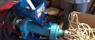
The grain extruder is installed on a flat, flat surface. It is advisable to use the device in a room with low humidity and good ventilation. The grain is fed evenly and constantly, otherwise the compartment with the press will be overloaded. To adjust the size of the finished granules, change the sieve or tighten the matrix bolt.
Finish the work by gradually reducing the speed. After each use, the device must be disassembled and washed to avoid clogging of the working and cutting units with particles of dried food.
How to choose a hotend?
It is worth noting that the extruder is a rather expensive part. Assembled, this spare part can cost $80–150. Moreover, the cost in Russian retail stores is not much different from that in China. It turns out that this is one of the most expensive components in the entire printing device.
That's why many 3D makers make homemade printers. They also assemble the extruder themselves, using open blueprints on the Internet. To assemble the printing unit correctly, you need to initially calculate what tasks it will solve. To do this, you need to evaluate several parameters of the future printer:
- Engine power. It directly depends on the size of the nozzle. If a 3D maker is going to make projects with greater detail, he will need a small nozzle and a powerful motor. Otherwise, the plastic may simply get stuck.
- Nozzle. As mentioned above, the diameter of the nozzle opening is selected based on the assigned tasks.
- Feed roller. This is a weak point in the printer. Often the roller slips and the filament does not flow. Printing defects appear. For example, PLA and ABS rollers interact very poorly with nylon thread.
- Extruder design. All components can be fastened into one unit by printing them on a 3D printer. Or cut it out of plywood. Both options are easy to do. However, a monolithic plastic structure will be stronger than a plywood box.
- Extruder type. It all depends on the experience of the printer and the tasks he will solve. The Bowden type extruder is said to be more accurate, but is a little more difficult to make. And in home-made entry-level designs, its advantages disappear. Direct does not print as accurately, but is easier to manufacture.
The situation with the hot-end is a little more complicated. There are two ways to go here. First: buy ready-made spare parts on the Internet, which is also not cheap. Second: do it yourself. To do this, you need to be patient and have the necessary components. We will provide more detailed instructions for assembling the hot end towards the end of this material.
Attention! If you don't want to make your own hot end, you can order one on E-bay. For example, a model from E3D. True, this part alone will cost you the price of a new extruder assembly.
Next Step: List of Materials
Step 1: List of Materials
Everything listed here, with the exception of electronics, can be purchased at your local hardware store.
Materials:
- 1x wiper motor
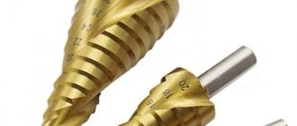
- 1x drill (diameter = 16 mm; length = 460 mm)
- 1x PID temperature controller - 12V DC version
- 1x SSR-25DA 3-32VDC / 24-380VAC / 25A solid state relay
- 1x K type thermocouple
!!! Sometimes the PID controller comes complete with a SSR and a K-type thermocouple!!!
- 1x 20A motor controller
- 1x 12V, 240W + power supply
- 1x Micanite ring heater (200W, 25mm x 30mm)
- 2x fans (80mm), 12V
- 1x 19 mm (3/4 inch) Nipple - length 18 cm
- 1x Water Tap Extension - 19mm Thread - 50mm Length, 27mm Diameter (one internal thread and one external thread)
- 1x 13mm plug
- 1x filter for installation on the faucet - diameter 13 mm
- 3x steel angle
- 1x Thrust Ball Bearing - Precisely fits onto the auger shaft.
- 2x threaded rods 10mm
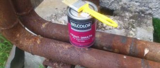
- 1x insulation
- PTFE tape
- Heat resistant tape
- 3 rocker switches (formerly "rocket"
- 1x wooden board 100cm x 10cm x 2cm
- Several screws and nuts
- 2 slots (1 for auger and 1 for crankshaft nuts)
- Threads (two colors)
Tools:
- Multi tool
- Saw
- Hammer
- Drill
Step 2: Base Plate
Take a piece of wood and cut two pieces 15 cm long. These will support the motor and extruder barrel.
Step 3: Mounting the Motor
Place the wiper motor on the motor mount and place it somewhere on the end of the base plate. See technical drawing for quotation.
Use steel angles to secure it to the base plate.
The motor has only one threaded shaft. To install the coupling on the engine, you can take a hex nut with an outer diameter of 13 mm and put it on the shaft. Once the shaft is rotating and the coupling is connected, the nut can be loosened. To avoid this, simply drill a hole between the attached nut and the motor shaft and insert a 2mm thick steel bolt. This prevents the nut from opening. See the image above.
Step 4: Attaching the Auger
Drill two holes in the other wood board so that the flanges can be attached to the left and right of the board. Drill another 1/2″ hole for the drill bit.
Both circuits require their center holes to be aligned with each other in order for the auger/coupling/shaft axis to rotate freely.
Secure the flanges with two pieces of 10mm threaded rod. The rods must be long enough to thread onto the auger to prevent kickback. 10 cm is enough. Later they can be cut to the desired size.
Step 5: Anti-Auger Kickback Protection
As the auger rotates and extracts the pellets, a lot of pressure is created. In a worst-case scenario, this could damage the auger drive inside the wiper motor. To solve this problem we need anti-kickback protection. This is simply done using a strong angle steel and a thrust ball bearing. These ball bearings can withstand a lot of force applied to them.
It works like this: the screw is pushed away due to “reverse” rotation. Due to its taper, the screw shaft is pressed against the axial ball bearing, which, in turn, is pressed against the steel angle. The coupling between the auger and the motor should always have a slight play. Therefore, no force is applied to the motor shaft.
Now position the angle steel with the rods inserted away from the barrel support so that the auger rod protrudes about 3-4 cm.
The size of the parts may vary depending on what you have access to. So an exact measurement may not help you much, but the pictures should give you an idea of how it should fit.
Step 6: Barrel and Auger
Box:
- Smooth out the ends and joints of the pipe so that the auger can rotate freely.
- Before drilling a hole in the pipe, screw it tightly onto the flange, mark the top and remove the barrel again.
- Take your multitool and cut out the marked area on the end of the tube where you want the pellets to go. Wrap this end of the tube with PTFE tape. This is necessary to prevent the pipe from turning when the augers move. Remember that the motor is very powerful and if there is some friction between the auger and the pellet, the tube will easily turn another 4-5mm, even if it has been secured with a wrench.
- Flanges and fittings are not threaded for an ideal 90° angle. Therefore, the choke/barrel can be set at an oblique angle. To solve this problem, take some washers and place them under the flange if necessary.
- Take a square piece of wood and drill a longitudinal hole for the pipe. Now drill another hole perpendicular to the “tube channel” so that the bottle fits snugly. Now simply cut the block in half for easier assembly/disassembly.
Lives:
- The auger may be too long, so you'll need to cut the bit using an angle grinder.
- The auger nozzle must reach the heater. See the images above.
Step 7: Connecting the Auger to the Motor
Take a square piece of steel 5 cm thick, which fits into the ends of the sockets (edge length is about 12 mm).
Place the bushing on the auger and secure the motor to the motor mount.
The sleeve should now fit snugly in the center.
Alternatively, you can use a candle instead of two sockets. However, this requires adjusting the distance between the motor mount and the auger/cylinder mount.
Step 8: nozzle
Nozzle diameter:
Depending on the material being cut, the diameter of the nozzle hole will vary, and finding the right size is a process of trial and error. In my experience, for ABS/PC granules with a melting point of 240-280°C, a 1.5mm hole is suitable.
Switch plate:
Take the filter fitted to the tap and cut it to 13mm in diameter if necessary. It will act as a bumper plate. These spray plates mix the melted plastic and trap dirt (which of course it shouldn't), and eventually the melting process can create small bubbles that help smooth out the plastic being pushed through the nozzle.
Take the washer, place it in the end cap and place the switch plate on top.
Step 9: Ring Heater and Temperature Sensor (Type K Thermocouple)
Drill a 2mm hole next to the thermocouple tap extension.
Strip the thermocouple wire to the desired length. It must be what you need.
Place the ring heater onto the faucet extension. It should be located at the end of the extension.
Next, take PTFE tape and wrap it around the threads of the faucet extension. This prevents molten plastic from being forced through the threads.
Secure the thermocouple with heat-resistant tape.
Then put on the attachment from the previous step.
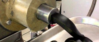
Then take a piece of aluminum tube 10 cm long and about 1 cm in diameter and place it in front of the spout using a stiff wire. This gives the filament a nice curled appearance as it cools.
Now wrap the insulation around the heater to seal the outlet.
Step 10: Cooling
The front of the injector and the engine need some cooling.
When the thread comes out of the nozzle, it is still very warm and soft. Cooling is very important so that it does not stretch too much due to the overload caused by a fall. The colder you get, the better you can check the thread diameter later.
Step 11: Electronics
Now that most of the mechanical parts are installed and ready, it's time to install the electronics.
But first take a piece of wood for the front panel, place the 3 switches, PID and motor controller potentiometer and glue them with hot glue.
Connect the power cable using the /t toggle switch to the power source (L, N and ground ports).
Connect the PID temperature controller with switches to the power source.
Connect the 12V ports of the solid state relay to the PID controller (ports 6 and 8). Connect port 1 of the solid state relay to the 220V port (port L) of the power supply. Connect port 2 of the SSR to one of the ring heater ports. The other free port of the micanite ring heater is connected to the N port of the power supply.
What does SSR actually do??
The ring heater is rated for 220V, but the PID controller only operates on 12V. Therefore, the SSR connects the 12V PID controller to the 220V heater. The PID turns the SSR on and off as needed. When it is turned on, 220 V is connected to the caliper heating element and heats up. If the relay is off, the loop resistors are not connected to 220V and are therefore disabled. The idea is to control a high power device (heater) with a low power device (PID).
Motor controller
Connect the motor controller with switch to the power source. Then connect the motor to the motor controller. Use the pinout to set the second motor speed. The pinout varies from model to model, and you'll first need to figure out which pins are for which speed setting. The two fans connect to the same motor ports on the motor controller.
How to make an extruder for a 3D printer with your own hands?
Essentially, you need to separately assemble the cold-end, then attach the hot-end to it. Fix the resulting structure on the Z-axis carriage and supply power to the resulting structure. But before that, you should write out in advance all the components that will be useful in your work.
Extruder mechanics
What do you need?
To assemble an extruder, you will need to make or buy mechanical components, electrical parts, and also make parts of the housing in which all the components of the extruder will be located. Tools you will need: sandpaper, drills, screwdrivers, soldering iron and soldering supplies.
Mechanical components
Interesting! Some sellers on AliExpress offer disassembled extruders, piece by piece. This option can also be considered.
Main mechanical components for assembly:
- main parts of the extruder frame (printed on another 3D printer, made of plywood);
- metal guides;
- gears for electric drive;
- main gear and pressure roller with spring;
- mounting screws and bolts;
- work site.
The entire mechanical part of the extruder is cold-end. The feeder is assembled like a construction set. Here we propose a general outline of the mechanics. It may vary slightly, depending on the selected drawing and manufacturing method.
Scheme for printing frame
Electrical components
Electrical components include three things: wires, a motor, and a heating element. We will tell you more about the motor power a little later. For now, let's take a look at the heating element assembly diagram.
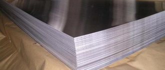
Homemade extruders often use an aluminum plate. It is not necessary to take a solid block; you can get by with a plate at least 4 mm thick. It is sold in building materials stores. Heater construction diagram:
- Connect two metal plates together, drill a hole between them for the hot-end. Place the resulting “sandwich” in a vice and secure it with a bolt.
- At the junction of the plates, make holes for: two resistors, a thermistor and a fastening bolt. Connectors for heating resistors must fit without gaps. The slightest air gap can lead to an uneven filament melting zone.
- Install all components into the plates and fasten them together with a bolt.
- Mount the heating element to the hot end. Solder the wires.
Two 5–10 Ohm resistors can be used as heating elements. Select the required resistance based on the performance of the power supply.
Important! A 100 kOhm NTS thermistor (B57560G104F) can be used to control heating. Thermistors with lower resistance should not be used. At high temperatures they give a large error.
Step-by-step instructions for assembling a 3D printer extruder
At this stage, we already have an assembled frame for the extruder with an installed roller, as well as a pressure gear. All that remains is to select a suitable motor, adjust the pressure roller and screw on the hot end with the installed heating element. Let's look at each step separately.
Engine selection
For home needs, you will need a Nema17 type stepper motor. But you can do it easier: find a working element in an old printer or scanner. This is the “weakest” engine option. For the printer, take a bipolar motor with 4 outputs.
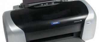
Interesting! For rods with a diameter of up to 1.75 mm, you can look for a motor from the Epson “EM-257” printer. It produces a torque on the shaft of up to 3.2 kg/cm.
If the motor does not cope, you need to install an additional gearbox. For example, from an old screwdriver. The resulting design is sufficient for rods up to 3 mm in diameter.
Adjusting the pinch roller
The clamping force can be checked experimentally when the cold-end is already assembled in the extruder. Carefully insert the rod between the roller and gear. Apply voltage to the motor. The cold-end structure itself can be carefully fixed in a vice.
If the filament does not grip or slips: the spring needs to be stretched or replaced. The thread is not pushing in, is the gear scraping against the rod? Press or bite off the spring coil. Try to find the optimal ratio of length and clamp.
Creating a hot end
To create your own hot-end you will need:
- Hot end barrel. You can make a spare part in a turning workshop. This solution will be optimal, since you will receive an all-metal hot-end, which will need to be modified to a minimum.
- Radiator. It is advisable to provide it with active cooling in the form of a small cooler. You can buy a cheap blower at a computer store.
- A heating element. The assembly is described above in the article. You can also buy a ready-made version on AliExpress.
Hot end circuit
The diagram for turning the barrel is shown in the drawing. A heating element and a radiator are attached to it. Electrical connection. A nozzle of the required diameter is screwed to the resulting hot-end.
Barrel drawing
Assembly
The entire assembly process can be divided into several stages:
- Manufacturing of cold-end mechanical parts. Assembly of all mechanical parts into a single frame.
- Selecting a suitable engine. Installing the motor in the mechanical part. Assembling the heating element.
- Pressure roller calibration.
- Hot end assembly. Connecting a heating element to it.
- Installation of hot-end to cold-end.
- Installing a nozzle of the required diameter.
The wires can be partially soldered while assembling various components, or they can be dealt with at the last moment. There is no fundamental difference.
Filabot Original
You can make plastic filament for a 3D printer, but you'll need to make your own extruder to do it. We will tell you how to do this a little later. It is also easiest to buy ready-made portable and mobile devices, such as Filabot Original. This 3D printer filament making machine can produce 1.75mm or 3mm diameter plastic filament. The equipment works with a wide variety of plastics: ABS, PLA and HIPS.
The device works with plastic granules, which allows you to keep the temperature under control. There is a filter to prevent the entry of contaminants. The universal power is sufficient for home use. Dyes are used to obtain different colors of thread. The choice of this equipment is due to its high productivity: it takes about 5 hours to produce one kilogram of yarn.
Mistakes and ways to avoid them
During assembly, you can make a number of mistakes that will later affect the print quality:
- Choosing a low-power motor. Lack of gearbox. An error in electrical design can lead to frequent extruder blockages as well as printing defects.
- Incorrect electrical calculation. Even at the development stage, you need to calculate the entire load in terms of power and resistance on paper. Otherwise, some components will simply burn out or perform poorly.
- Air gap in the heating element. Make neat holes in the aluminum plates so that the resistors fit snugly in place.
- Lack of pinch roller calibration. It is worth deciding this point in advance, otherwise you can ruin a large amount of filament.
An indirect mistake that may come back to haunt you in the future is a weak extruder frame. Once again, make the frame from the least amount of parts. Give preference to plastic over plywood. The structure must be strong. Otherwise, backlashes may appear. Print quality will noticeably drop.
Assembling the extruder is not difficult, but at some points you need to be patient. For example, in the manufacture of a hot-end barrel. It is also worth keeping in mind all the errors that may arise during the assembly of this unit.
- March 28, 2021
- 2197
About creating homemade devices
Very often, those who want to work with 3D printers begin to create filament production devices themselves in order to reduce their costs. Indeed, such devices are still not so good in their efficiency and usefulness:
- the filament may be of poor quality, insufficient or incorrect thickness, which will affect the deformation of the final product or even the impossibility of printing;
- when heated, plastic can release harmful substances that you will have to breathe in both during printing and when processing raw materials;
- recycling colored plastic will be impossible, since you will not know the composition of the plastic and the dye.
It is difficult to create high-quality plastic using DIY extruders. Therefore, it is better to buy portable equipment from trusted brands.
Production
A manual extruder for polypropylene with your own hands is one of the simplest ways to purchase such a unit. It should be noted that the assembly process is not as complicated as it might seem, and anyone can do it.
The production of extruders is a rather interesting process, directly dependent on the configuration and purpose of the unit. Manufacturing differences:
- number of working chambers;
- availability of additional systems;
- design of elements.
The only thing that remains constant is the cylindrical shape. Today it is considered the most technologically advanced, and therefore remains itself.
Alternative unit
A manual extruder for polyethylene also belongs to the general cohort of extruders, although it has a slightly different purpose. What is this unit used for? For connecting various polymer products. The welding extruder is especially good in this area, applicable to various materials. This unit greatly facilitates working with small and very small plastic products.
In this article we will look at how to make an extruder. But first, let's understand what extruder and extrusion are. An extruder is a machine for continuously processing polymer raw materials into a homogeneous melt and giving it shape by pressing through an extrusion head and a special calibrating device.
Extrusion (technological process) is a method and process for producing products from polymer materials by pressing a melt of material through a molding hole in an extruder.
In simple terms, plastic is melted in the device’s chamber and pressed under pressure through a head nozzle into a mold.
Tools and materials: -Metal pipe with a thread at the end; -Socket head; -Extension for head; -Welding machine; - angle grinder; -Vise; -File; -Perforated corner; -Two corner brackets; -Copper tube; - Fasteners; -Metal clamp; -A heating element; -Thermoregulator with sensor; -Fiberglass; -Aluminum tape; -Fitting; -Metal strip; - Angle; -Drill;
Step one: piston The extruder chamber will be made of a 20 mm metal pipe. The inner wall of the pipe must be smooth without a seam. Plastic will be placed inside the chamber, heated and squeezed out through the nozzle. A piston is needed to extrude. The master made the piston from a socket head. I selected the head according to the diameter of the tube. I installed it on an extension cord. Welded the head to the extension cord. I welded the end hole of the head.
Read also: How to remove a bearing from a hammer drill armature
A manual welding extruder is a tool for performing repairs and maintenance of products made from polypropylene, as well as related materials with a low melting point. In industry and everyday life, the unit is usually used when installing a pipeline.