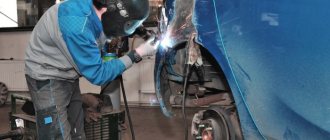
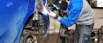
Do-it-yourself welding machine for welding small parts
Quite often in the practice of any owner, the need arises to connect metal parts. One such connection method is welding. But what to do if you don’t have a welding machine? Of course, you can buy it, but you can also make the simplest device yourself, and in almost half an hour.
Prologue
The simplest prototype of a welding machine - a lighting electric arc projector - was used back in the mid-twentieth century in film studios during the filming of films.
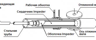
At home, it is possible to make a simple, rare homemade welding machine from a 200 W autotransformer. (An approximate diagram of an autotransformer is shown in the figure). The output voltage is regulated by rearranging the television plug in the sockets.
On the secondary winding of the transformer, you need to find two terminals at which the voltage will be about 40 V. All that remains is to connect the graphite electrodes to these terminals and the welding machine is ready! However, it must be taken into account that when using such an autotransformer for welding purposes, it is advisable to have a good knowledge of the basics of electrical safety, since galvanic isolation from the electrical network is not ensured.
The scope of application of such a homemade welding machine is quite wide: from welding metal products to hardening the working surfaces of the tool.
Examples of Voltaic Arc Applications
In the practice of radio amateurs, at times there is a need to weld or very strongly heat small parts. In such cases, there is no need to use a serious welding machine, because... To create high-temperature plasma it is not necessary to have special equipment.
Let's look at several examples of the practical application of the Voltaic Arc.
Welding filament magnetron with power buses
In this case, welding is simply necessary, although many, when faced with such a difficulty, replace the magnetron. But most often there are only two malfunctions: the filament breaks at the point (item 1) and the feed-through capacitors (item 2) fail due to breakdown.
The picture shows a magnetron from a Kenwood microwave oven, which worked after repair for more than twenty years.
DIY thermocouple repair
Of course, making a thermocouple is a completely hopeless task, but it happens that it needs to be repaired if the “ball” breaks. Typically, such thermocouples are found in multimeters that have a temperature measurement mode
Heating High Carbon Steel
If it is necessary to change the shape of the spring or make a hole, it should be taken into account that the hardened spring is too hard for drilling and too brittle for making a hole with a punch.
And in the case of hardening a steel tool (made from tool steel), it is enough to heat the working surface to a crimson color and cool it in a bath with machine oil. The figure shows a hardened screwdriver blade after machining the working edge.
How to get a Voltaic Arc?
Small welding work can be performed using a transformer with a power of 200 watts and an output voltage in the range from 30 to 50 volts. In this case, the welding current should be 10-12 Amps. There is no need to worry about the transformer overheating, since the arc burns only for a short time.
An ordinary laboratory autotransformer LATR with a current of 9 Amperes is also suitable. However, the full extent of the danger must be taken into account due to the fact that there is no galvanic isolation from the electrical network.
In order to prevent damage to the graphite roller of the LATR current collector, it is advisable to limit the input current by using a fuse. Then an accidental short circuit in the electrode circuit is no longer scary.
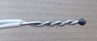
Electrodes can be any graphite rods of simple pencils (preferably soft).
The metal part of the electrical terminal block is used as a holder for the lead.
This figure shows an example of a holder using a terminal block, with one hole used to attach the handle, and the second to clamp the lead into the terminal.
In order to prevent melting of the disposable syringe (item 3) when the terminal block (item 1) is heated, fiberglass washers (item 2) are used. And for a standard connection to the cable, you can use the standard socket from the device (pos. 4).
So, the connection diagram is quite simple: one terminal of the secondary winding is connected to the holder, and the second terminal is connected to the part being welded.
There is another option for attaching the electrode holder using an electrical terminal. The second holder will be needed in case of welding metal products with the same melting point or if it is necessary to heat the metal product (hardening, changing shape).
Diagram for connecting two graphite electrodes to the secondary winding of a transformer.
To protect your eyes from corneal burns and from sparks, it will not be enough to use dark glasses due to the low density of light filters. The following device can be made: the frame of binocular glasses with the lenses removed can serve as a shield; The filter is attached using a stationery clip. Or you can use amateur radio glasses used in SMD technologies.
When welding copper with nichrome or steel, you will need flux. When a small amount of water is added to sodium tetraborate (borax) or boric acid, a paste is obtained, which is used to lubricate the welding areas.
The materials for making flux can usually be found at a hardware store. You can also use Borax insect repellent containing boric acid.
Prologue
The first time I built such a welding machine was as a child, after I visited the set of a feature film where electric arc spotlights were used for lighting.
Fortunately, we had a two hundred watt autotransformer at home, which was used to adjust the supply voltage of a tube TV.
The circuit of this autotransformer looked something like this. Switching the output voltage was carried out by rearranging the TV plug in several sockets.
So, I connected graphite electrodes between the terminals, at which there was a voltage of about 40 volts. I used a piece of exposed and developed photographic film as a filter. True, due to inexperience, then I still picked up the “bunnies”.
It should be noted that the autotransformer does not provide galvanic isolation from the electrical network, so it is recommended to use it only if you are familiar with the basics of electrical safety.
Many years have passed since then, but I have successfully used that first experience in solving a wide variety of problems, from welding wires to hardening the working parts of tools.
DIY welding transformer
The assembly of the transformer version will be slightly different from the previous one. This unit operates on alternating current, but for welding with direct current you need to assemble a simple attachment for it.
To work, you will need transformer iron for the core, as well as several tens of meters of thick wire or thick copper busbar. All this can be found at the metal collection point. The core is best made U-shaped, toroidal or round. Many also take the stator from an old electric motor.
The assembly instructions for the U-shaped core look like this:
- Take transformer iron with a cross-section from 30 to 55 cm2. If the figure is higher, the device will be too heavy. And if the cross section is less than 30, the device will not be able to work correctly.
- Take a copper winding wire with a cross-section of about 5 mm 2, equipped with heat-resistant fiberglass or cotton insulation. Insulation is important because during operation the winding can heat up to 100 degrees or more. The winding wire has a square or rectangular cross-section. However, such an option is difficult to find. An ordinary one with a similar cross-section will do, but you will only need to remove the insulation from it, wrap it in fiberglass and thoroughly soak it with electrical varnish, and then dry it. The primary winding has 200 turns.
- The secondary winding will require about 50 turns. There is no need to cut the wire. Connect the primary winding to the network, and on the secondary wires find a place where the voltage is about 60 V. To find such a point, unwind or wind additional turns. The wire can be aluminum, but the cross-section must be 1.7 times larger than for the primary winding.
- Install the finished transformer into the housing.
- To bring out the secondary winding, copper terminals are required. Take a tube with a diameter of 10 mm and a length of about 4 cm. Rivet its end and drill a hole with a diameter of 10 mm, and insert the end of the wire, previously cleared of insulation, into the other end. Next, crimp it with light hammer blows. To strengthen the contact of the wire with the terminal tube, apply notches to it with a core. Screw homemade terminals to the body with nuts and bolts. It is best to use copper parts. When winding the secondary winding, it is advisable to make taps every 5-10 turns, they will allow you to change the voltage on the electrode in steps;
- To make an electrical holder, take a pipe with a diameter of about 20 mm and a length of about 20 cm. At the ends, about 4 cm from the end part, cut out recesses to half the diameter. Insert the electrode into the recess and press it with a spring based on a welded bush of steel wire with a diameter of 5 mm. Attach the same wire that was used for the secondary winding to the second terminal using a nut and screw. Place a rubber tube with a suitable inner diameter onto the holder.
It is best to connect the finished device to the network using wires with a cross-section of 1.5 cm2 or more, as well as a switch. The current in the primary winding usually does not exceed 25 A, and in the secondary winding it fluctuates between 6-120 A. When working with electrodes with a diameter of 3 mm, stop every 10-15 to allow the transformer to cool down . If the electrodes are thinner, this is not necessary. More frequent breaks are needed if you are working in cutting mode.
Do-it-yourself mini-welding
To assemble a miniature welding machine yourself, you will only need a few hours and the following materials:
- graphite rod from an old battery;
- side cutters or pliers;
- knife;
- dry rag;
- sandpaper;
- gloves;
- 20 cm of wire with a diameter of 5 mm made of aluminum or copper;
- 6 cm of PEV 0.5 copper wire;
- insulating tape;
- stranded wire;
- any metal clamp;
- a transformer from a microwave power supply with a rectifier, or an old TV or receiver.
Production of welding equipment: instructions.
According to experts, a three-phase step-down transformer should be chosen as the basis of the equipment.
The secondary windings are removed from the coil, the primary wires and core are left in their original form, the middle wire is wrapped in the same material with 8-10 turns at the output.
To independently produce welding equipment, you need a 25 m cable, a copper pipe 10-12 mm in diameter, a metal disc and a grinder.
It is necessary to ensure that both coils located at the edges are filled by carefully winding the secondary winding using a multi-core three-phase power cable. The flexible wire winds without the need to disassemble the equipment.
The parameters of the wires in the cable are 6-8 mm in diameter. One of them should be thinner, but with good insulation and resistant to current power. For the production of the device 25 m of cable. If necessary, it can be replaced with wires with a smaller cross-section.
It is more efficient to do this work together: one person will do the pulling of the wire, the second will do the laying of the turns. To make a terminal, you need a copper pipe 30-40 mm long and 10-12 mm in diameter.
One part of it is separated, which forms a plate in which a hole up to 10 mm in diameter is made; pre-stripped wires are inserted into the other part. Experts advise crimping the wires with a hammer.
Contact will improve if several notches are made on the outside of the pipe.
New fasteners with M10 threads replace the existing screws and nuts at the top of the transformer, to which the terminals from the secondary winding are then attached.
It is necessary to make 11 holes (no more than 6 mm in diameter) in the textolite board for screws with nuts and washers; and firmly attach it to the surface of the transformer. These components will provide the output of the primary winding.
The electric holder is made from ¾ pipe 25 cm in length. It is necessary to make recesses in the corners, and weld a small piece of metal wire to the holder.
A hole is made on the reverse side and a piece of cable is connected, as with the secondary winding. Then you need to insulate the pipe with a rubber hose.
We make welding machines with our own hands
Welding work at home has long become commonplace. Availability of equipment and consumables, the opportunity to inexpensively attend welding courses, various training manuals for acquiring independent skills. All these factors make it possible to save on the labor costs of a professional welder and increase the efficiency of work.
However, if you carefully study the welding machine market, unpleasant aspects become clear:
- High-quality welders have a high cost; it is more profitable to hire a specialist several times (unless, of course, you do this work constantly).
- Affordable units have a number of disadvantages: low reliability, poor seam quality, dependence on the supply voltage and type of consumables.
Hence the conclusion: if you need high quality equipment at an affordable price, you will have to make a welding machine from available materials with your own hands.
How resistance welding works
This is a thermomechanical type of welding. Before starting work, the welded parts are arranged in the desired position. Next, each part of them is fixed between hardware electrodes, under their action the parts are compressed.
The current passing through the electrodes heats the parts, and an alloy is formed at this point. It is the connecting element of two parts. Devices of this type in production have high productivity. They are capable of making 600 weld points in a minute.
But in order for the surfaces to become hot and begin to melt, an electric current of enormous strength is supplied to them. Such an impulse leads to almost instantaneous melting of metals. Its duration depends on the type of metals being fused. Typically the time range is 0.01-0.1 seconds.
In this case, the molten metal surfaces form a welding drop between themselves, which must harden. To do this, the welded parts are kept compressed for some time. The molten drop at this moment forms a kind of crystal lattice.
Pressure plays an important role in this process. It prevents the molten drop from spreading over the area of the parts, thus being held together at one point. The compression force is gradually reduced, then the weld is better set. This work requires clean surfaces of the parts.
Therefore, before work, the intended location of the weld is treated with a special solution. This removes corrosion elements and other oxide films. The result is a high quality seam.
Before considering options for homemade welders, let’s look at the principle of their operation.
The operation of any unit is based on Ohm's law. At constant power, there is an inverse relationship between current and voltage. For normal operation, a current of 60–150 A is required. Only in this case will the metal in the welding zone melt. Let's imagine a welding machine that operates directly with a voltage of 220 volts. To achieve the required current, a power of 15–30 kW will be required. Firstly, for this it will be necessary to lay a separate power supply line: most inputs into residential premises are limited by technical conditions at the level of 5–10 kW. In addition, such a current will require wiring with a cross-section of at least 30 mm². You will have to cook in compliance with protective measures when working in electrical installations up to 1000 volts: rubber boots, gloves, work area fencing, etc.
Of course, it is impossible to ensure such conditions in reality.
Therefore, any welding machine converts the voltage (downward): at the output we obtain the desired current while maintaining reasonable power.
The optimal voltage value is 60 volts. With a welding current of 100 A, this is a completely acceptable 6 kW of power. How to convert voltage?
Basic methods
The general development of welding and electronic technologies has led to the emergence of new methods for welding valuable jewelry. Based on the process technology used, currently existing welding machines for jewelry can be divided into three types:
- spot electric arc welding using a non-consumable electrode;
- electric contact welding;
- welding using laser.
In addition to the listed technologies, there is also a diffusion connection. This method should be considered separately from the above, since it is carried out by rather primitive means and does not require the use of complex technical devices.
There are four main types of welding machines
- Transformer. The device operates on alternating current. The main unit is no different from a conventional power supply: the input is 220 volts, the output is the required 60 volts. Due to the possibility of mechanical movement of the secondary winding along the core, the value of the operating current changes.
Advantages: simplicity and low cost of design, maintainability. Disadvantages: large size and weight, alternating current leads to unstable formation of the weld, highly qualified specialist is required for work. - Rectifier. Essentially, this is the same transformer, only with a diode (thyristor) rectifier in the secondary winding circuit.
After converting the voltage through a transformer (with a traditional mechanical current regulator), the secondary AC voltage is rectified in one of the following ways. In primitive (inexpensive) designs, a diode bridge is used. More advanced circuits operate on a thyristor circuit, with the ability to adjust parameters. Advantages: stable welding parameters, the ability to work with various metals, no highly qualified craftsman required. Disadvantages: higher cost, difficulty in repair and maintenance. Some craftsmen convert a simple transformer welder into DC apparatus. To do this, you just need to assemble a powerful rectifier and connect it to the output of the secondary winding. This will require powerful diodes (assembling a bridge) and radiators to dissipate heat.
A common drawback of the considered schemes is the dependence of the output parameters on the quality of the electrical network. If there are voltage sags (this is normal during welding), the characteristics of the output voltage and current change. As a result, the quality of the weld seam suffers. Therefore, manual adjustment of the current strength (by moving the windings) is mandatory.
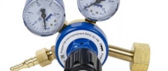
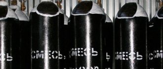
- Semi-automatic This is an advanced version of the rectifier, with a device for mechanically feeding welding wire into the work area. Welding is carried out in an inert gas environment; a gas cylinder is required to complete the work. Advantages: high-quality weld, no need for special training of the craftsman. Disadvantages: additional equipment required (gas cylinder), high cost.
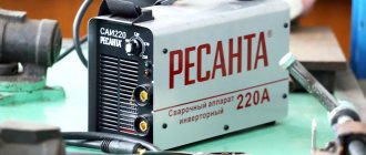
- Inverter. Today, it is the most common welder among amateurs. An inverter power supply with PWM control is used as a voltage converter. This technology has now become accessible, which has a positive effect on the cost. Advantages: even a novice welder can operate the device, compact size, light weight. Disadvantages: not very high reliability, difficult to repair.
Any of the listed devices can be assembled independently. Let's review manufacturing technologies by model:
Diffusion welding
The essence of the diffusion process comes down to the following. The contact surfaces of the jewelry are ground and thoroughly cleaned, after which they are clamped with great force between steel plates and heated “red hot” (to be precise, to 70 - 80% of the melting point) in a muffle furnace or forge.
When the workpieces are kept in this state for a certain time, mutual diffusion of their atoms occurs at the point of contact of the parts, which leads to the creation of a strong permanent connection.
Source: svaring.com
Transformers (with or without rectifier)
The heart of a transformer is the core. It is assembled from transformer steel plates, which are quite problematic to make by hand. By hook or by crook, the source material is extracted at factories, construction teams, and scrap metal collection points. The resulting structure (usually in the form of a rectangle) must have a cross-section of no less than 55 cm². This is a rather heavy structure, especially after laying the windings.
During assembly, it is imperative to provide an adjusting screw, with which you can move the secondary winding relative to the stationary primary.
In order not to go into the complexity of calculating the cross-section of wires, we will take typical parameters:
Based on this, the cross-section of the primary wire should be at least 5 mm²; if you do it with a margin, you can take a wire of 6–7 mm². The insulation must be heat-resistant and made from a material that does not support combustion.
VRTP -> Welding from 12 volts.
- Divide the total number of turns of each winding into two equal halves to place them on both core bars.
- If you assemble a core from individual plates, you will need to fix them with ties or in a simple cage. The plates should not be isolated from each other.
- For the coils, a frame is made of thick electrical cardboard. The internal size must correspond to the cross-section of the core and must allow the coil to be moved up or down.
- The windings are wound by laying the turns close to each other. If necessary, make several rows of laid wire.
- If the primary winding is designed with taps, then a loop is made on the required number of turns and brought out without cutting it.
- The primary winding is placed on the lower part of the core, the secondary winding is attached to the top.
- To change the current strength for welding metals or when working with parts that differ in thickness, a simple regulator is provided. It will move the secondary winding coils up and down.
- The operating principle of such a regulator is based on changing the air gap between the windings. As a result, the parameters of the magnetic field change, which leads to an increase or decrease in the current strength in the secondary winding.
- The regulator is a threaded screw, which, when tightened, raises the coils. To do this, these elements are connected to each other.
Inverter (pulse power supply for welding)
A homemade inverter welding machine cannot be made simply “on the knee”. This will require a modern element base and experience in repairing and creating electronic devices. However, the scheme is not as scary as it is made out to be. There are a great many similar devices made, and they all work no worse than their factory counterparts. In addition, to create a pulse welding machine with your own hands, it is not necessary to purchase dozens of expensive radio components and ready-made components. Most of them, especially high-frequency elements for the power supply, can be borrowed from old TVs or power supplies from a computer. The cost is close to zero.
The inverter in question has the following characteristics:
- Load current on the electrodes: up to 100 A.
- Power consumption from a 220 volt network is no more than 3.5 kW (current about 15 A).
- Used electrodes up to 2.5 mm.
The illustration shows a finished circuit, which has been repeatedly tested by many home craftsmen.
Structurally, the inverter consists of three elements:
- Power supply for the converter and control circuit. Made on an accessible element base, using an optocoupler from an old computer power supply. When making a transformer yourself, the cost is almost zero: the parts are cheap. The values and names of radioelements are shown in the illustration.
- Capacitor charge delay unit (for starting arc). Made on the basis of KT972 transistors (absolutely not a shortage). Of course, transistors are installed on radiators. For switching, an ordinary automotive relay with a current load on the contacts of up to 40 A is sufficient. For manual control, ordinary circuit breakers (packets) of 25 A are installed. Output 300 volts - idle. At load the voltage is 50 volts.
- The current transformer is the most critical component. During assembly, special attention should be paid to the accuracy of the inductors. Some adjustment can be made using a variable resistor (highlighted in red in the diagram). However, if the parameters are not consistent, the required arc power will not be achieved. PWM is implemented on the US3845 chip (one of the few parts that will have to be purchased). Power transistors are the same KT972 (973). Some elements in the diagram are imported, but they can easily be replaced with available domestic ones by searching for analogues on the datasheet website. The high-frequency unit is made from parts of a line transformer from a TV.
Working wires no longer than 2 meters are connected to the output of the welding inverter. The cross-section is at least 10 squares. When working with electrodes up to 2.5 mm, the current drop is minimal, the seam is smooth and even. The arc is continuous, no worse than the factory equivalent.
If there is active cooling (fans from the same computer power supply), the design can be compactly packed into a small case. Considering high-frequency converters, it is better to use metal.
The more complex the homemade welding machine, the greater the savings. It is simple transformers that are more expensive due to the use of expensive copper in the windings or transformer iron. Switching power supplies, especially if you have old parts from standard electrical appliances in stock, are practically free.
Where to start assembling an inverter apparatus?
To assemble the inverter, you need to select a circuit that will provide the necessary operating parameters of the device. It is recommended to use Soviet-made parts. This is especially true for diodes, capacitors, transistors, resistors, chokes, thyristors and finished transformers. The equipment assembled on these parts does not require complex adjustments. All parts are very compactly located on the board. To make the device yourself, you can select the following parameters:
- The welding machine must work with electrodes with a diameter of up to 4-5 mm.
- The operating current is no more than 250 A.
- Power source - household network voltage 220 V.
- Adjustable welding current within 30-220 A.
The welding machine consists of several blocks: power supply, rectifier and inverter. You can start making an inverter-type welding machine with your own hands by winding a transformer in this order:
To assemble the inventory, you will need a ferrite core.
- You need to take a ferrite core Ш8х8. You can use W7x7.
- Primary winding No. 1 consists of 100 turns, wound with PEV 0.3 wire.
- The secondary winding No. 2 is wound with a wire with a cross-section of 1 mm. The number of turns is 15.
- Winding No. 3 - 15 turns of PEV wire 0.2 mm.
- Windings No. 4 and No. 5 consist of 20 turns of wire with a cross section of 0.35 mm.
- To cool the transformer, you can use a 220 V, 0.13 A fan. These parameters correspond to a fan from a Pentium 4 computer.
In order for transistor switches to operate smoothly, they need to be supplied with voltage after the rectifier and smoothing capacitors. The rectifier unit is assembled according to a simple circuit board. All components of the welding machine are fixed in the housing. It’s good if the craftsman has a suitable housing for a radio device, then he won’t have to make it from scrap materials.
Rectifier block assembly diagram.
An LED indicator is placed on the front side of the case, which by its glow notifies that the device is connected to the network. You can also install an additional switch of any type and a protective fuse. The fuse can be installed on the rear wall, as well as in the housing itself. It depends on its design and dimensions. A variable resistance, with the help of which the operating current will be adjusted, is also located on the front side of the housing.
If the electrical circuits are assembled correctly, everything is checked using a tester or other device, you can test the device.
Advantages
It is not for nothing that laser welding of jewelry has become widespread among other methods of joining metal. This was facilitated by the following number of advantages:
- The joint seam is almost invisible, therefore, the product can create the appearance of a solid cast piece;
- Work can be carried out even with the thinnest delicate products, which is not always possible with other types of welding;
- Repairing and creating new products is not difficult if you have experience;
- The equipment has a fairly large range of parameter adjustments, which makes it possible to easily select the desired operating mode;
- You can work with precious metals without unnecessary problems when joining, as happens with other welding methods for difficult-to-weld metals;
- The welding speed is quite high;
- The productivity of the process significantly exceeds alternative methods.
Flaws
This technique also has some disadvantages that do not allow it to be used in all jewelry workshops;
- The cost of a laser machine is quite high, so not every master can afford it;
- Working with the technology requires experience, since it has some specifics and requires taking into account a lot of nuances;
- Work is carried out only with metals, while other types of materials are not suitable for this.
Technology
Welding jewelry made of brass at home, as well as other types of metal using a laser, has almost the same operating principle. Regardless of which installations are used for this, the rules for carrying out the process are the same almost everywhere. This requires strict adherence to technology, which involves both preparation and direct temperature treatment.
The metal surface should be cleaned of dirt, grease films and other unnecessary things and deposits. This can ruin the metal joint, since everything in this area should be as clean as possible. Almost all connections are made end-to-end, especially when it comes to repairs. Here one part of the part is connected to another, since the spectrum of laser action is very narrow.
The joining process can be with or without solder. Most often, the workpiece is held in the hands and brought at the connection point to the laser itself.
The installation is configured to the desired mode and turned on. In just a few seconds of exposure to the welding site, the metal begins to soften and melt. If solder is used, it first melts and envelops the joint.
The thinner the part, the less exposure time it requires to weld.”
At the very beginning, the seam may become rough and the joint will be noticeable. You can correct the position using the same laser, since immediately after joining you can smooth out the joints so that the metal turns into a flat surface.
Post-processing is not required very often. Specialists who have sufficient experience can repair jewelry that does not require further modification. Otherwise, you need to remove a small layer with sandpaper, so that the product will look the same as a new decoration.
Application area
Laser jewelry welding, as the name suggests, is used in the jewelry industry. It is mainly used for repairing and creating new products. From time to time, jewelry may break due to careless wearing, accidental impacts, falls and other cases. Chains break, pendants break at the junction, and rings periodically burst. To fix them, you need special equipment. Soldering technology is simpler and more accessible, but it leaves more marks and requires additional processing after connection. It also requires the use of solder, whereas welding provides everything you need more efficiently and reliably, after which no solder admixture is added to the metal.
Jewelry manufacturing also requires the use of lasers, as they can create bonds that are virtually undetectable. New jewelry will look almost seamless if you choose the right modes. It is also worth noting the simplified work with precious metals, where the complexity of welding certain metals is reduced to a minimum.