Damage to the body may be caused by extensive corrosion or may be the result of a severe accident. In this case, there are two ways to repair a car: replacing the body and overcooking its damaged elements. The second option requires the use of special equipment. This article discusses the tools that can be used to weld a car body, and the technologies for carrying out this work.
Welding of explosive containers
Popular message! The topic is intended as a forum quotation book on safety measures when welding containers containing flammable liquids and gases. The goal is to show exactly the amount of advice on the subject in order to give more weight and significance to the correct methods. Therefore, the advice will be repeated, and the more the better.
Actually, in order not to get a large and effective “BA-BAH”, it needs to be prevented:
I agree with this opinion, but I would like to add something. An argon cylinder in the Moscow region costs about 1000 rubles, it contains about 7000 liters of gas, i.e. filling a 500 liter tank with argon will cost about 72 rubles. Is this really such a big price to pay for quality and safety?
I was boiling the tank, washed it for two days before, it boomed so much that there was a hole at the welding site, guys, it’s scary, fill it with argon!
Further on the same topic. Pay attention to the nickname: https://websvarka.ru/. 4329#entry64329
It is also better not to conduct experiments with chemistry. The composition is not always fully and truthfully described on the packaging. It may happen that the composition will react with the same aluminum and it is unknown what solid and gaseous products you will get at the output. All this can add to the enchantment of the explosion. For example, aluminum oxides can raise the explosion temperature to enormous values. And the concussion will be complemented by extensive burns. But shell shock is an unpleasant thing and will haunt you for the rest of your life if you remain alive.
I'm tired of giving links. Click the arrow in the quote header on the right and you will be taken to the quoted message.
Motor, reduce the flow to approximately 2 l/min, but do not stop. The end of the supply hose to the lowest point of the tank.
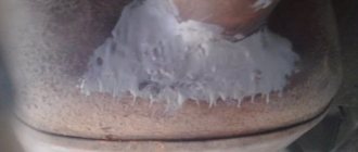
Sniffing with your nose, as if soda is coming out of the crack into your nose, it means everything is in order, it is already full of CO2, it seems to be filling up, because it is heavier than air. If necessary, you can widen the crack to make it easier to fill.
and here’s what’s inside right after welding (those same vapors in a carbon dioxide environment) Thank you Next time, I’ll probably first think about whether to take such a job or not)
I brewed my first tank in 1998. It was a tank at an oil depot with a height of 3.5 m and a diameter of 5 m. It took a month to prepare the tank for welding. The soaps steamed again, the soaps steamed again. Kaerkanskaya oil depot Talnakhskaya Dudinsky port. But I still take the tank for welding and adrenaline. I always boil the tank with water if possible. Steaming and CO. I prepare for welding myself for a fee. (vast 500 rubles). So TB and TB and fear. As soon as the fear subsides, everything is over. There are a lot of deaths due to stupidity by young people and professionals with decades of experience.
I cooked this Frankenstein. And this is not the worst tank on our collective farm. They tried to cover the crack with cold welding. Even after cleaning with a grinder during welding, there is a smell from it. The tank was filled with water + carbon dioxide was added.
Source
Welding a fuel tanker barrel without steaming
This is how my experience shows that rednecks don’t want to pay real money for such work. Therefore, let them do whatever they want with this tank, scrape, wash, steam, as long as it doesn’t smell. And before welding, I’ll make sure to put a hose from a powerful compressor into the welding zone.
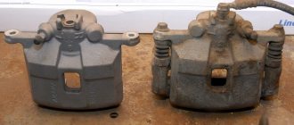
There is a fuel tanker on an AM Ural chassis, you need to weld an aluminum barrel, there are two cracks of 10 cm each. One is located on the edge at the bottom, the second at the very top, right there. There is a large volume of water (from the hydrant) and that’s all. How to protect yourself when welding? I suggest rinsing water, then leave 200 liters of water in it, pour in 10 liters of washing concentrate, foam the entire volume with carbon dioxide, then cook. What do you recommend to the forum gurus? Like the one in the photo
My advice is not to think too much, but to take it and cook it.
I cooked a diesel fuel barrel from the inside, almost blindly (I didn’t know where exactly it was leaking). It’s an iron barrel, I don’t know if there’s a big difference. I heated the intended place with a cutter (I was looking for a crack) then cooked it. I cooked it with ordinary ANO-21, there’s nothing better I didn’t have it on hand. I brewed it on the first try))). My advice is not to think too much, but to take it and cook it.
When paying for such life-threatening work, you can dance from the cost of possible losses for the owner of the tank. For example, if they don’t weld the tank, buy a new one for 100 thousand (notional price). Charge them for the work WITHOUT CONSUMABLES at least 30% of 100 thousand. Or option No. 2 - you come up with a price for the work “so that the number itself makes you scared,” and then you multiply it by two and in the bidding process you give in a little. If the customer does not agree, let them cover up this hole with snot or buy a new piece of hardware.
Source
Cost of steaming in a car repair shop
If you weld a gas tank in a service workshop, then such a service can cost approximately 1,500 rubles . It all depends on the volume and degree of damage to the tank. This amount includes:
A torn tank containing gasoline vapors
Both metal and plastic tanks can be repaired. The most important thing is to follow safety precautions and begin repairs only after getting rid of gasoline vapors , otherwise the tank may explode!
How to steam a tank correctly
If you decide not to buy a new tank, but to repair the old one, you should not be afraid of gasoline vapors. Yes, they are dangerous, but you can get rid of them quickly and effectively.
The first thing to do is remove the gas tank and inspect it for damage. If the iron tank is repairable, then you can begin to displace gasoline vapors. To do this, you will need hot water and “fairy” (or another highly foaming detergent).
Instructions for steaming the fuel tank and containers
Pour boiling water after adding 50 ml of “fairy” detergent to the tank. It will produce enough foam to clean the container. The tank must be filled to its entire volume with as hot water as possible (taking into account where the damage is located). Then you should wait 2-3 hours.
After several hours, you can drain the water and start drying. A construction hair dryer is best suited for this, but if you don’t have one, then you can get by with an ordinary household hair dryer. However, its effectiveness will be several times lower. The hairdryer should be placed in the neck and left to dry. It is advisable to ensure that the tank dries completely.
Steaming tanks like this gives good results for several reasons:
After drying, there should be no gasoline vapor left and you can begin the welding process using a semi-automatic machine (as with regular body repairs). The optimal wire thickness for this is 0.8 mm.
Other ways to evaporate a gas tank
Displacement of gasoline vapors by a steam generator
In addition to the described method, there are several more effective ways to remove gasoline vapors from a gas tank. Let's briefly look at each method.
Using a steam generator
Long-term steam treatment gives an excellent effect, but this requires specialized equipment (steam generators). At home, there is no place to get enough steam, so you will have to use other methods to evaporate the gas tank.
Ammonia
Ammonia works well to clean both diesel fuel and gasoline. For 100 liters of water poured into the tank, you need to add 40 ml of ammonia and heat the tank (the water in it) until the water boils.
Carbon dioxide
In order to displace oxygen from the tank, you will need a cylinder of carbon dioxide. Only after pouring carbon dioxide and displacing the vapors can cracks or holes be welded.
Using exhaust gases to get rid of gasoline vapors
Traffic fumes
The simplest and most proven method is to connect the tank to the exhaust pipe (preferably of a truck). Before welding, the tank must be kept in this position for 1-2 hours so that it does not explode during repairs.
Water
If the gas tank is punctured, it can be welded up fairly quickly. You need to drain the gasoline, remove the tank and fill it to the top with water. The main task is to start repairing the damage only when the tank is full and gasoline vapors have been almost completely displaced.
It would be better to place a heater in the neck of the tank and boil water to boil off the gasoline from the walls of the tank.
How can you brew a fuel tank without evaporating the vapors?
Source
Gas tank repair
The BOSCH-Service company carries out professional repairs of fuel tanks.
No matter how strong this container is, over time it can crack - and even if its thickness is insignificant, losses of gasoline or diesel will be inevitable. As soon as the driver finds out about this defect, the first thing he should do is contact a car service center for repairs. Before doing this, you can only try to repair the damage if it is large and caught you on the road far from the workshops.
Symptoms of damage:
- Fuel consumption has increased.
- Engine performance has deteriorated.
- At low speeds, interruptions in engine operation occur.
- When the car moves, jerks occur.
- There was an unpleasant smell in the cabin.
If suspicion arises, the car owner can always inspect the tank himself. In addition to the breakdown of the container itself, there may be other defects in the system that lead to a leak. Let's consider all the main factors.
Several possible causes of failure:
- Long-term use of low-quality fuel.
- Mechanical damage received during repairs, installation of other parts or due to an accident.
- Debris getting into the tank.
- Depressurization of the fuel system.
- Damage or wear of seals.
- Temperature changes that lead to the formation of condensation.
- Corrosion of the gas tank if it is made of metal.
Now let's figure out how to repair the fuel tank. Repair methods and its stages depend on the material of the product and the chosen technology.
Universal methods using patches
One of the most common repair methods is using “cold welding”. It can be called folk, and the validity period leaves much to be desired. Therefore, it is only suitable as a temporary solution.
Causes of damage to the integrity of the gas tank
To store fuel reserves in cars, a tank of complex geometric configuration is used, hidden in a niche under the rear seats. In some cars (for example, Zhiguli cars with rear-wheel drive), the container is located inside the trunk behind the wing.
The tank located under the bottom can be damaged if you move carelessly on a dirt road; steel tanks are susceptible to corrosion (both outside and inside).
An additional reason for deformation and cracks in tanks is a malfunction of the ventilation system.
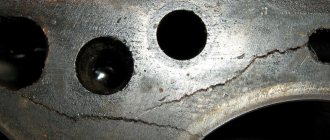
Corrosion
Water enters the tank along with gasoline or diesel fuel and settles at the bottom, destroying the metal walls. The outer part of the container under the bottom is exposed to road reagents and dirt, which leads to damage to the protective coating and the appearance of pockets of corrosion. If the tank is made of chemically inert plastic, then the surfaces are not damaged by water and salt solutions.
Corrosion occurs due to water entering the tank along with fuel.
Mechanical damage
When driving on uneven roads, the tank may be damaged by stones or tree branches. Dents with microcracks form on metal containers, through which fuel begins to flow. Plastic structures can crack if hit hard or tear off on a sharp rock edge.
Faulty power system
Fuel is taken from the tank by a mechanical or electric pump (depending on the year of manufacture of the machine), the pressure drop inside the tank is compensated through the ventilation duct.
When the tube becomes clogged, the pressure inside the container drops, and the walls are deformed under the influence of the atmosphere.
When the filling neck is unlocked or after the engine is stopped, the tank returns to its original configuration; with successive cyclic deformations, fatigue cracks appear on the walls.
Main oil tank
Tank body; 2 - guide cylinder; 3 — fitting for connecting the drainage pipeline; 4 and 8 — brackets for mounting the oil tank; 5 — pipe for supplying heated liquid; 6 - bypass valve; 7 — flange for connecting the pipeline for draining oil from the radiator; 9 — heated liquid outlet pipe; 10 - ball; 11 - spring; 12 — rod; 13, 20 — oil intake pipes for the MZN-2 pump; 14 — filter housing; 15 — oil intake filter; 16 — protective casing; 17 — flange for connecting the oil supply pipeline from the additional oil tank; 18 — casing; 19 - coil; 21 - drain valve.
Not all the oil filled into the oil tanks is involved in the work, but only that which is in the main tank. As oil is consumed, the oil from the additional tank enters the main tank through a pipeline connected to flange 17.
In the upper part of the tank, a fitting 3 is welded to connect the drainage route and a bypass valve 6 is installed to bypass the oil pumped out from the engine to the main oil tank, bypassing the oil radiators.
The valve consists of a ball 10, a spring 11 and a rod 12. It is adjusted to an opening pressure of 4.3-5 kgf/cm2.
At low temperatures, when the oil is not yet sufficiently warmed up, the resistance of oil radiators increases. In this case, the valve is activated and the oil, bypassing the radiators, is drained into the tank. A drain valve 21 is installed at the bottom of the tank.
The additional oil tank is installed in the aft part of the power compartment on the starboard side. It is welded from extruded aluminum sheets. On the front wall of the refill tank, flanges 8 (Fig. 47) are welded for connecting the drain tube from the main tank to the refill tank and flange 7 for connecting the drain tube from the refill tank to the engine. On the top sheet of the tank there is a filling neck 4, which is closed by a plug 5 with a rubber sealing gasket 6.
To prevent oil from pouring from the main tank into the secondary tank when the machine is moving uphill, a valve is installed in the lower part of the additional tank, which consists of a body 12 welded into the tank and a ball 11. Oil is poured from the additional tank into the main tank through a pipeline that is connected to the sleeve 10.
The external oil tank is mounted on the left fender above the outlet pipe. The tank is not included in the general lubrication system. Its volume is ~ 42 l, and its filling capacity is ~ 35 l. The tank is welded from extruded aluminum sheets. The outer surface of the tank is painted. The oil in the tank is heated from the exhaust pipe of the release .
Flange 4 (Fig. 48) of the filling neck with a ring that limits the amount of oil to be filled is welded on the top sheet of the tank. The filling neck is closed with a plug 5 with a sealing gasket 6. A flange 7 is welded to the tank wall, in which a drain valve 11 is installed, closed with a plug 9.
B) Engine oil pump. Gear type engine oil pump. It has three pairs of gears, forming one pumping section and two pumping sections. All sections are located in a common building.
The injection section supplies oil from the tank through the MAF filter and pipeline to the engine.
Refill oil tank:
1 — tank body; 2, 3 and 9 — tank mounting feet; 4 — filling neck; 5— plug; 6 — gasket; 7 — flange for connecting the engine drain pipe; 8 — flange for connecting the drain pipe of the main oil tank; 10— bushing; 11 - ball; 12 — valve body: 13 — bracket for mounting the breather of the transmission hydraulic system.
External oil tank:
1 — tank body; 2 — handle for transportation; 3 - partition; 4 — neck flange; 5 - plug; 6 - gasket; 7 — drain valve flange; 8 - gasket; 9 - plug; 10 - ring; 11 - valve; 12 - spring.
The main parts of the pump: housing 1, cover 6, driving 12 and driven 11 gears of the discharge section, driving 7 and driven 8 gears of the pumping sections, three drive gears 3, pressure reducing valve 14 and casing 2.
Oil pump:
Frame; 2 - casing; 3 - drive gear; 4 - retaining ring; 5 — hairpin; 6 - cover; 7 and 8 — gears of pumping sections; 9 — fitting; 10 - cap; 11 and 12—gears; 13 — clamp; 14 - pressure reducing valve; 15 — valve seat; 16 — plate: 17 — spring; 18 - bolt; 19 - plate lock.
The oil pump is installed in the lower crankcase and is centered in the bore of the crankcase flange by a cylindrical housing belt. The oil pump is driven into rotation by a spring roller, which is driven by the engine crankshaft and fits into the splines of the drive gear 12 of the injection section.
Reducing valve 14 is designed to maintain the pressure at the oil inlet to the engine crankshaft within the range of 5-10 kgf/cm2.
B) MAF oil filter. The oil filter is designed to clean the oil supplied to the rubbing parts of the engine. It is mounted vertically near the engine supercharger on a bracket welded to the power compartment bulkhead.
The filter consists of a housing 4, a cover 2, three filter sections 5, 6 and 7, a hollow rod 9, a reducing valve 8 and a shut-off valve 12.
Housing 4 is a glass cast from an aluminum alloy, in which bosses are made with machined holes and fittings screwed into them. The oil line from the pressure section of the oil pump is connected to fitting 13, and the oil lines that drain oil from the filter to the central oil supply cover and the engine supercharger are connected to fitting 14. A shut-off valve is installed in fitting 14.
The valve consists of a ball 17, a spring 16 and a cap 15. A plug 11 with an internal thread is pressed into the central hole of the glass, into which a hollow rod 9 is screwed with a centering sleeve welded to it on one side, which is bolted to the bottom of the glass. On the other side, the rod has an internal thread into which a coupling bolt 1 with a knob is screwed, pressing the cover to the filter housing. The joint between the filter housing and the lid is sealed with a rubber ring 3.
Springs and a cup are installed in the inner bore of the cover, which are kept from falling out by a locking ring. A spring through the cup tightly presses the bushings of the filter sections to each other and the inner section to the treated area of the housing.
Filter sections 5, 6 and 7 are corrugated brass glasses with a calibrated brass tape wound on them, which has a special profile that forms conical slots 0.04-0.09 mm wide. Double bottoms are soldered to the corrugated glasses, to the central part of which are soldered bushings with holes for draining purified oil from the cavities of the filter sections into the cavity of the rod.
Oil from the pump to the engine crankshaft, bypassing the filter sections of the filter (if they are clogged), is bypassed through valve 8. The valve spring is adjusted to a pressure drop in the filter of 4.7-5.8 kgf/cm2.
MAF oil filter:
Pinch bolt; 2 – cover; 3 – rubber ring; 4 – body; 5 – slot section (first); 6 — slot section (second); 7 — slot section (third); 8 – pressure reducing valve; 9 – rod; 10 – emphasis; 11 – blind rod nut; 12 – shut-off valve; 13 and 14 – fittings; 15 – cap; 16 – spring; 17 – ball; 18 – centering sleeve.
Oil filter operation. Oil from the pressure section of the oil pump is supplied through the inlet fitting to the filter housing and fills the internal volume around the filter sections. Then the oil under pressure passes through the cracks of the filter sections, cleared of mechanical impurities, and along the corrugated surfaces of the glasses enters the cavities formed by the double bottoms of the sections, and from them into the cavity of the rod.
After passing the oval holes in the rod, the holes in the filter housing and the shut-off valve, the oil leaves the filter and is supplied through a pipeline to the central oil supply cover and in parallel to lubricate the engine supercharger.
As the slot sections become dirty or the oil thickens, the hydraulic resistance of the filter increases; when it exceeds 4.7-5.8 kgf/cm2, the bypass valve ball will move away from the seat, and the oil will pass through the drilling in the filter housing to fitting 14 without cleaning.
D) Oil centrifugal filter MC-1. The MTs-1 centrifugal oil filter is designed for fine purification of oil from mechanical impurities. It is installed in the power compartment on the right side of the supercharger and is attached to the bracket with two straps. The bracket is attached with four bolts to the middle beam of the power compartment.
The centrifugal oil filter consists of a housing 5 (Fig. 51), a cover 2, a rotor, a rod 4, a bolt 1 and a drain pipe 8.
The filter housing is cast from aluminum alloy. In the central boss of the housing, a rod 4 is secured with a blind nut, in the lower part of which there are channels for the passage of oil. A bolt 1 is screwed into the upper part of the rod, tightly tightening the filter cover with the housing. The joint between the bolt and the filter cover is sealed with a copper ring, and the joint between the filter cover and the housing is sealed with a rubber ring 16.
A rotor is installed on the rod, which consists of a housing 11, a cover 13, a bushing 17, two tubes 14 and a coupling nut 3. A bushing 17 is screwed onto the protruding central part of the rotor body and secured with two screws, onto which a nut 3 is screwed, tightly tightening the cover and the housing rotor. The joint of the nut with the rotor cover is sealed with an aluminum gasket, and the joint of the rotor cover with the body is sealed with a rubber gasket 12. In the lower part of the rotor body, two nozzles 7 with holes with a diameter of 2 mm are screwed in from the outside, and two steel tubes 14 are screwed inside, with slotted filters 15 in the upper part. The lower part of the rotor rests through ring 6 on the collar of the rod, and its upward movement is limited by bushing 18 and spring 19, installed in the filter cover and held there by a locking ring from falling out.
Fuel tank repair rules
Before welding a fuel tank (regardless of the type of fuel), the following rules must be observed:
Removing the gas tank
For dismantling you need:
The removal algorithm depends on the design of the vehicle. On carbureted vehicles, pressure relief is not required; it is enough to disconnect the tubes and cables from the module in the reservoir body. Then you will need to unscrew the bolts of the mounting clamps and dismantle the tank.
Washing and cleaning
To remove residual gasoline or diesel fuel, you must:
Identifying the location of the leak
The outer part of the container should be covered with a soap solution; when excess pressure is applied (up to 1.5 atm), the air escaping through the cracks will begin to inflate bubbles. The technician needs to mark the damaged area with a marker or quick-drying paint.
How to brew a gasoline tank, a few rules
A leak in the gas tank occurs as a result of physical wear or due to damage with collapse of the housing. Fuel vapor accumulates in an empty tank, so welding and heating can cause an explosion. Many motorists ask how to properly seal a gas tank. There are several repair methods: argon arc and cold welding, soldering. Let's look at each of them in more detail.
There are several ways to repair a gas tank: argon arc and cold welding, soldering
General rules for repairing a gas tank
The presence of a leak is indicated by increased fuel consumption and a specific smell in the cabin. Even a minor crack is dangerous for the life of the driver and passengers. The leak area ignites when struck by a spark. Damage occurs as a result of cracking of the body during driving and exposure to corrosion. Defects occur when there is a malfunction in the vehicle's fuel system. The discharged pressure contributes to the gradual cracking of the walls. Microcracks gradually increase, causing leaks. Before welding the gas tank, you must follow the safety rules:
- be sure to drain gasoline or diesel fuel from the tank;
- thoroughly dry and dismantle the tank, inspect for damage;
- wash inside using specialized detergents;
- After washing with household chemicals, rinse thoroughly and dry.
Washing the tank allows you to completely remove explosive vapors. The repair method is selected based on the material from which the tank is made. Argon arc welding of a fuel tank is only suitable for metal containers; it is recommended to repair plastic products using cold welding; hot soldering is a universal method. Let's take a closer look at how to seal the gas tank yourself.
Cold welding gas tank repair
Cold welding is suitable for containers with hard plastic walls or for metal tanks. Glue does not adhere well to thin-walled tanks, so such repairs will be ineffective. The adhesive composition is selected in accordance with the type of container material. It is recommended to wear gloves when repairing a gas tank using cold welding. The crack is cleaned of contaminants and degreased with nefras.
Two-component mixtures are combined in the proportion specified by the manufacturer. The prepared solution must be used within 10-20 minutes depending on the brand name. The glue is applied to the damaged area in layers and smoothed, pressing it to the surface. 2-3 hours after repair, the tank is ready for use. The glue in the form of a bar is thoroughly kneaded with a damp hand and the crack is covered.
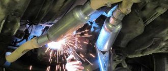
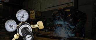
Semi-automatic or argon arc welding
To restore the integrity of steel tanks, it is possible to seal cracks using a semi-automatic device with the supply of shielding gas to the welding zone. The container is pre-washed, filled with water, or a continuous supply of carbon dioxide is provided (to prevent the formation of explosive mixtures). The welding site is pre-cleaned of traces of dirt and oil; cleaning the seam from scale is not required.
It is recommended to apply a layer of primer and cover the tank with paint or mastic that reduces the rate of external corrosion (it is impossible to protect the tank from the effects of water from the inside).
Fuel tank repair using cold welding
If using a welding machine is impossible (for example, emergency repairs are required in the field), then the tightness of the tank can be restored using epoxy resin-based compounds. The material is applied to the damaged area, the hardener introduced into the composition ensures the polymerization of the composition.
Cold welding has good adhesion to the cleaned metal, but does not withstand vibrations and mechanical influences.
If the crack is located under the mounting clamp, then repairing the fuel tank by cold welding is impossible.
How to choose welding
When selecting a composite material for sealing a crack, it is necessary to use mixtures that are resistant to petroleum products. This information is indicated by manufacturers on packages. An example is the Mastix Aqua cold weld, specially designed for restoring the seal of fuel tanks made of sheet steel or molded plastic. After combining the components, the mass is applied to the surface (processing of wet or fuel-coated walls is allowed), polymerization occurs in 1.5 hours (at +20°C).
Cold welding Mastix Aqua is designed specifically for restoring the tightness of fuel tanks.
Instructions for sealing a crack
To restore the tightness of the tank by cold welding, you must:
Using Epoxy Resin
Repair algorithm using epoxy resin:
Soldering
Compared to cold welding, fuel tank soldering is more resistant to mechanical stress and external factors. To eliminate a leak, prepare a patch 4-5 cm larger than the area of damage. Repair of plastic products is carried out on the outer part of the walls of the gas tank with a 250-watt soldering iron. When sealing, you need to select a patch from the same material. The type of plastic is indicated on each part. Most often, gas tanks are made of ABS, polypropylene or polyamide.
For high-quality adhesion, a substrate of fine reinforcing mesh made of metal or copper is required. The substrate is fused into the wall of the gas tank, evenly distributing liquid plastic over the entire surface of the defect until a new uniform coating appears. The procedure is performed quickly so that the plastic does not harden, otherwise sagging will form.
Plastic tank repair
Since the 90s last century, a massive replacement of steel tanks with plastic tanks, characterized by corrosion resistance and reduced weight, began. An additional advantage was the ability to manufacture containers of complex geometric configurations (to increase capacity when located inside a niche under the body floor).
The polyethylene used for casting has high mechanical strength and elasticity; the tank can restore its original configuration after hitting an obstacle.
Preparing the gas tank
Preparing a tank for repair consists of the following steps:
Seal the crack
Algorithm for repairing a tank with glue:
Soldering
For soldering you need a hair dryer, an electric soldering iron with a power of 40-60 W with a flat tip and sheet plastic. Detected cracks must first be repaired with a heated soldering iron. Then strips of plastic should be applied, heating the joint line with a stream of hot air from a hair dryer (temperature +330°...+350°C). It is necessary to go along the edges of the patch with a soldering iron, providing additional sealing.
To increase strength, you can apply another layer of plastic strips directed perpendicular to the primary patch. After soldering is completed, the restored surface must be treated with an abrasive tool. For soldering, polyethylene strips from fender liners (for example, from VAZ cars) with a thickness of at least 2.5 mm are used. The width and length of the patch blanks are selected depending on the size of the area being repaired.
Using a rivet or self-tapping screw
To eliminate minor damage on the road, use a screw with a piece of rubber, which is screwed into a hole in the tank. Some owners use aluminum blind rivets instead of screws. Rubber that swells under the influence of petroleum products additionally seals the damaged area. The technology is not highly reliable and is suitable for emergency repairs. It is recommended to restore the seal using epoxy glue or soldering.
How to solder the gas tank without removing it?
To seal a plastic gas tank, you can use fiberglass and epoxy resin. Before sealing, clean the surface, then apply a layer of fiberglass and impregnate with resin. Allow the surface to dry, then repeat the procedure.
Interesting materials:
When to do cardio for weight loss? When should you start training your puppy? When to Harvest Brussels Sprouts? When did Kutuzov take command of the Russians? Who should not use electric toothbrushes? Who are the heretics? Who was born to Liza Arzamasova? Where to enter a promotional code in Sunlight? Is it possible to wash vinyl wallpaper? Is it possible to wash foam wallpaper?
Repair using electric welding
Only tanks made of steel sheet can be restored by electric welding. After removing the remaining fuel, it is necessary to fill the tank with water, remove traces of rust and dirt from the repair site, and then weld the crack. Since the wall thickness does not exceed 1.5 mm, it is necessary to set the minimum welding current, otherwise the sheet may burn through. After completing the welding work, the seam should be cleaned of scale, treated with primer, and covered with a layer of bitumen mastic to protect it from external influences (road dirt and reagents).
Inverter
It is usually used to speed up welding work; this device uses high-frequency currents (up to 2000 Hz). Its advantages include compact dimensions, high welding speed, the ability to work at low voltage and ease of use, allowing even novice welders to weld a car body.
The disadvantages of the inverter include high cost, sensitivity to dust, and the inability to weld metal thicker than 3 mm.
Leak test
For testing, it is necessary to close all holes in the tank and create an excess pressure within 1.2-1.5 atm. The sealed tank does not allow air to pass through; the parameter is checked using a pressure gauge.
You can apply a soap solution to the outside of the tank; in case of leakage, bubbles will form on the surface.
In automobile facilities, tanks are tested by filling them with kerosene; the tank is considered sealed if there are no signs of leakage when the tank is kept filled for 10-12 hours.
Source