Quite often, to build a welding inverter, the main three types of high-frequency converters are used, namely converters connected according to the following circuits: asymmetric or oblique bridge, half-bridge, and full bridge. In this case, resonant converters are subtypes of half-bridge and full-bridge circuits. According to the control system, these devices can be divided into: PWM (pulse width modulation), PFM (frequency control), phase control, and there may also be combinations of all three systems.
All of the above converters have their pros and cons. Let's deal with each one separately.
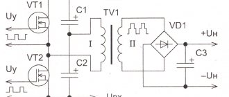
Half bridge system with PWM
The block diagram is shown below:
This is perhaps one of the simplest, but no less reliable push-pull converters. The “surge” of the voltage of the primary winding of the power transformer will be equal to half the supply voltage - this is a drawback of this circuit. But if you look from the other side, you can use a transformer with a smaller core without fear of entering the saturation zone, which is also a plus. For welding inverters with a power of about 2-3 kW, such a power module is quite promising.
Since power transistors operate in hard switching mode, drivers must be installed for their normal operation. This is due to the fact that when operating in this mode, transistors require a high-quality control signal. It is also necessary to have a no-current pause in order to prevent the simultaneous opening of transistors, which will result in the failure of the latter.
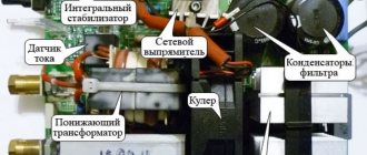
Power part with power supply and drivers.
………. The welding inverter shown in the diagram is built according to the single-cycle forward flow diagram. Unipolar pulses of rectified mains voltage with a filling of no more than 42% are supplied to the primary winding of the welding transformer using two switches. The magnetic core of the transformer experiences one-sided magnetization. During pauses between pulses, the magnetic circuit is demagnetized in a so-called private loop. The demagnetizing current, thanks to the reverse-connected diodes, returns the magnetic energy stored in the transformer core back to the source, recharging the capacitors (2 x 1000 µF x 400 V) of the drive.
Resonant half bridge
A rather promising view of a half-bridge converter, its circuit is shown below:
A resonant half bridge will be a little simpler than a PWM half bridge. This is due to the presence of resonant inductance, which limits the maximum current of transistors, and switching of transistors occurs at zero current or voltage. The current flowing through the power circuit will be in the form of a sinusoid, which will remove the load from the capacitor filters. With this design of the circuit, drivers are not necessarily needed; switching can be carried out by a conventional pulse transformer. The quality of control pulses in this circuit is not as significant as in the previous one, but there should still be a no-current pause.
In this case, it is possible to do without current protection, and the shape of the current-voltage characteristic of the current-voltage characteristic will have a falling form, which does not require its parametric formation.
The output current will be limited only by the magnetizing inductance of the transformer and, accordingly, can reach quite significant values in the event that a short circuit occurs. This property has a positive effect on the ignition and burning of the arc, but it also must be taken into account when selecting output diodes.
Typically, the output parameters are adjusted by changing the frequency. But phase regulation also provides some advantages and is more promising for welding inverters. It allows you to bypass such an unpleasant phenomenon as the coincidence of a short circuit with resonance, and also increases the range of regulation of output parameters. The use of phase control can allow the output current to be varied in the range from 0 to Imax.
catalogue of articles
Power transistors are the heart of a resonant inverter!
The reliability of the entire device depends on the correct choice of power transistors. Technological progress does not stand still; many new semiconductor devices appear on the market, and it is quite difficult to understand this diversity. Therefore, I will try to briefly outline the basic principles for choosing power switches when building a powerful resonant inverter. The first thing you need to start with is an approximate determination of the power of the future converter. I will not give abstract calculations, and will immediately move on to our welding inverter. If we want to get 160 amperes in an arc at a voltage of 24 volts, then by multiplying these values we will get the useful power that our inverter must deliver without burning out. 24 volts is the average burning voltage of an electric arc 6-7 mm long; in fact, the length of the arc changes all the time, and accordingly the voltage on it changes, and the current also changes. But for our calculation this is not very important! So, multiplying these values, we get 3840 W, approximately estimating the converter efficiency of 85%, you can get the power that the transistors must pump through themselves, this is approximately 4517 W. Knowing the total power, you can calculate the current that these transistors will have to switch. If we are making a device to operate from a 220 volt network, then simply dividing the total power by the network voltage, we can obtain the current that the device will consume from the network. That's approximately 20 amps! I get a lot of emails asking if it is possible to make a welding machine so that it can run on a 12 volt car battery? I think these simple calculations will help all those who like to ask them. I foresee the question of why I divided the total power into 220 volts, and not into 310, which is obtained after rectifying and filtering the mains voltage, everything is very simple, in order to maintain 310 volts with a current of 20 amperes, we will need a filter capacity of 20,000 microfarad! And we set no more than 1000 uF. We seem to have sorted out the current value, but this should not be the maximum current of the transistors we have chosen! Now in the reference data of many companies two maximum current parameters are given, the first at 20 degrees Celsius, and the second at 100! So, with large currents flowing through the transistor, heat is generated on it, but the rate of its removal by the radiator is not high enough and the crystal can heat up to a critical temperature, and the more it heats up, the less its maximum permissible current will be, and ultimately this may lead to destruction of the power key. Typically, such destruction looks like a small explosion, in contrast to a voltage breakdown, when the transistor simply burns out quietly. From here we conclude that for an operating current of 20 amperes it is necessary to choose transistors whose operating current will be at least 20 amperes at 100 degrees Celsius! This immediately narrows our search area to several dozen power transistors. Naturally, having decided on the current, we must not forget about the operating voltage; in a bridge circuit with transistors, the voltage does not exceed the supply voltage, or, more simply put, cannot be more than 310 volts, when powered from a 220 volt network. Based on this, we select transistors with a permissible voltage of at least 400 volts. Many may say that we will immediately set it to 1200, this will supposedly be more reliable, but this is not entirely true, transistors are of the same type, but for different voltages they can be very different! Let me give you an example: IGBT transistors from IR type IRG4PC50UD - 600V - 55A, and the same transistors for 1200 volts IRG4PH50UD - 1200V - 45A, and that’s not all the differences, with equal currents on these transistors there is a different voltage drop, on the first 1.65V, and on the second 2.75V! And with currents of 20 amperes, this is an extra watt of loss, moreover, this is power that is released in the form of heat, it must be removed, which means you need to almost double the radiator! And this is not only additional weight, but also volume! And all this must be remembered when choosing power transistors, but this is just the first estimate! The next stage is the selection of transistors according to the operating frequency; in our case, the parameters of the transistors must be maintained at least up to a frequency of 100 kHz! There is one little secret, not all companies provide cutoff frequency parameters for operation in resonant mode, usually only for power switching, and these frequencies are at least 4 - 5 times lower than the cutoff frequency when using the same transistor in resonant mode. This slightly expands the area of our search, but even with such parameters there are several dozen transistors from different companies. The most affordable of them, both in price and availability, are transistors from IR. These are mainly IGBTs, but there are also good field-effect transistors with a permissible voltage of 500 volts, they work well in such circuits, but are not very convenient to fasten, there is no hole in the case. I will not consider the parameters for turning on and off these transistors, although these are also very important parameters, I will briefly say that for normal operation of IGBT transistors, a pause between closing and opening is necessary for all processes inside the transistor to complete, at least 1.2 microseconds! For MOSFET transistors, this time cannot be less than 0.5 microseconds! These are actually all the requirements for transistors, and if all of them are met, then you will get a reliable welding machine! Based on all of the above, the best choice is IR transistors such as IRG4PC50UD, IRG4PH50UD, field-effect transistors IRFPS37N50A, IRFPS40N50, IRFPS43N50K. These transistors have been tested and shown to be reliable and durable when operating in a resonant welding inverter. For low-power converters whose power does not exceed 2.5 kW, you can safely use IRFP460.
www.sibelektrod.ru
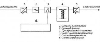
Asymmetrical or oblique bridge
This is a single-ended, forward-flow converter, the block diagram of which is given below:
This type of converter is quite popular both among ordinary radio amateurs and among manufacturers of welding inverters. The very first welding inverters were built precisely according to such schemes - an asymmetric or “oblique” bridge. Noise immunity, a fairly wide range of output current regulation, reliability and simplicity - all these qualities still attract manufacturers to this day.
Quite high currents passing through transistors, an increased requirement for the quality of the control pulse, which leads to the need to use powerful drivers to control transistors, and high requirements for installation work in these devices and the presence of large pulse currents, which in turn increase the requirements for capacitors filters are significant disadvantages of this type of converter. Also, to maintain normal operation of the transistors, it is necessary to add RCD chains - snubbers.
But despite the above disadvantages and the low efficiency of the device, an asymmetric or “oblique” bridge is still used in welding inverters. In this case, transistors T1 and T2 will operate in phase, that is, they will close and open simultaneously. In this case, energy accumulation will occur not in the transformer, but in the inductor coil Dr1. That is why, in order to obtain the same power with a bridge converter, double the current through the transistors is required, since the duty cycle will not exceed 50%. We will consider this system in more detail in the following articles.
How does a welding inverter work?
The formation of a high current, with the help of which an electric arc is created to melt the edges of the parts being joined and the filler material, is what any welding machine is designed for. For the same purposes, an inverter apparatus is also needed, which allows the generation of welding current with a wide range of characteristics.
In its simplest form, the principle of operation of the inverter looks like this.
- Alternating current with a frequency of 50 Hz from a regular electrical network is supplied to the rectifier, where it is converted into direct current.
- After the rectifier, the direct current is smoothed using a special filter.
- From the filter, direct current flows directly to the inverter, whose task is to convert it again into alternating current, but at a higher frequency.
- After this, using a transformer, the voltage of the alternating high-frequency current is reduced, which makes it possible to increase its strength.
Block diagram of an inverter type welding machine
In order to understand the importance of each element of the electrical circuit diagram of an inverter device, it is worth considering its operation in more detail.
Full bridge with PWM
It is a classic push-pull converter, the block diagram of which is shown below:
This circuit allows you to receive power 2 times more than when turning on the half-bridge type and 2 times more than when turning on the “oblique” bridge type, while the magnitudes of the currents and, accordingly, losses in all three cases will be equal. This can be explained by the fact that the supply voltage will be equal to the “drive” voltage of the primary winding of the power transformer.
In order to obtain the same power with a half-bridge (drive voltage 0.5 Usupply), the current required is 2 times! less than for the half-bridge case. In a full bridge circuit with PWM, the transistors will operate alternately - T1, T3 are on, and T2, T4 are off and, accordingly, vice versa when the polarity changes. Through a current transformer, the values of the amplitude current flowing through this diagonal are monitored and controlled. To regulate it, there are two most commonly used methods:
- Leave the cut-off voltage unchanged, and change only the length of the control pulse;
- Change the cut-off voltage level according to data from the current transformer while leaving the duration of the control pulse unchanged;
Both methods can allow changes in the output current within fairly large limits. A full bridge with PWM has the same disadvantages and requirements as a half bridge with PWM. (See above).
Inverter setup
………. The power section is still de-energized. We connect the previously tested power supply to the control unit and plug it into the network. All eights on the indicator will light up, then the relay will turn on and, if the thermostat contacts are closed, the indicator will show a current setting of 20 A. Using an oscilloscope, we check the voltage at the gates of the keys. There should be rectangular pulses with fronts of no more than 200 ns, a frequency of 40-50 kHz, a voltage of 13-15 V in the positive region and 10 V in the negative. Moreover, in the negative region the pulse should be noticeably longer.
………. If everything is so, we assemble the entire inverter circuit and connect it to the network. The display will first display eights, then the relay should turn on and the indicator will show 20 A. By clicking the buttons, we try to change the current setting. Changing the current setting should proportionally change the voltage on capacitor C1. If, after changing the current setting, you do not press the buttons for more than 1 minute, the task will be recorded in non-volatile memory. The message “RESERVE” will appear briefly on the indicator. The next time the inverter is turned on, the current command value will be equal to the value that was recorded.
Resonance Bridge
It is the most promising high-frequency converter circuit for a welding inverter, the block diagram of which is shown below:
A resonant bridge is not much different from a full PWM bridge. The difference is that with a resonant connection, a resonant LC circuit is connected in series with the transformer winding. However, its appearance radically changes the process of power transfer. Losses will decrease, efficiency will increase, the load on input electrolytes will decrease and electromagnetic interference will decrease. In this case, drivers for power transistors should be used only if MOSFET transistors are used that have a gate capacitance of more than 5000 pF. IGBTs can only get by with a pulse transformer. More detailed descriptions of the schemes will be given in subsequent articles.
The output current can be controlled in two ways - frequency and phase. Both of these methods were described in a resonant half-bridge (see above).
Advantages and disadvantages
It is important to attribute the following to the strengths of the equipment:
- high efficiency,
- significant power density,
- assortment in stock,
- scope of application.
The disadvantages are also familiar to everyone, we are talking about the high cost of products. The units do not have a long service life. When the electronic board burns out, it is impossible to do anything.
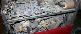
Electronic board
The problem lies in the insecurity of the case. The workplace is usually full of dust and dirt. All this settles on the internal elements of the structure and a failure occurs.
You may be interested in this Definition of hidden wiring
Full bridge with dissipation choke
Its circuit is practically no different from the circuit of a resonant bridge or half-bridge, only instead of a resonant LC circuit, a non-resonant LC circuit is connected in series with the transformer. Capacitance C, approximately C≈22μF x 63V, works as a balancing capacitor, and the inductive reactance of the inductor L as a reactance, the value of which will change linearly depending on the change in frequency. The converter is controlled by frequency. As we know from electrical engineering, as the voltage frequency increases, the inductance resistance will increase, which will reduce the current in the power transformer. Quite a simple and reliable method. Therefore, a fairly large number of industrial inverters are built according to this principle of limiting output parameters.
Easy to repeat and manufacture Lipina welding inverter (oblique bridge)
Translation from light-faced into Russian. ====================================== Address of the Congress of Intelligentsia to the citizens of Russia. We, Russian(?) citizens, express solidarity with the open letter of more than 200 independent regional deputies directed against the adoption of amendments to the Constitution initiated by President V.V. Putin. -We are against the Russian Federation ensuring the protection of its sovereignty and territorial integrity. -We are against the Russian Federation, united by a thousand-year history, preserving the memory of its ancestors who passed on to us the ideals and faith in God, as well as continuity in the development of the Russian state, recognizing the historically established state unity. -We are against the Russian Federation honoring the memory of the defenders of the Fatherland and ensuring the protection of historical truth. -We, the undersigned, oppose children being the most important priority of Russian state policy. We do not want the State to create conditions conducive to the comprehensive spiritual, moral, intellectual and physical development of children, instilling in them patriotism, citizenship and respect for elders. -We oppose the idea that the state language of the Russian Federation throughout its entire territory should be Russian as the language of the state-forming people included in the multinational union of equal peoples of the Russian Federation. -We do not want republics to have the right to establish their own official languages. -We do not believe that the Russian Federation should guarantee the rights of indigenous peoples in accordance with generally accepted principles and norms of international law and international treaties of the Russian Federation. -Moreover, we oppose the protection of the cultural identity of all peoples and ethnic communities of the Russian Federation, and especially any guarantees for the preservation of ethnocultural and linguistic diversity. -In our deep and handshake conviction, the Russian Federation should not provide support to compatriots living abroad in the exercise of their rights, ensuring the protection of their interests and preserving the all-Russian cultural identity. -The capital of the Russian Federation should under no circumstances be the city of Moscow! -The Russian Federation should under no circumstances respect the work of citizens and ensure the protection of their rights. It is completely unacceptable for the state to guarantee a minimum wage of no less than the subsistence level of the working population as a whole in the Russian Federation! -No social insurance, especially targeted social support for citizens and indexation of social benefits and other social payments! I\We will fight with all our might to prevent such a mockery of democratic values under any circumstances! -We call on the leaders of democratic political and public organizations to unite with the goal of peacefully forcing the authorities to hold parliamentary elections in 2021 on the terms of political pluralism and democracy. We invite everyone who shares this position to choose one of two solutions: vote against the amendments to the Constitution or ignore the voting procedure itself. “Firing list” Lev Ponomarev, human rights activist Valery Borshchev, human rights activist Lyudmila Ulitskaya, writer Svetlana Gannushkina, human rights activist Andrei Smirnov, film director Oleg Basilashvili, People's Artist of the USSR Liya Akhedzhakova, People's Artist of the Russian Federation Andrei Makarevich, musician, poet Vladimir Mirzoev, director Natalya Fateeva, people's RSFSR artist Leonid Gozman, psychologist, publicist Dmitry Bykov, writer Viktor Shenderovich, writer Harry Bardin, animator director Lev Timofeev, writer Zoya Svetova, journalist Alexey Malobrodsky, theater producer Joseph Raikhelgauz, director, People's Artist of Russia Grigory Mikhnov-Vaitenko, sacred minister Yuri Bogomolov, film critic and television critic.. And other persons under the spoiler. Original letter in the original language: https://echo.msk.ru/blog/echomsk/2657940-echo/
The power part of our homemade inverter-type semi-automatic welding machine is based on an asymmetric bridge circuit, or, as it is also called, an “oblique bridge”. This is a single-ended forward converter. The advantages of such a scheme are simplicity, reliability, minimal number of parts, and high noise immunity. Until now, many manufacturers produce their products using the “oblique bridge” design. You also cannot do without disadvantages - these are large pulse currents from the power supply, lower efficiency than in other circuits, and large currents through the power transistors.
Correct purpose
Welding machines are suitable for productive work at home, as well as in workshops. The variety of functions in the devices makes them versatile. Standard welding inverters provide constant welding current, therefore they are considered universal units. They are suitable for welding and cutting ferrous and non-ferrous metals.
Semi-automatic is distinguished by a thin and even seam, leaving virtually no traces behind. The plasma cutter is in demand in the industrial sector and is suitable for professional work. Metal cutting occurs at high speed. Various types of blanks are allowed.
Plasma cutters
Interesting ! Plasma cutters are suitable for long cuts, for example, bronze or aluminum.
Argon-arc welding machines are considered more suitable for non-ferrous metals. A significant depth of welding is provided and there are practically no restrictions. Spot welding models can also be called spotters and are applicable in metalworking enterprises. Point machines are suitable for cutting large products.
Argon-arc welding machines
Control board
The following inverter components are installed on the control board: a master oscillator with a galvanic isolation transformer, current and voltage feedback units, a relay control unit, a thermal protection unit, and an “anti-stick” unit.
Printed circuit board of the control unit in .lay format
Master oscillator
The current control unit (for MMA mode) and the master oscillator (OG) are assembled on LM358N and UC2845 microcircuits. UC2845 was chosen as the MG, rather than the more common UC3845 due to the more stable parameters of the former.
The generation frequency depends on the elements C10 and K19, and is calculated by the formula: f = (1800/(R*C))/2, where R and C are in kilo-ohms and nanofarads, the frequency is in kilohertz. In this circuit, the frequency is 49KHz.
Another important parameter is the fill factor, calculated using the formula Kzap = t/T. It cannot be more than 50%, and in practice it is 44-48%. It depends on the ratio of denominations C10 and R19. If the capacitor is taken as small as possible, and the resistor as large as possible, then Kzap will be close to 50%.
The generated SG pulses are fed to the VT5 switch, which operates on the T1 galvanic isolation transformer (TGR), wound on an EE25 core, used in electronic units for starting fluorescent lamps (electronic ballasts). All windings are removed and new ones are wound according to the diagram. Instead of the IRF520 transistor, you can use any of this series - IRF530, 540, 630, etc.
Datasheet BS170 Datasheet IRF520 Datasheet LM358N Datasheet UC2845 Documentation for small cores EE, EI and others
Current feedback
As mentioned earlier, for arc welding it is important to have a stable output current, for semi-automatic welding it is important to have a constant voltage. Current feedback is organized on the TT current transformer; it is a ferrite ring of size K 20 x 12 x 5, placed on the lower (according to the diagram) terminal of the primary winding of the power transformer. Depending on the primary winding current T2, the pulse width of the master oscillator decreases or increases, maintaining the output current unchanged.
Voltage feedback
An inverter-type semi-automatic welding machine requires voltage feedback; for this, in MAG mode, switch S1.1 supplies the voltage from the device output to the output voltage adjustment unit, assembled on elements R55, D18, U2. Powerful resistor K50 sets the initial current. And with contacts S1.2, the key on the transistor VT1 short-circuits the regulator R2 to the maximum current, and the key VT3 disables the “anti-stick” mode (switching off the GB when the electrode sticks). Documentation for controlled zener diode KA431 Documentation for optocoupler EL817
Thermal protection block
A homemade semi-automatic welding machine includes an overheating protection circuit: this is provided by a unit on transistors VT6, VT7. Temperature sensors at 75 degrees C (there are two of them, normally closed, connected in series) are installed on the radiator of the output diodes and on one of the radiators of the power transistors. When the temperature is exceeded, transistor VT6 shorts pin 1 of the UC2845 to ground and disrupts the generation of pulses.
Relay control unit
This block is assembled on a DD1 CD4069UB microcircuit (analogous to 561LN2) and a VT14 BC640 transistor. These elements provide the following operating mode: when you press the button, the gas valve relay is immediately turned on, after about a second, the VT17 transistor allows the generator to start and at the same time the pull-out mechanism relay turns on.
The relays that control the “pulling” and the gas valve, as well as the fans, are powered by the stabilizer on the MC7812 mounted on the control board.
Procedure for repairing devices
Failure and failure of the welding inverter can occur either due to a serious breakdown or due to a minor malfunction. Before contacting a service center or a familiar technician, it makes sense to consider the option of doing the repair yourself, especially if the owner has specialized education or amateur radio skills. The inverter should be disassembled, cleaned and carefully inspected from the inside, as the problem may be excess dust or some loose wiring, and no major repairs are really needed.
If you decide to carry out repairs yourself, then the following minimum set of tools is required:
- Digital multimeter. The most common one, the “diode test” function is optional, since all semiconductors can be checked in resistance measurement mode.
- Soldering iron with accessories. A soldering station is better, but you can get by with a soldering iron with a thin tip of 40–60 W.
- Screwdrivers, pliers, wire cutters, tweezers.
It is often written that to check the condition of an inverter device you definitely need an oscilloscope. But this is a different level of knowledge and skills with different recommendations for troubleshooting. Our actions for diagnosing and repairing the inverter will be limited to a visual inspection, continuity testing, basic measurements of the condition of the main elements of the inverter’s electronic circuit and their replacement in the event of a malfunction. If all this does not bring results, then you need to contact specialized specialists.
The procedure for the first stage is as follows:
- Remove the housing and clean the inverter from dust with compressed air. Select the pressure so as not to damage printed circuit boards and electronic components.
- Check the condition of the fan blades and the ease of their rotation. If problems are found, replace them with new ones. Check that all wires and connectors are securely connected.
- Check the connection and condition of the welding current adjustment potentiometer. In case of malfunction, repair or replacement.
- Inspect the windings of transformers and chokes for burning. If there are defects, dismantle and send for inspection or immediately rewind.
- Check the elements of the power circuit (capacitors, charging resistor, diodes, transistors) for damage to the external housing. If defects are found, replace with the same or analogues.
- Carry out an external inspection of the control system printed circuit board. If there are damaged elements, then carefully remove them and replace them with new ones (if you have never soldered printed circuit boards, then it is better not to do this, but immediately contact a specialist).
If, after an external inspection and elimination of detected problems, the inverter does not turn on or operates incorrectly, it is necessary to diagnose individual circuits and power elements (see below).
Inverter diagnostics
Testing of semiconductor electronic components is carried out by measuring the resistance at their terminals by changing the polarity of the multimeter. In one case it should be close to zero, in the other - infinitely large.
Before you begin diagnosing the inverter, you must connect a 100÷150 W incandescent light bulb in series with it, which will stabilize the current and serve as protection against short circuits. In addition, by the glow of the light bulb one can judge the working condition of capacitors and power transistors.
We diagnose the inverter in the following sequence:
- Checking the power diodes of the output rectifier. We measure the resistance at the output terminals of the inverter with a multimeter. One way should be zero, the other should be infinity. If this is not the case, then we proceed to repair: we identify the faulty diode and replace it.
- Checking the power transistors of the RF converter. First you need to determine the type of arrangement of the transistor pins. We measure for “breakdown” by changing the polarity between the gate and the other two terminals. If it is zero in both directions, then the transistor is faulty and must be replaced.
- Checking the diodes of the LF rectifier. Here the diodes are connected in a bridge circuit, so first you need to determine the four contact points. At zero in both directions the diode must be replaced.
- If all power semiconductors of the devices are in good condition, you can connect the inverter to the network. In this case, the light bulb connected in series with it will first flash for a few seconds, and then, as the LF rectifier capacitors charge, it will begin to dim noticeably. If at least one of the transistors of the RF converter is broken, the light bulb will burn at full intensity.
- The inverter can then be turned on and off several times using the key on the front panel. After this, it is necessary to measure the open circuit voltage in several positions of the current regulator (it will be slightly less than the nominal one).
Before repairing the welding inverter, it must be disconnected from the power supply. The light bulb circuit can only be used at idle. It is best to check the device under load with a ballast rheostat.
Replacing transistors
When repairing a welding inverter, you may have to replace transistors, zener diodes, resistors and other electronic parts. To do this, you need to have some skills in soldering such products. When replacing transistors (IGBT and MOSFET), you must remember that they can fail under the influence of static electricity. It is recommended to work with them on antistatic surfaces and wearing wristbands to protect against static. In fact, few people fully follow these instructions, but it is still necessary to know about them.
In order to replace the power transistor, you need to unscrew the screw that holds it to the radiator, separate its body from the surface, and then carefully unsolder it. Installation of the new transistor is carried out in the reverse order; before pressing it with a screw to the radiator, you need to apply a thin layer of heat-dissipating paste to the contact point.
Rectifier repair
The inverter contains three rectifiers: a half-wave output and two bridge rectifiers: an input and an internal power supply (“standby”). The first one contains two diodes and is checked with a multimeter through the input terminals of the inverter, and bridge diodes - at four points (on the connectors or on the board). When repairing rectifiers, diodes, capacitors and ballast resistors are most often replaced. There are no special precautions when soldering these elements, although when replacing parts of the internal power supply you need to be extremely careful: they are installed on the printed circuit board. The diodes of the input and output rectifiers are mounted on radiators. When installing a new element, be sure to use heat-dissipating paste before fixing it with a clamping screw.
Capacitor diagnostics
The main reasons for the failure of electrolytic capacitors are mechanical damage, significant excesses of the rated voltage, failure of internal contacts and aging. In the first two cases, malfunctions can be detected visually, while the ends of most models of electrolytic capacitors have special notches that rise or open when the electrolyte “explodes” (see photo below).
Figure 7 — Capacitor diagnostics
Hidden faults are quite easily detected by a device with a capacitance measurement function or a conventional multimeter. In the latter case, the pre-discharged capacitor initially shows a small resistance, which increases to infinity as it is charged from the multimeter source. When measuring at the contacts of a faulty capacitor, the device shows either an open circuit or some kind of constant resistance.
Control board repair
If simple diagnostics with a multimeter and subsequent repairs do not give the desired result, then the source of the problem is most likely the control board. Without an oscilloscope, here you can only check the voltage values at the contact points of the board indicated on the diagram, as well as measure the supply voltages and ring the semiconductor devices (which, most likely, will have to be soldered). In addition, to repair the control board, you need good knowledge of radio electronics and the ability to understand the circuits of electronic devices. For those who do not have such qualifications, there is only one option left - to a service center or to a specialist with a good reputation.
We think this article lists all the possible steps to diagnose inverter faults using a multimeter. If we missed any important points, write about it in the comments and tell us about your experience in repairing an inverter device.
PS. Experienced and serial production of printed circuit boards with a guarantee can be viewed at this link.
Power unit based on HGTG30N60A4 transistors
From the TGR output, pulses pre-generated by drivers on transistors VT9 VT10 are supplied to power switches VT11, ME12. “Snubbers” are connected parallel to the collector-emitter terminals of these transistors - chains of elements C24, D47, R57 and C26, D44, R59, which serve to keep powerful transistors in the range of permissible values. In the immediate vicinity of the keys there is a capacitor C28, assembled from 4 capacitors of 1 micron x 630v. Zener diodes Z7, Z8 are necessary to limit the voltage at the switch gates to 16 volts. Each transistor is installed on a radiator from a computer processor with a fan. Documentation for transistors HGTG30N60A4 Printed circuit board of the power unit in .lay format
Power transformer and rectifier diodes
The main element of the semiautomatic welding circuit is the powerful output transformer T2. It is assembled on two E70 cores, N87 material from EPCOS.
Calculation of a welding transformer
The power transformer can be wound on a different standard size; the turns are calculated using the above formula. For example, for a core 2 x E80 at f = 49Khz, turns in the primary: 16, secondary: 5.
Documentation for large EPCOS W-shaped cores
Selecting the cross-section of the wires of the primary and secondary windings, winding the transformer
We select the wire cross-section at the rate of 1mm.kv = 10A output current. This device should produce approximately 190A under load, so we take the secondary cross-section of 19mm.kv (a bundle of 61 wires with a diameter of 0.63mm). The cross section of the primary is selected 3 times smaller, i.e. 6mm.sq. (harness of 20 wires with a diameter of 0.63 mm). The cross-section of the wire depending on its diameter is calculated as: S = D²/1.27 where D is the diameter of the wire.
Winding is carried out on a frame made of 1mm PCB, without side cheeks. The frame is mounted on a wooden frame according to the dimensions of the core. The primary winding is wound (all turns in one layer). Then 5 layers of thick transformer paper, with the secondary winding on top. The coils are compressed with plastic ties. Then the frame with windings is removed from the mandrel and impregnated with varnish in a vacuum chamber. The chamber was made from a liter jar with a tight lid and a hose attached to the suction tube of the compressor from the refrigerator (you can simply dip the trans in varnish for a day, I think it will also become saturated).
When installing the transformer on the board, place an ATM receipt under the side cores (make a gap of approximately 0.05 mm). After installation on the board, the trans is compressed by a plate on two studs. To protect against parasitic high-frequency high-voltage surges, ferrite tubes (such as those found on a computer video cable) are placed on the terminals of the secondary winding, and the diodes are shunted by chains R64, C33 and R65 C34.
One terminal of the “primary” is threaded through the ring of the current transformer CT.
Semi-automatic welding circuit - rectifier diodes
The rectifier unit of our homemade device is assembled on three powerful 150EBU04 diodes installed on a common radiator with a fan. The choke for a semi-automatic welding machine is wound on iron from a TS-180 transformer and contains 12 turns of wire with a cross-section of 20 mm2. The gap between the core halves is 1.5mm.
Datasheet for diodes 150EBU04
Half-bridge power supply circuit
In general, voltage converters can be classified according to many criteria and have different circuits and operating principles.
When it comes to a half-bridge circuit, we necessarily mean push-pull pulse voltage converters (PN).
For understanding, here is a classification of the most common converters:
- Transformer (operate at low frequencies);
- Triac or thyristor (combined because the operating principle of the main elements is largely similar);
- Inverter (convert direct voltages into alternating ones);
- Pulse. Derivative options are possible here: Throttle;
- Single-stroke (essentially operating in throttle mode) With a forward-flow circuit;
- With flyback circuit.
- With the output of the middle point of the primary winding (often called Push-Pull or “Push-Pull”);
Two cycles of operation imply excitation of the windings of the pulse transformer in both directions.
One cycle - only in one direction.
All options have their advantages and disadvantages.
Now let's move directly to push-pull power supplies.
For clarity, it is best to present their simplest diagrams.
Rice. 1. The simplest circuits of push-pull power supplies
The operating principle of push-pull PNs is perfectly illustrated by the Push-Pull diagram:
1. The resulting magnetic field in the primary winding excites a current in the secondary. When a positive pulse/oscillation arrives at the output of the first winding, the transistor operates and passes current.
2. When a negative pulse arrives, the second winding with its own transistor is triggered. At this moment, the first transistor and its winding are idle. That is, they change places.
These are two strokes of push-pull work.
But the circuit can be made more complex by using more control switches (transistors). Then you can get by with only one secondary winding, which greatly simplifies the winding of the pulse transformer. This is most clearly seen in the “Bridge” diagram. Both positive and negative oscillations are applied to one winding.
If you replace half of the transistors with capacitors, you get the same “half bridge”. Capacitors act as a smoothing filter and help stabilize the voltage.
Examples of circuit diagrams
The first, quite common option.
Rice. 2. Schematic diagram
The keys are controlled by a timer; here it is built on the basis of the very popular TL-494 PWM controller. In order for the pulses of the low-power generator to become sufficient for power switches VT3 and 4, they are pre-amplified by a cascade of VT1, 2 and transformer TR1.
Current rectification occurs almost at the output of the circuit. Schottky diodes and simple smoothing filters - capacitors - are responsible for this task.
IRFZ34 mosfets can be used as transistors 1 and 2, IRFP460 as transistors 3 and 4.
The main difficulty is pulse transformers. If you want to calculate yours, it is best to use special software.
- First. Each winding has 50 turns of 0.5 mm wire.
- Second. 1 – 110 turns 0.8 mm, 2 – calculated based on the required voltage (1 turn – 2 V), 3 – 12 turns 0.8 mm.
This configuration can provide up to 500W of power. The nominal value is about 300 W.
The second option is more complicated. But here are provided:
- Protection against short circuit and overloads;
- Soft (soft) start;
- Noise filters at input and output.
Rice. 3. Schematic diagram
The IR2153 chip was chosen as the driver here.
Readers' opinions
No comments yet. Your comment will be the first.
You can leave your comment, opinion or question on the above material:
The Chinese make you happy or Old songs about the main thing
Actually, the Chinese have been surprising for a long time with irrational Asian thinking.. The last case stuck to the Kaiser NBC-200 welding machine... This is not know-how.. But considering the launch of a push-pull circuit from a single-cycle controller became a question the day before yesterday. What's wrong? There is no bridge or half-bridge. the keys work synchronously...The secondary rectifier also works according to a push-pull circuit, which equalizes the time asymmetry between the PH and OX in the constant output. To view the link, you must register on the Forum
Show more (19)
What types of welding oscillators are there?
The welding oscillator is not the main device for welding work.
It is not possible to use it yourself, since it does not have much power capable of melting and joining metals. Its main function is to ignite the arc without touching the electrode to the working surface, and then maintain its stable state. This effect is possible due to the generation of a high-frequency high-voltage voltage by the device, capable of breaking down the air gap between the electrode and the metal. The main welding current is already beginning to flow across the bridge of this breakdown. There are the following types of welding oscillators:
- Device with continuous operation mode;
- Device with pulse power supply;
- Device with storage capacitors.
Welding oscillator circuit
Continuous Oscillator
A device of this type produces a current whose frequency reaches 250 kHz, and the voltage amplitude can reach 6 kilovolts. This electricity is additionally superimposed on the main welding current, the arc instantly ignites at a distance from the workpiece and remains stable at any amplitude values of the main current due to the high frequency. The current of the welding oscillator does not pose a real threat to the operator, since it has little power.
The circuit for connecting the device to a common network with a welding machine can be performed in parallel or in series. Sequential switching is more appropriate. There is no need to apply additional high voltage protection for the device.
Pulse oscillator
The design of this type of oscillator is convenient to use if welding is carried out with an alternating current. The equipment is capable of holding the arc at the moment of transition of the polarity of electricity, which is observed constantly. The continuous oscillator circuit loses in this sense. The pulse device also ignites the arc at the initial moment of time without physical contact.
Oscillator with storage capacitors
A device whose circuit contains storage capacitors operates in a charge-discharge mode. A special charging module is used to saturate the capacitors. At the initial moment of time, the charged capacitors give up energy to the arc and, disconnecting from the discharge circuit, are connected to the charging module. If there is a threat of arc failure, the synchronizing module again switches the spark gaps to the working line of the welding machine.
Structure and operating principles of bridges
Laboratory work No. 5
Operation of bridges and switches
Based on the STP link layer protocol
TCP/IP protocol stack
Theoretical part
Structure and operating principles of bridges
The integration of modern networks is carried out both with the help of routers and with the help of bridges and switches. The main difference between them is that networking using bridges and switches occurs at the data link layer of the Open Systems Interconnection (OSI) reference model, while a router uses the network layer; In addition, these devices support various algorithms when moving information across the network.
A bridge is a device that ensures the interconnection of several local networks by transmitting frames from one network to another. Unlike hubs, which check electrical signals, a bridge only checks frames. Bridges do not repeat noise, errors or broken frames. The bridge acts as an end node in relation to each of the networks it connects. It receives a frame, stores it in buffer memory, and analyzes the destination address of the frame. If the frame belongs to the network from which it was received, the bridge does not respond to this frame. If a frame needs to be transmitted to another network, the bridge must access its shared media according to the same rules as a normal node.
There are two main types of bridges - local and global (remote). They differ in their network ports. Local bridges are equipped with ports for connecting to a LAN. Typical media for such environments are coaxial or fiber optic cable, as well as twisted pair wires. An important property of local bridges is their ability to connect networks using different media. For example, they can be used to connect a coaxial cable network to a fiber optic cable network, or either of them to a twisted pair network.
Global bridges are those bridges whose ports are consistent with media for transmitting information over long distances. Global bridges can have interfaces for both long-distance transmission and local ones.
According to their operating principle, bridges are divided into two main types. The first type of bridge performs what is called source routing. In such a network, bridges do not need to maintain an address database. They determine the path of a frame based on the information stored in the frame itself.
Bridges of the second type are called “transparent”. Transparent bridges, in turn, are divided into three subtypes:
· transparent bridges - used to connect networks with identical protocols at the data link and physical levels of the OSI model (Ethernet - Ethernet, Token Ring - Token Ring, etc.);
· broadcasting bridges - used to combine networks with different protocols at the data link and physical levels;
· encapsulating bridges - designed to combine networks with the same protocols (for example, Ethernet) at the data link and physical level through a network with other protocols (for example, FDDI).
Clear bridges are the most common type. For them, the network is represented by sets of physical addresses of devices used at the data link layer. Bridges rely on these addresses to decide whether to transmit a frame. In this case, the frame is written to the internal buffer of the bridge. Bridges do not have access to network layer information about network addresses. They “know” nothing about the topology of connections between segments or networks.
When frames are transmitted inside a transparent bridge, they are regenerated and transmitted from one port to another. The bridge uses the source address to automatically build its database of device addresses, also called a physical address table. This table establishes whether the station address belongs to any bridge port. All operations that the bridge performs are associated with this database. The internal structure of the bridge is shown in Fig. 5.1.
All bridge ports operate in the so-called promiscuous frame capture mode, that is, all frames arriving at the port are stored in its buffer memory. With this mode, the bridge monitors all traffic transmitted on segments attached to it and uses frames passing through it to study the composition of the network.
The functional basis of bridges consists of the following functions: training, filtering, transmission and broadcasting.
When the bridge receives a frame, it checks its integrity and checksum. Invalid frames are discarded. The bridge then compares the sender's address with the addresses in the database. If the sender's address is not yet in the database, it is added to it. Thus, the bridge learns the addresses of devices on the network, and the process of its learning occurs (Fig. 5.2). Thanks to the bridge's learning capabilities, new devices can be added to the network without the need to reconfigure the bridge.
In addition to the sender's address, the bridge also analyzes the recipient's address. The bridge compares the address of the frame recipient with the addresses stored in its database. If the recipient's address belongs to the same segment as the sender's address, then the bridge “filters” the frame, that is, removes it from its buffer and does not transmit it anywhere. This operation helps protect the network from being clogged with unnecessary traffic. If the destination address is present in the database and belongs to another segment, then the bridge determines which of its interfaces is associated with the desired address. The bridge must then access the segment's transmission medium and transmit a frame to it. If the recipient address is not in the database or it is a broadcast address, then the bridge transmits the frame to all its ports except the port that received the frame. This process is called broadcasting.
Since it is possible to move a station from one segment to another, bridges must periodically update the contents of their address databases. To provide this function, entries in the address database are divided into two types - static and dynamic. Each dynamic entry has an inactivity timer associated with it. When a frame is received with a sender address that matches an entry in the address database, the corresponding inactivity timer is reset to its original state. If no frames are received from any station for a long time, the inactivity timer exhausts the specified interval and the corresponding entry is deleted from the address database. For example, 3Com's NetBuilder II bridges have a default inactivity timer of 300 seconds.
Rice. 5.2 illustrates the algorithm for the functioning of the bridge.
In addition to the basic functions, bridges can support additional services, for example: custom filters, advanced data protection capabilities, and frame processing by class. Custom filters allow the network administrator to filter based on any component of the frame, such as the upper-level protocol type, the sender or recipient address, the frame type, or even the information part of it.
Transparent bridge technology is standardized and described in IEEE 802.1d. In Fig. Figure 5.3 shows the “place” of bridges in the VOS reference model.
general information
Transistors - what are they? Surely everyone who has ever encountered the repair or banal disassembly of radio electronics has heard this term. In simple terms, a transistor is an electronic part with terminals made of semiconductor material. The main function of a transistor is to amplify or generate electrical signals coming from outside. Switching is also performed using transistors.
At the moment, transistors are found in any electronic device and are one of the most important components. In the middle of the last century, several scientists received the Nobel Prize for the invention of the transistor. And since then, this small device has radically changed the world of electronics.
Transistors are very small and compact. They are economical and inexpensive to produce. Despite its modest size, the transistor is resistant to mechanical stress and durable. Transistors are also able to operate properly at low voltages and high currents. It was thanks to these advantages that by the end of the 20th century, transistors became an integral part of every electronic device. Including inverter welding machines.