Rolling bearings received for assembly after their storage (preservation) period has expired must be re-preserved. Rolling bearings are re-preserved in mineral oil (industrial 12 or 20), heated to a temperature of 90°C. After cooling, the bearings are washed in gasoline with the addition of 6-8% mineral oil (industrial 12). Precision bearings must be installed in assembly units no later than 2 hours after their re-opening.
Installation of bearings into seats, provided that the specified fit causes the formation of interference between the mating surfaces, is carried out using a manual or hydraulic press, and in the case of a significant amount of interference - with preheating of the bearings (when seating the inner ring on the shaft) or the housing (when seating outer ring into the housing).
Installation of bearings with landings in which a gap or slight interference must be guaranteed between the mating surfaces is carried out using an impact tool or by hand.
In this case, it is necessary to take into account where the rotating bearing ring should be located - on the shaft or in the housing.
Basic techniques for mounting bearings
When installing bearings, it is necessary to especially carefully monitor the cleanliness of the workplace, installation tools and mating parts.
When assembling, you should pay attention to ensure that the parts include elements that would ensure more accurate and easier installation and dismantling of the bearing. Here are some of them:
- there should be chamfers on the shaft neck and at the bore of the housing or glass;
- the surface of the bearing journals for rolling bearings with and without an inner ring must be at least 46 HRC;
- The diameter of the shaft journal for fitting the inner ring of the bearing must be larger than the diameters of the previous sections of the shaft so that the bearing ring can pass through them freely.
In some cases, the nominal diameters of the shaft sections, the seat and those located in front of it are allowed to be equal. However, in this case, the processing of both sections must be carried out with different tolerances so that the bearing heated in mineral oil to t = 100°C passes freely into the seat.
Fitting of bearings onto shafts and into housing housings can be done manually, using manual, hydraulic or pneumatic presses, heated in hot oil (80-90°C) or cooled with solid carbon dioxide - dry ice (temperature min. 11-80 °C).
To press the ball bearing onto the shaft journal, manual devices can be used - mounting cups and mandrels (Fig. 1; a, b, c). The use of mandrels ensures uniform fit of the bearing on the shaft journal, prevents misalignment during installation and protects the bearing from damage. To press bearings onto shafts that have a thread at the end, nut and screw devices are often used (Fig. 1, d).
For all methods of mounting bearings on shafts and housings, the following basic rules must be observed.
Apply pressing force only to the bearing ring that is installed in the seat with interference fit (Fig. 1, e).
Rice. 1. Device for pressing bearings: a – pressing the bearing using a mandrel and a hand press; b – using glass 1 and ring 2; c – using a manual mandrel; d – using a nut device; 1 – nut; 2 – body; 3 – washer; 4 – holder
When simultaneously installing the bearing onto the shaft and into the housing, the pressing force is transmitted through both rings (Fig. 1; b, c).
To install the bearing ring into the seat without distortion, the pressing force must be distributed evenly over the entire end surface of the ring. For this purpose, special mounting mandrels, pipes or rings should be used. When installing a bearing using a hammer and a copper drift, it is necessary to strike one by one at all points of the mounted ring, with each subsequent blow applied in the diametrically opposite zone of the end of the ring.
Bearing installation methods should not be used in which the pressing force can be transmitted to the rolling elements, and blows with a hammer should not be applied directly to the bearing rings.
The mounting devices must be made in such a way that when pressing the bearings, forces are not transferred to the cage.
When heating bearings mounted on shafts, electrically heated baths or double tanks should be used; one of the tanks (inner) is filled with oil, and the other (outer) with water, which is brought to a boil. Bearings are heated in mineral oil heated to 80-90°C. The housings are heated by immersing them in heated oil or by blowing them with hot air.
Correct fastening of the bearing rings on the shaft and in the housing plays a significant role in ensuring the normal operation of bearing units.
The rotating bearing ring on the shaft should not rotate, as this leads to wear of the seats. This is achieved by guaranteed interference.
To prevent movement under the influence of axial force, the rings are secured to the shaft using special devices.
In the presence of large axial forces and high angular velocities, the fastening of the bearing rings must be especially reliable. It should be remembered that the axial fastening of the rings cannot ensure they are secured against rotation if proper fit is not provided.
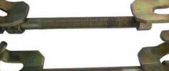
Mandrel
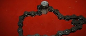
It is not at all necessary to buy a mandrel; you can make it yourself in a few minutes from a scarce material: from the same bearing that needs to be pressed into place. If you are too lazy to bother, you can buy a mandrel or even buy a whole set and use it for your health. Whatever is more acceptable to you, then choose.
We take an old unnecessary bearing that is still capable of rotating. We bring the bearing to the wheel of the sharpening machine and grind the cage a little: if the bearing is turned across the stone, the work will go much faster
There is no need to sharpen the clip, literally a tenth of a millimeter is enough
We cut out the inner ring by welding
For ease of operation, we weld a washer onto the holder
Fitting bearings onto the shaft and into the housing
The inner rings of bearings are often secured to the shafts by means of only an appropriate fit (Fig. 2, a).
Rice. 2. Basic schemes for attaching bearings to a shaft: a – fixed connection using a press fit; b – end washer with screw and locking strip; c – round slotted nut and lock washer; g – retaining ring; d – conical split sleeve and tension round nut and lock washer
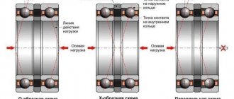
The choice of the type of bearing fit on the shaft and in the housing depends on a number of factors: the type and size of the bearing, its operating conditions, the magnitude, direction and nature of the loads, the accuracy class of the bearing, and the loading of the fixed ring.
The following types of loading of fixed rings are distinguished: local circulation and oscillatory.
The local load is absorbed by a limited area of the raceway and is transferred to a limited area of the housing.
The circulating load is absorbed by the entire circumference of the raceway and is transmitted to the entire supporting surface of the housing. This is observed when the load vector rotates.
The oscillatory load is distributed over a certain area of the non-rotating ring, for example, during a rocking motion.
For a rotating ring that transmits external force, fixed fits should be assigned, for example, in gearboxes, the inner ring of the bearing must be pressed onto the shaft. The outer ring of the bearing, mated to the stationary part of the machine, must have a fit that provides a very small interference or even a small gap, allowing the ring to rotate somewhat relative to its seat during operation, which ensures more uniform wear of the treadmills.
The inner ring of the bearing is seated on the shaft or axle using a hole system, and the outer ring is seated in the housing using a shaft system.
In this regard, the connection of the inner rings of the bearings with the shafts during transitional fits will be virtually motionless with a guaranteed interference. When making a fixed fit, you should very carefully ensure that the connection has a certain interference: loosening the fit leads to the shaft slipping along the inner ring, the temperature of the bearing rises sharply, and it fails. With increased tension, the inner ring of the bearing expands, and the radial clearance between the inner and outer ring decreases. This can lead to jamming of the rolling elements: the bearings heat up and quickly collapse.
Particular care should be taken when seating radial ball bearings. Shaft journals and bored holes in housings with roughly machined seating surfaces should not be allowed for installation.
The roughness of the processing and the geometric shapes of the seats significantly affect the durability of the bearings.
The ovality, taper and runout of the shoulders must be within the tolerances established for the surfaces mating with the bearings.
It should be remembered that the normal operation of the rolling bearings and the entire assembly depends on the accuracy of the shoulders of the shafts and housings, as well as the dimensions of the shaft fillets. During assembly, it is necessary to ensure that the shoulders of the shafts and housings are strictly perpendicular to the shaft axis, and the bearing rings fit tightly to the shoulders over the entire surface.
The dimensions of the shaft and housing shoulders must be such that the ends of the shoulders do not collapse under significant axial load. However, very large shoulders make it difficult to dismantle the bearings, since in this case it is not possible to grasp the bearing ring due to the protruding shoulder. The normal height of the shoulders should be approximately equal to 1/2 the thickness of the inner ring. If it is impossible to provide shoulders of normal height, then special thrust rings are used.
The radius of the shaft fillet should always be slightly smaller than the chamfer radius of the inner ring of the bearing. The same applies to the outer ring.
When designing shafts, grooves are often made instead of fillets. However, they weaken the shaft, causing stress concentration, and therefore they can replace fillets only if the shaft has a significant margin of safety.
In heavily loaded shafts, maximum stresses are concentrated at the shaft seats near the shoulders. In such cases, it is undesirable to make recesses and even fillets. It is recommended to use a smooth conical transition and install a special thrust washer.
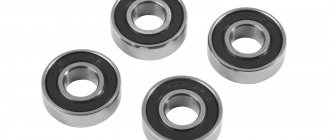
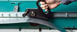
Types of wheel bearing pullers
Study the summary table, which presents several main types of BSC, as well as specific recommended models.
| Type and model | Application | Average price, rub. |
| With 3 legs | Removing parts from axles and shafts, including rear hub ball bearing races. | 2000-3000 |
| With 2 legs | Removing parts from axles and shafts, including rear wheel hub bearings. | 1000-2000 |
| Cup with a set of mandrels | Removing and pressing parts into holes, including steering knuckles and front wheel hub bearings. | 6000-8000 |
What pullers are needed to remove and press in wheel bearings?
For the front and rear wheels, it is recommended to use two types of tools: with three or two legs and a cup puller - this is the minimum set of removable tools for the correct and safe removal and pressing of parts of hub units.
Installation of tapered roller bearings
A design feature of a tapered roller bearing is that the cage protrudes beyond the outer ring by m and n (Fig. 3, a). This should be taken into account when installing parts adjacent to the bearings, for example, spline nuts (Fig. 3, b), or when installing two adjacent bearings (Fig. 3, c).
The adjacent part must be spaced from the end of the outer ring of the tapered roller bearing by b=4...6 mm. To ensure that the cylindrical surfaces of adjacent parts do not touch the separator, the heights h1 and h2 should not exceed the following values: h1=0.1(D–d); h2=0.05(D–d).
Rice. 3. Installation of tapered roller bearings
That is why, in the very common fastening of a tapered bearing with a spline nut (Fig. 3, b), a spacer sleeve 1 is installed between the ends of the inner ring of the bearing and the nut. Approximately half of its length, sleeve 1 fits onto a shaft with a diameter d made for installing the bearing, and with the remaining length it covers groove for the tool to exit when cutting threads.
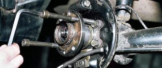
Press-fitting
We heat the seat, position the bearing, place a mandrel on the bearing and use a hammer to drive it to the required depth. You need to hammer in several gentle blows, constantly monitoring so that the bearing does not become distorted.
It is even easier to install a bearing on the shaft: we cut off a piece of a suitable size pipe, heat the bearing, put it on the shaft, place the pipe on the inner race and hammer it in
Adjusting bearing clearances
Adjusting the clearances in bearings has a great influence on their durability and the accuracy of the entire mechanism. There are two types of clearances: radial and axial. During installation and operation of bearings, these gaps change their size.
Before installation, the bearing has a so-called initial gap, after installing the bearing in the unit - a landing gap, and, finally, during operation - a working gap.
The working gap in angular contact and thrust bearings must be such that, on the one hand, the shaft rotates easily, and, on the other hand, the rolling elements are not pinched during thermal elongation of the shaft.
Angular contact and thrust bearings often have to be adjusted during their operation to compensate for clearances resulting from wear. Axial and radial clearances in angular contact and thrust bearings have a certain geometric dependence.
The optimal axial play (clearance) in adjustable bearings depends on many factors: the design and size of the bearings, the temperature of the unit during operation, the rigidity of the supports, the accuracy of the seats; therefore, the amount of axial play is set individually for each node.
It should be taken into account that the absence of clearance, as well as excessively large clearance, leads to rapid wear of the bearings. The exception is the components of precision machine tools, which are mounted on preloaded bearings.
Angular contact bearings and especially tapered roller bearings work better with small axial play.
If the assembly provides high precision boring of the seats, the distance between the bearings is small and there is no fear of pinching the rolling elements, then the lower limits of the axial play should be selected.
If the above conditions in the node are not met, then the limits of the axial play are selected according to table. 1, 2 and 3 taking into account thermal elongation of the shaft.
Table 1. Approximate values of axial play for adjusting tapered roller bearings
| Shaft diameter limits, mm | Bearing series | Limits of axial play, mm |
| Up to 30 | Lightweight | 0,02-0,04 |
| Light wide | 0,03-0,09 | |
| Medium and medium wide | 0,04-0,10 | |
| 30-50 | Lightweight | 0,03-0,07 |
| Light wide | 0,04-0,10 | |
| Medium and medium wide | 0,05-0,12 | |
| 50-80 | Lightweight | 0,04-0,07 |
| Light wide | 0,05-0,12 | |
| Medium and medium wide | 0,06-0,14 | |
| 80-120 | Lightweight | 0,05-0,08 |
| Light wide | 0,06-0,14 | |
| Medium and medium wide | 0,07-0,17 |
Table 2. Approximate values of axial play for adjusting angular contact ball bearings
| Shaft diameter limits, mm | Bearing series | Limits of axial play, mm |
| Up to 30 | Lightweight | 0,02-0,06 |
| Medium to heavy | 0,03-0,09 | |
| 30-50 | Lightweight | 0,03-0,09 |
| Medium to heavy | 0,04-0,10 | |
| 50-80 | Lightweight | 0,04-0,10 |
| Medium to heavy | 0,05-0,12 | |
| 80-120 | Lightweight | 0,05-0,12 |
| Medium to heavy | 0,06-0,15 |
Table 3. Approximate axial play values for adjusting double thrust bearings
| Shaft diameter limits, mm | Double bearing | Limit of axial play, mm |
| Up to 30 | Lightweight | 0,03-0,08 |
| Medium to heavy | 0,05-0,11 | |
| 30-50 | Lightweight | 004-0,10 |
| Medium to heavy | 0,06-0,12 | |
| 50-80 | Lightweight | 0,05-0,12 |
| Medium to heavy | 0,07-0,14 | |
| 80-120 | Lightweight | 0,06-0,15 |
| Medium to heavy | 0,1-0,18 |
Depending on the bearing installation scheme, the axial play is regulated: by gaskets between the housing and the end of the cover (Fig. 4; a, b); threaded rings on the shaft or in the housing; a nut and a special washer (Fig. 4, c), etc.
In this scheme, two bearings are installed in a fixed shaft support (Fig. 4). The inner rings of the bearings of both supports are secured to the shaft. The outer rings of the bearings, located in a fixed support, are secured in the housing. The outer ring of the floating bearing is left free.
Rice. 4. Design of the support assembly with a fixed pair of bearings
In a fixed bearing, radial and axial clearances are minimized by appropriate adjustment, and there is almost no “play” of the shafts. The rigidity of the support increases. In addition, the arrangement of two bearings in a fixed support increases the rigidity of the shaft.
Rice. 5. Scheme for determining the axial play of the shaft
The geometric relationship in a tapered roller bearing between the clearance g along the pressure line (perpendicular to the generatrix of the outer ring raceway), the radial clearance A (perpendicular to the axis of rotation of the bearing) and the axial play S (parallel to the axis of rotation of the bearing) (Fig. 5) is determined by the following formulas:
g=λcosβ;
g=2Ssinβ;
λ=2Stgβ,
where β is the angle between the generatrix of the cone of the outer ring of the bearing and the axis of the bearing.
The amount of axial play S affects only half of the total axial play of the shaft mounted on two tapered roller bearings. The same applies to cases where the shaft is mounted on two or four row tapered roller bearings.
Adjusting the axial play of angular contact ball bearings using gaskets is done as follows: put a set of gaskets on one of the covers, install it in the housing and tighten the bolts until failure.
The second cover (without gaskets) is also put in place; Without pressing the bolts to the end, turn the shaft. Then the cover bolts are tightly clamped, achieving such a position that the shaft rotates tightly (the gap is completely destroyed).
Next, use a feeler gauge to measure the gap between the cover flange and the body. To the value of the gap found with a feeler gauge, add the value of the required axial gap (axial play). This sum of dimensions constitutes the required thickness of the set of spacers to regulate axial play. The axial play is distributed between two bearings.
After measuring the amount of axial play, the cover without gaskets should be removed, a set of gaskets should be selected and installed again with gaskets, the bolts should be tightened until they stop, and the shaft should be rotated by hand.
If the shaft rotates tightly, then you need to add another thin spacer, after which you should check the amount of axial play obtained (using an indicator or feeler gauge):
α–δt=1…2 mm.
For example, short shafts in the absence of significant heating can be secured using two supports. During assembly, to prevent pinching of the rolling elements in radial bearings, a minimum axial clearance a = 0.2...0.3 mm is provided between the bearing cover and the outer ring, and in angular contact bearings, axial adjustment is required by changing the total thickness of the set of gaskets b between the bearing cover flange and its body (Fig. 6).
Rice. 6. Design of the assembly unit for adjusting the gap
After normal thermal conditions are established during operation of the unit, the gap decreases to normal limits or disappears. The value of the initial gap a is usually determined experimentally for each product.
Therefore, this scheme of axial fixation of shafts is used for relatively short shafts and when duplexing (selecting pairs of bearings for installation with preload) thrust ball bearings, which are used in high-speed mechanisms.
The accuracy of bearing adjustment depends largely on the quality of the shims, which must be precisely manufactured (stamped calibrated brass or mild steel).
Adjustment of the axial play of angular contact bearings using threaded rings on the shaft is carried out as follows: the inner ring of the bearing is clamped with a threaded ring until the gap in the bearings is completely eliminated. Then the threaded ring is slightly unscrewed by 1/3 or 1/4 turn, depending on the thread pitch and the required axial clearance, achieving free rotation of the shaft; After this, the threaded ring is locked.
When adjusting the clearance in tapered roller bearings with shims, first clamp the cover without shims until the shaft turns very tightly. When tightening the nuts or screws, the shaft must be rotated several turns to allow the bearing rollers to seat properly.
When the cover is clamped all the way, there is no play in the bearing. By measuring the gap A (Fig. 7, a) between the cover 1 and the body in this position in two or three places and adding to it the required axial movement of the shaft C, we determine the thickness T of the calibrated gasket 2, which must be placed under the cover, i.e. T=A+C.
Rice. 7. Schemes for adjusting the gap in tapered roller bearings: a – with a cover; b – bolt 4 into intermediate cover 3; c – bushing 6 and square 7
When adjusting the clearance in the bearing with bolt 4 and nut 5 (Fig. 7, b), they are first tightened until the shaft turns tightly (this shows that the clearances are selected correctly). Then, based on the thread pitch P, it is determined at what angle φ the screw or nut should be turned back to obtain the required clearance: φ=C/(P•360°) (usually a quarter turn).
Bearing duplexing
Particularly high demands are placed on the operation of a number of bearings (assemblies of precision instruments, aircraft engines, spindles of precision machine tools, etc.).
Shaft vibrations, which occur in the presence of even normal gaps, are unacceptable for these units.
Gaps in the bearing and elastic deformations of its elements under the action of the working load cause axial and radial vibrations of the shaft. The destruction of axial and radial clearances (axial and radial play) in rolling bearings and a significant increase in the rigidity of a set of rolling bearings can be achieved by creating a preload, i.e., applying a preliminary axial load, as a result of which initial elastic deformation occurs and axial clearances in the set disappear .
If a working axial load is then applied to the bearing, the relative movement of its rings will be significantly less than before the preload was created. It should be borne in mind that as the bodies and raceways wear out during operation or long-term testing, the amount of preload will decrease. To maintain the preload, one of the bearing rings is displaced in the axial direction by a device to compensate for wear or deformation of the bearing assembly parts by an amount corresponding to the preload value.
Preload is carried out in various ways. For this purpose, spacer rings h2 are used (Fig. between the inner and outer rings of the bearings, threaded covers and special springs (Fig. 9), which compensate for wear and deformation of the bearing assembly parts.
Rice. 8. Duplexing of bearings: a – determining the size of the inner ring; b – determining the size of the outer ring
Rice. 9. Slotted spring: a – general view; b – axial section (1 – slot, 2 – jumper)
The concept of bearing duplexing includes selecting a set of angular contact ball bearings, modifying the seating surfaces and parts connecting them to select clearances and create interference.
The accuracy of the parts mating with the bearings must correspond to the accuracy of the bearings used in the assembly. For example, the cylindricity and taper of the hole of angular contact ball bearings for the internal grinding spindle of a machine tool, the parallelism of the treadmill and the ends, the radial runout and the parallelism of the bearing ends is no more than 0.5 microns. The accuracy tolerance of the balls in size and shape is no more than 0.125 microns. The spread in the angle of contact of the balls with the raceways is no more than 1-2° for a pair of bearings. These parameters are checked and, based on the test results, pairs of bearings with approximately the same parameters are selected.
When installing this pair of bearings in a duplex manner, it is necessary to ensure the accuracy of the spindle journals and the mounting holes in the housing for the bearings: roundness - 0.5-2 microns, ovality - 1-3 microns, radial runout relative to the axis - 1-2 microns, misalignment of the bearing holes in body – 2 microns at a length of 400 mm, surface roughness – Ra=0.025-0.1 microns. These parameters must be checked before assembly.
Depending on the radial size of the bearings, the amount of axial force that provides preload to the bearings can vary from 30 to 60 kg. When installing duplex bearings, the following recommendations should be followed:
- bearings should be selected in pairs, with approximately the same parameters;
- the maximum radial runout of the inner rings of the bearings and the maximum radial runout of the shaft journal on which the bearing rings are to be mounted must be directed in opposite directions, and the maximum mechanical runout of the bearing rings must be directed in the direction opposite to the maximum mechanical runout of the shaft shoulders;
- The outer rings of the bearings should be installed in the mounting holes of the housing so that the maximum radial runout of all bearings is directed in the same direction.
When repairing specific units with duplex bearings, it is advisable to use the instruction manual and take into account the design features of the mechanism.
Wheel bearing puller drawings.
A 320 mm long stud was also needed and a nut was welded to it. I also pressed the ball from the bearing into the center of the stud.
According to the drawings, they made these:
Cup with mate.
Also two washers measuring 74 mm and 62 mm.
This is what the entire set of tools for pressing out wheel bearings looks like.
In this video, the author shows in detail a wheel bearing puller.
I recently shared with subscribers about refining a homemade hydraulic press
.
And also about how it was used to press out and press in the Ford hub. There were questions from subscribers and just guests about how to properly press the hub without damaging the bearing. I'm telling you. There are three options for pressing the hub into the fist: Method 1
: The simplest is to bluntly press the hub into the fist with a press. In this case, all the hydraulic pressure from the inner race of the bearing passes through the balls to the outer race. In this case, 99% of cases end in damage to the balls and cages and the hub will begin to rustle after 2-3 thousand km. This is usually done by those who press out the hub in this way.
For us, the creative and technically savvy, the third option is closer to the body. I’ll make a reservation right away. The idea is not mine. Somewhere, I saw something similar on the Internet. And I’ll upset some followers - you can’t do without turning. So, we need to make three parts. Two identical parts No. 1 of this plan
Installation of needle bearings
The assembly of bearing assemblies, in the supports of which free needle rollers are used, is carried out using auxiliary bushings. The diameter of the outer surface of such bushings should be 0.2-0.3 mm less than the diameter of the journal of the shaft with a raceway for needle rollers.
A layer of grease (used to lubricate the bearing assembly) is applied to the surface of the raceway in the housing hole, onto which needles are “sticked” in one or more rows. An auxiliary sleeve is inserted into the resulting hole; Thanks to the reduced diameter (against the shaft diameter) of the outer surface, the bushing easily fits into the hole between the needles. The mounted shaft is pressed tightly against the end of the auxiliary bushing and, together with the auxiliary bushing, is pushed into the hole (Fig. 10).
Rice. 10. Installation of an incomplete needle bearing
During installation of the shaft, the auxiliary bushing holds the needles on the surface of the hole and does not allow them to fall out of the hole, and the mounted shaft with its chamfer presses the needles to the surface of the raceway in the housing.
Complete needle bearings (with outer and inner rings), as well as with a thin-walled stamped outer ring, are mounted in the same ways that are applicable for installing other types of bearings with massive rings. In this case, bearings with a stamped outer ring should be seated into the housing only using a manual or mechanical press, since even light local blows of a hammer through a copper drift on a thin-walled ring cause its deformation and damage. It is most advisable to use special devices (Fig. 11).
Rice. 11. Device for mounting an incomplete needle bearing with a thin-walled stamped outer ring
Cups for bearings
To accommodate shaft supports consisting of several bearings, cups are used (Fig. 12). Glasses are usually made of cast iron grade SCh15 and steel, which are used in a cast iron or silumin body under significant loads.
Rice. 12. Designs of cups for bearings: a – for universal assembly; b – for two tapered bearings (inside the cup); c – for two tapered bearings (one outside and one inside); g – for two tapered bearings with collars
The wall thickness of the cups δ, mm, is taken depending on the diameter D of the hole in the cup for the bearing. The cups for the bevel gear shaft bearings (Fig. 12, a) are moved during assembly to adjust the axial position of the bevel gear. To do this, use the fit of the glass in the H7/js6 housing. Other glasses, after they are installed in the body, remain motionless. Then plantings of type H7/k6 or H7/m6 are used.
Bearing caps and seals
The axial position of the shaft in the housing is determined using end caps. The end caps must be strong enough to withstand the axial loads transmitted by the shafts through the outer bearing rings.
Bearing caps are made of SCh15 cast iron. There are covers that are blind and have holes for the passage of shafts (Fig. 13). The covers are manufactured with or without a centering ledge. The centering lug usually contacts the outer race of the bearing to fix the position of the shaft in the housing. The outer diameter of the protrusion is equal to the diameter of the bore for the bearing according to the h9 fit, and the inner diameter corresponds to the size t in the cup. The thickness and outer diameter of the flange, the diameter on which the holes are located, and their number are determined in the same way as for a glass.
Rice. 13. Shaft seals placed in the covers: a – lip seal; b – slot ( l =0.2…0.4; t=4.5…6; r=1.2…2); c – centrifugal; d – labyrinthine ( l =0.2…0.4; f1=1…2; f2=1.5…3)
If the cover does not contact the bearing, then it can be made without a centering belt (flat). If the cover is made with a hole for the passage of the shaft, then it differs in that it usually provides a place for installing a seal, which protects the bearing from dirt and from leakage of lubricant (Fig. 13, a). The presence of a seal and bearing mounting parts on the shaft determines the configuration of the outer and inner end surface of the cover in the axial section (Fig. 13).
Since slot seals do not reliably protect bearings from dust and dirt, they are used for rolling bearings of machines operating in a clean and dry air environment. Labyrinth seals (Fig. 13, c) are the most reliable, especially at high shaft speeds. Seals based on the action of centrifugal force (Fig. 13; a, c, d) are used as external and internal ones. In critical cases, combined seals (c) are used. Rubber lip seals for shafts are given in table. 4.
Table 4. Rubber lip seals for shafts
| Reinforced rubber cuff, mm | d | D | h1 | h2 |
| 20; 21; 22 | 40 | |||
| 24 | 41 | |||
| 25 | 42 | |||
| 26 | 45 | |||
| 30; 32 | 52 | |||
| 35; 36; 38 | 58 | 10 | 14 | |
| 40 | 60 | |||
| 42 | 62 | |||
| 45 | 65 | |||
| 48; 50 | 70 | |||
| 52 | 75 |
To prevent lubricant from leaking out of the gearbox housing or being carried away in the form of oil mist and splashes, various sealing materials and devices are used. The connectors of composite housings are sealed with special ointments applied to the connector planes before assembling the housing. In flange connections, when the position of the flange does not determine the axial clearance in the bearing assembly, soft sheet gasket materials can also be used.
Currently, seals in the form of rubber O-rings are widely used to seal flange connections (Fig. 14, a).
To seal joints of the flange-housing type with a centering collar, rings are installed in the groove (Fig. 14, b), in the end (Fig. 14, c) and in the chamfer (Fig. 14, d). Installation of rings in the groove takes up more space in the axial direction, but is convenient when combined with adjusting shims between the flange and the body for axial clearance, since in this case the change in the thickness of the shims is not associated with deformation of the ring section that seals along the seating surface. The dimensions of the mounting locations for rubber O-rings are given in table. 5. The same rings can be used for non-centered flat joints (not necessarily circular). To do this, a groove must be made on one of the parts to be connected. An example of a circular seal is shown in Fig. 14, bldg.
Table 5. Dimensions of cross-sections of round rings and installation locations for them
| Dimensions | Ring diameter, d, mm | |||
| 2,5 | 3,0 | 3,6 | 4,6 | |
| D | 24-54 | 25-100 | 28-205 | 36-260 |
| b | 3,6 | 4,0 | 4,7 | 5,6 |
| h | 1,85 | 2,35 | 2,8 | 3,7 |
| With | 2,0 | 2,0 | 2,5 | 2,5 |
| A | 3,5 | 4,5 | 5,0 | 6,0 |
| e | 1,85 | 2,2 | 2,6 | 3,3 |
| M | 3,3 | 4,2 | 5,0 | 7,2 |
Rice. 14. O-ring seal