Orbitalum Tools is your reliable partner in the field of pipe cutting and facing, as well as automatic orbital welding of industrial pipelines.
Types of welding - Gas shielded arc welding
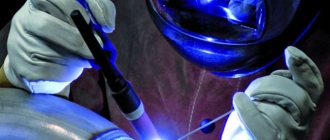
Gas shielded welding is one of the most common fusion welding methods. Compared to other methods, it has a number of advantages, the main ones of which are: the ability to visually, including remotely, monitor the welding process; wide range of operating parameters of welding mode in any spatial positions; the possibility of mechanization and automation of the process, including the use of robotics; highly effective protection of molten metal; the ability to weld metals of different thicknesses ranging from tenths to tens of millimeters.
The essence of the method
Welding of workpieces in a shielding gas environment is one of the subtypes of arc bonding, but here argon, nitrogen, oxygen, etc. are supplied to the melting point. If there is a need to integrate low-carbon or alloy steel, 1-5% oxygen is added to the gas. Such proportions reduce the critical tension, which protects against the formation of pores and improves the quality of adhesion.
For production with a melting rod, argon and 10-20% carbon dioxide are mixed. This gives the same indicators as in the previous case, however, it adds constancy to the arc and protects the area from drafts. The technique itself is popular mainly in the processing of thin sheets of metal.
During deep smelting, CO2 and 20% O are used. The mixture is endowed with increased oxidizing properties, gives a good shape, and protects the slabs from porosity. Similar indicators are typical for other compounds, but each procedure has an individual approach, which will depend on the situation, the thickness of the object and other parameters.
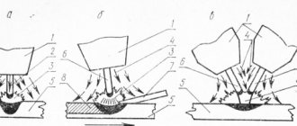
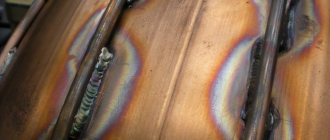
Scheme of gas-shielded arc welding
Despite the highest results, the joining plane must be carefully processed using the following techniques:
- alignment;
- rust removal;
- removal of nicks;
- heating.
If the preparatory manipulations are performed incorrectly, this will lead to weld defects.
Wire for semi-automatic welding
Semi-automatic welding is performed with a special wire. Its choice depends on several factors.
- Material to be welded (Black, non-ferrous, alloys)
- Thickness of welded metal
- The principle of protecting the weld pool
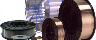
Types of welding wire for semi-automatic welding
- Copper-plated
- Powder
- For stainless steel
- Aluminum
Each type is used in different situations.
Copper-plated welding wire for semi-automatic machines is most often used. It is used during the production and construction of metal structures, aircraft and shipbuilding, as well as in the automotive industry.
Flux-cored wire is used for semi-automatic welding without shielding gas. The powder that is in the wire and releases the necessary protective gases, but subsequently forms a slag crust.
Stainless steel wire is used for welding stainless steels.
Aluminum welding wire is excellent for welding Aluminum and Aluminum alloys.
In addition, the welding wire may differ in diameter. So, there are welding wires of 0.6 mm, 0.8, 1 mm, 1.2 mm…. 2mm _ The choice of welding wire diameter directly depends on the thickness of the metal being welded . And according to the thickness of the welding wire, a suitable copper tip is selected, which supplies voltage to the wire to excite the welding arc.
Welding technology
Gas-shielded arc welding involves the use of two approaches: non-consumable and consumable pins. The first type makes a weld by melting the corners of the alloy. In the second case, the remelted rod plays the role of the main substance for integration. To ensure optimal preservation of the environment, several variations are used:
- Inert - have no color and odor, and inertness is determined by the presence of a dense electron shell in the atoms. These types include helium, argon and others.
- Active - react with the workpiece and dissolve in it. This category includes carbon dioxide, nitrogen, hydrogen and others.
- Combined impurities. This includes combinations of the previous points. Automatic welding in an environment of real shielding gases is needed to improve technical attributes and form a high-quality seam.
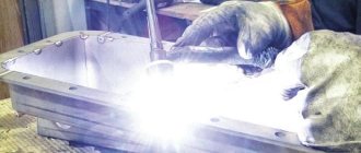
Shielded gas welding technology
The choice will differ from the chemical composition of the metal, the economy of the procedure, the bonding properties and other nuances.
It is also allowed to use electric arc equipment for manipulations.
Inert gaseous impurities will increase the stability of the arc and make it possible to carry out deeper melting. The mixture is fed into the dynamic area by several flows: central (parallel to the rod), lateral (on the side, separate from the rod), a pair of concentric jets, and into a movable nozzle, which is mounted above the working medium. Arc welding in any shielding gas creates acceptable thermal parameters that have a positive effect on the model, size and quality of the seam.
Specialized nozzles are used to supply the gas stream, but in some circumstances objects are placed in transparent chambers that are installed above the joint. This technique is used quite rarely, and mainly for fastening large-sized components.
Features of welding different metals and alloys
Welding steels
Welding of low-carbon and low-alloy steels in inert gas is rarely used, since these steels are well welded under submerged arc and in carbon dioxide.
High technological properties when welding steels are ensured by adding up to 1-5% oxygen to argon. Oxygen helps to increase the density of the weld metal, improve fusion, reduce undercuts and increase the productivity of the welding process.
For welding low-carbon and low-alloy steels, argon with the addition of 10-20% carbon dioxide can also be used. Carbon dioxide helps eliminate porosity in seams and improve seam formation.
High-alloy steels are successfully welded in inert gases and their mixtures. This ensures high arc stability and minimal waste of alloying elements. The chemical composition of the weld metal is controlled by using wire of the desired composition. Steels containing elements with high oxygen activity (aluminum, titanium, zirconium, etc.) are welded in an inert gas environment. Approximate modes of automatic and semi-automatic welding of butt joints with a thickness of 4-10 mm at direct current are given in Table. 2.11.
Welding of copper and copper alloys
Copper (Welding technology for copper and its alloys) can be welded well in argon, helium and nitrogen, as well as in a mixture of argon with helium and nitrogen. In order to save argon and increase productivity, it is advisable to use a mixture of argon and nitrogen (70-80% argon and 30-20% nitrogen). Nitrogen helps to increase the depth of copper penetration.
Due to the high thermal conductivity of copper, in order to obtain reliable penetration at the beginning of welding and good fusion along the edges, the parts are heated to 470-770 K. When welding in argon, heating is necessary when the copper thickness is more than 4 mm, and in nitrogen - more than 8 mm. The amount of welding current is selected based on the diameter of the tungsten electrode, the composition of the protective mixture and the type of current. In this case, welding can be performed on both alternating and direct current of reverse polarity.
When welding brass, bronze and copper-nickel alloys, it is preferable to use a tungsten electrode. In this case, the evaporation of zinc and tin will be significantly less than when welding with a consumable electrode. The filler metal, and sometimes the edges to be welded, are cleaned by etching. For this, a solution consisting of 75 cm3/l HNO3, 100 cm3/l H2SO4 and 1 cm3/l HCl is used.
Some modes for welding copper butt joints in the lower position are given in table. 2.12.
Welding of aluminum and magnesium alloys
These alloys have high values of electrical conductivity, thermal conductivity, and latent heat of fusion. The difficulty in welding these alloys lies in the presence of a refractory oxide film on their surface, which prevents the fusion of the metal of the weld pool with the base metal and, in addition, remains in the weld in the form of non-metallic inclusions. When welding with reverse polarity current, cathodic cleaning of the surfaces being welded occurs in the area affected by the arc. However, only a relatively thin oxide film can be destroyed by the discharge current. A thick film of aluminum oxide must be removed mechanically or chemically before welding. It is especially important to remove the oxide film from the surface of small diameter electrode wire (made of aluminum and magnesium alloys). This is explained by the fact that moisture is well sorbed on the surface of the oxide film, which, dissociating in the arc, leads to saturation of the weld metal with hydrogen and an increase in its porosity. The nature of porosity formation also depends on the chemical composition of the alloy. When welding aluminum-magnesium alloys, the oxide film is thicker than that of pure aluminum and retains more moisture.
Thermally hardenable alloys of the Al-Mg-Si system (grades AB, AKB, AKB) have an increased tendency to form hot cracks, which is determined by the presence of low-melting eutectics, which expand the temperature range of the solid-liquid state. To reduce the susceptibility of these alloys to hot cracks, it is advisable to use additives containing 4-6% Si.
The quality of welded joints is influenced by the choice of structural elements for cutting edges, which are defined by GOST 23949-80.
The accumulated experience in welding structures made of aluminum alloys has made it possible to develop modes that ensure high quality welded joints (Tables 2.13 and 2.14).
Modes
For these operations, semi-automatic class inverter units are often used. With their support, electricity and supply voltage are adjusted. These stations also serve as a basic power source, and their power and regulation options vary depending on the model. If there is a need to carry out standard activities (without handling thick and unpopular alloys), you can choose the simplest equipment.
Carbon gas welding modes
Automated gas shielded arc welding can vary in many quantities, most of which are determined by the following positions: 1st wire radius, 2nd wire diameter, 3rd electrical power, 4th voltage, 5th contact feed speed, 6 -e gas consumption. And it all looks like this:
- 15cm, 0.8mm, 120A, 19V, 150m/h, 6 units/min;
- 7mm, 1mm, 150A, 20V, 200m/h, 7 units/min;
- 2mm, 1.2mm, 170A, 21V, 250m/h, 10 units/minutes;
- 3mm, 1.4mm, 200A, 22V, 490m/h, 12 units/min;
- 4-5mm, 0.16cm, 250A, 25V, 680m/h, 14 units/minutes;
- more than 0.6cm, 1.6mm, 300A, 30V, 700m/h, 16 units/min.
These characteristics are standard and are calculated for processes with carbon dioxide.
Features of the technique
One of the subtypes of arc joining of metal products and workpieces is gas-shielded arc welding. GOST regulates the process during which gas is supplied to the melting point. This can be argon, oxygen, nitrogen or other varieties. There are certain features of such a process.
Every welder knows that the quality of the weld depends not only on the skills of the welder, but also on the conditions at the melting point. Ideally, only the electrode and filler materials should be present here. If other elements get here, they can have a negative effect on welding. Because of this, the soldering area will not be strong enough.
The technology of manual gas-shielded arc welding dates back to 1920. The use of such substances allows you to make seams without slag. They are characterized by high purity and are not covered with microcracks. This method is actively used in industry to create various elements from metal.
Special proportions of protective gases allow you to relieve stress in the melt zone. There are no pores here, which significantly improves the quality of adhesion. The seam becomes stronger.
In industrial conditions, rods mixed with argon and carbon dioxide are used during welding. Thanks to this combination, the arc becomes constant, protecting the melt zone from drafts. This allows you to join thin sheets of metal.
If deep smelting is required, carbon dioxide and oxygen are mixed. This composition has oxidizing properties and protects the seam from porosity. There are many techniques that involve the use of different gases during welding. The choice depends on the specifics of this process.
Manual method and chamber welding
Semi-automatic units, accompanied by the use of a protective environment, are divided into two approaches: local and general types. In most cases, the first version is used, where the protective substance flows directly from the nozzle. This technique makes it possible to cook any product, however, the result may not always be at a satisfactory level. Getting air into the melting zone will greatly reduce the performance of the seam, and the larger the item, the higher the chances of getting a poor quality solder.
Therefore, for large-sized ones, it is recommended to operate cameras with adjustable atmosphere inside. It goes like this:
- all air is pumped out of the cavity to a vacuum state;
- then the required gas is pumped in;
- cooking is carried out with remote control.
Welding chamber
There are other methods of manual arc welding in shielding gases: a certain space is filled with the appropriate element, and the specialist performs all actions in a spacesuit with an individual breathing system.
These are quite complex acts that require training and skills. But this gives an absolute guarantee that the spike will be in reliable defense. And this is an important requirement for the production of complex workpieces. As for electrodes, you can use both consumable and non-consumable models.
Welding process
Electricity is supplied to the electrode from the welding current source. When the electrode comes into contact with the metal being welded, an electric arc is formed, which melts the product and the electrode, resulting in a weld pool. The electrode material, entering this bath, fuses the edges of the metal that needs to be welded, and the coating provides protection in the area where the seam is formed and forms a protective layer at the end of the welding process.
Consumable electrode welding diagram
Preparation of edges and their assembly for welding
Preparatory actions are carried out in the same way in all options. The edge cutting pattern must contain the correct geometric parameters and comply with GOST or other technical rules. With mechanical welding, it is possible to completely boil the alloy without separating the edges or leaving a gap between them. If there is some indentation or cutting edges, welding can be carried out, but the thickness of the object should be no more than 11 mm. There are ways to increase the productivity of the automatic welding acceptance process, and for this it is necessary to cut the side corners without a slope.
Download GOST 14771-76
During welding, the metal shrinks, which affects the correctness of the gap. To avoid difficulties, a hinged attachment is performed with a certain opening angle of the edges, which will depend on the size of the object.
Prepared edge
When working with carbon dioxide protection, the entire surface has to be cleared of slag and drops of dirt. To reduce future contamination that may form during manipulation, the surface is treated with special liquids. There is no need to wait for the aerosol to dry completely. Subsequent assembly is carried out using standard spare parts: wedges, brackets, tacks, etc. You should also inspect the structure before starting.
Semi-automatic welding technique
Semi-automatic welding of butt joints
Parts with a thickness of no more than 0.8-4 mm are welded without cutting edges, fixed in assembly and welding fixtures. Thin metal is welded on linings made of the same metal as the product or on copper and stainless steel removable linings. Metal with a thickness of over 4 mm can be welded either on weight or on supports.
When welding with a semi-automatic machine, thin metal is much easier to weld when in a vertical position. Welding is carried out at an angle backwards, and the torch is moved in the direction from top to bottom. At the same time, the welder can clearly see the formation of the seam and the welding zone.
For welding thick metal, it is better to use gases that increase the thermal power of the arc - helium or mixtures of helium and argon. In this case, you need to monitor the position of the burner relative to the seam. A slight deviation of the torch from the vertical can lead to non-fusion of the edges of the welded parts.
Semi-automatic welding of corner and T-joints
It is preferable to carry out corner welding when the welded parts are arranged in a boat. In this case, the output of electrode wire is increased by 10-15% compared to welding butt seams in the lower position.
Welding fillet and tee welds is complicated by poor observation of weld formation due to the torch nozzle. Distance e = 0, with a metal thickness of up to 5 mm, and e = 0.8-1.5 with a metal thickness of over 5 mm.
Welding lap joints
Welding of lap joints with a metal thickness of less than 1.5 mm is performed on a copper or steel backing in one pass.
Welding of parts with a thickness of more than 1.5 mm is carried out on weight in several passes.
Semi-automatic welding of horizontal seams
Welding of horizontal seams is carried out at a “forward angle” without transverse oscillatory movements of the torch. Metal with a thickness of more than 6 mm is welded in several passes.
Welding of parts up to 3 mm is carried out at a right angle to the torch axis relative to the welded parts, without cutting the edges.
Welding parts over 3 mm in a horizontal position is welded with the top edge grooved, and the torch is tilted relative to the top part at an angle of approximately 70º.
Welding vertical seams
It is recommended to weld vertical seams with wire with a diameter of 0.8-1.2 mm with free formation of the seam. You can use the technique of frequent short circuits or use pulsed arc sources. It is better to weld parts up to 4 mm thick using a top-down method without oscillatory movements. If you plan to weld with a one-sided seam, it is better to assemble parts with a gap.
Welding ceiling seams
Ceiling seams thicker than 6 mm are best welded in several passes. It is recommended to semi-automatically weld aluminum and its alloys at a forward angle, and weld steel, copper, titanium and other metals at a backward angle.
Advantages and weaknesses of the process
The positive aspects include the following points:
- unlike other methods, the nature of the seam is obtained with higher characteristics;
- most elements are not expensive, however, this does not prevent them from providing high-quality protection;
- An experienced welder will not have any problems mastering this technology, so large-scale production can easily change the specifics of the maneuvers;
- welding of both thin and thick sheets can be carried out in a protective environment;
- this technique shows high performance indicators;
- the technique is excellent for procedures with aluminum, non-ferrous metals and other types that are resistant to corrosion;
- This approach is easy to modernize, it can be easily transferred to an automatic procedure, and can be adapted to any conditions.
The disadvantages of gas shielded welding are as follows:
- When welding in an open space, care should be taken to ensure good sealing of the chamber. Otherwise, there is a high probability of weathering of gaseous impurities;
- cooking in a closed space must be accompanied by high-quality ventilation functionality;
- Some types of gases, such as Argon, are expensive.
Otherwise, the technology is quite successful and does not have any significant drawbacks.
Peculiarities
First, about fully mechanized welding, this is an automated process of joining parts, when the operator only sets up the equipment and monitors its operation. The device itself ignites and maintains the arc, guides it along the seam, while supplying filler wire, flux or shielding gas.
In partially mechanized welding, consumables are supplied automatically, and the welder is responsible for the geometry of the weld. It moves the burner at the desired speed in the given direction. Full or partial mechanization processes are also regulated by welding technology standards.
What gases are used
Shielding gases create the environment for arc welding, and the inert and chemical groups are separated. The first category seems to be the most popular and includes "Ar", "He" and other combinations thereof. Their main task is to displace oxygen from the area of thermal influence. It should be noted that these variations of substances do not react with iron and do not dissolve in it.
The use of this class is necessary for soldering the most popular alloys: titanium, aluminum and others. If the steel has increased resistance to temperature and does not melt well, it is wise to use a non-consumable electrode.
Gases used for welding
Active gases also enjoy a certain popularity, because this category includes inexpensive varieties: hydrogen, nitrogen, oxygen.
But carbon dioxide is most often used because it is the most profitable option.
Description of each version:
- Argon is a variation of the protective inert gas for welding. Has no tendency to ignite and is not explosive. Provides good protection for bathtubs.
- Helium is supplied in special cylinders, the pressure of which reaches 150 at. It has a low liquefaction temperature of -269 degrees.
- Carbon dioxide is non-toxic, colorless and odorless. It is extracted by extraction from flue gases and using special equipment.
- Oxygen – promotes combustion. O is obtained from the atmosphere by cooling. There are several varieties that differ in percentage.
- Hydrogen is explosive when in contact with air, so safety rules must be strictly followed when handling it. It is also colorless and odorless and helps with combustion.
Shielding gases
Noble gases
Inert monatomic gases are almost completely neutral with respect to all metals being welded. Inert gases are used for welding chemically active metals and alloys, as well as in all cases where it is necessary to obtain welds that are homogeneous in composition with the base and filler metals.
In welding production, argon used is supplied in gaseous (Table 2.1) and liquid states. Argon gas is released, stored and transported in steel cylinders (according to GOST 949-73) or tank trucks under a pressure of 15±0.5 or 20±1.0 MPa at 293 K.
When argon is supplied in cylinders (according to GOST 949-73) with a capacity of 40 dm3, the gas volume in the cylinder is 6.2 m3 (at a nominal pressure of 15 MPa and 293 K).
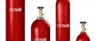
Helium for welding is supplied in accordance with TU 51-689—75 in three grades: grades A, B and C (Table 2.2). Helium is transported and stored in steel cylinders with a capacity of 40 dm3 in a gaseous state at a pressure of 15 MPa or in a liquefied state at a pressure of up to 0.2 MPa. The cost of helium is much higher than argon, so it is used mainly for welding chemically pure and active metals and alloys. The use of helium ensures a greater penetration depth (due to the high ionization potential), so it is sometimes used in cases where it is required to enhance the penetration ability of the arc or obtain a special weld shape.
Active protective gases
Carbon dioxide is widely used as an active shielding gas in welding. Active gases may also include nitrogen and hydrogen, used in some welding processes as a component of the shielding gas.
In the welding industry, nitrogen is sometimes used for welding copper and its alloys, in relation to which nitrogen is an inert gas. In relation to most other metals, nitrogen is an active gas, often harmful, and they strive to limit its concentration in the melting zone.
Hydrogen
in welding production they are used quite rarely for hydrogen atomic welding and arc welding in a mixture (Ar + H2 up to 12%). Hydrogen is only used in specialized welding applications because it plays an important role in metallurgical welding processes. Due to the possibility of the formation of an explosive mixture between hydrogen and air, when working with it, safety requirements must be strictly observed.
Gas mixtures
In some cases, to expand the technological capabilities of arc welding, it is advisable to use mixtures of argon and helium. The addition of helium helps to increase the penetrating ability of the arc.
1. Mixture of Ar+(10÷30% N2). The addition of N2 to argon also helps to increase the penetrating ability of the arc. This mixture is used when welding copper and some grades of austenitic stainless steel.
2. Mixture of Ar+(1÷5% O2). The admixture of oxygen to argon lowers the critical current at which droplet transfer of metal turns into jet transfer, which makes it possible to slightly increase welding productivity and reduce metal spattering. Argon-oxygen mixture is used for welding low-carbon and alloy steel.
3. Mixture of Ar+(10÷20% CO2). Carbon dioxide when welding low-carbon and low-alloy steel helps eliminate porosity in welds. The addition of CO2 to argon increases arc stability and improves weld formation when welding thin-sheet steel.
4. A triple mixture of 75% Ar - 20% CO2 - 5% O2 ensures high stability of the arc with a consumable electrode when welding steel, minimal metal spattering, good weld formation, and no porosity.
In the absence of ready-made gas mixtures, mixing of gases can be carried out at the welding station. The composition of the mixture supplied to the burner is regulated by changing the flow rate of gases included in the mixture. The flow rate of each gas is regulated by a separate reducer and measured with an RS-3 type rotameter.
Gas protection methods
In relation to the electrode, the protective gas can be supplied centrally or laterally. Protection of the weld pool by gas flowing from the torch is usually called jet protection. Jet protection is the most common method of local protection during welding. The quality of jet protection depends on the design and size of the nozzle, the flow rate of shielding gas and the distance from the nozzle end to the surface of the metal being welded. The best protection of the molten metal is provided by the laminar nature of the gas flow from the burner nozzle.
Approximate data for calculating argon consumption per 1 m of weld when welding under normal conditions without drift flows are given in table. 2.3 and 2.4.
When normalizing gas consumption, 15% of its quantity should be reserved for purging the gas pipeline before starting work, for the unused remainder in the cylinder (0.3-0.4 MPa), for welding control samples and for welding defects in welds.
It is recommended to determine helium consumption according to the standards for argon consumption, introducing a correction factor of 1.3.
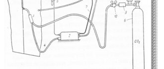
In carbon dioxide
This is the cheapest system, which is why it is in great demand. However, the intense heat in the active region breaks down matter into three gases: "CO2", "CO" and "O". To protect the surface from oxidation, silicon and manganese are added to the wire. But this also causes some inconvenience: when reacting with each other, both substances form slag, which subsequently floats to the surface. It is very easy to remove and does not affect the protective performance in any way. Also, before performing the operation, you should remove all the water from the cylinder (to do this, just turn it over). And these actions should be carried out periodically. If you miss this moment, you may end up with a porous seam.
Welding in carbon dioxide
Pros and cons of the method
The advantages of this welding method have always been considered:
- ease of operation and low price of equipment for the welding process;
- the ability to weld a large number of types of metals with a wide range of choice of electrode material;
- ability to perform welding work in hard-to-reach places;
- Suitable for welding in any spatial position.
Among the disadvantages it is worth highlighting:
- the process releases a large amount of substances that are harmful both to the welder himself and to others;
- The quality of the weld largely depends on the experience and qualifications of the welder;
- the speed of work is often lower than with other methods;
- When welding with direct current, magnetic fields greatly influence the deflection of the arc , which complicates the process.
In a nitrogen environment
Needed for connecting copper blanks or stainless steel parts. This specificity is observed because this gas does not react with these alloys. Graphite or carbon contacts are also required for welding. Tungsten ones cause them to overspend, which makes manipulation very inconvenient.
As for setting up the equipment, it varies depending on the complexity. More often they look like this: current voltage 150-500 A, arc 22-30 V, gas flow up to 10 liters per minute. The appearance of the units has no distinctive features, with the exception of a special clamp for the carbon electrode.
Welding in nitrogen environment
Preparation for welding
To correctly perform the procedure for joining metal workpieces, you need to understand the essence of gas-shielded arc welding. Welding requires proper preparation. This procedure is always the same, regardless of welding technology. First, the edges are given the correct geometry. This is determined by GOST 14771-76.
Mechanized gas shielded arc welding is used to completely weld the alloy, allowing the edges of the workpiece to be completely joined. There is no gap left between them. If there is a certain indentation, edge cutting, welding can be carried out for a workpiece whose thickness does not exceed 11 mm.
To increase productivity, the automatic welding process involves cutting the edges of workpieces without slopes.
After welding in carbon dioxide, you will need to clean the entire plane of the seam from dirt and slag. To make contamination less significant, surfaces are treated with special compounds. Most often these are aerosols that are sprayed onto metal. There is no need to wait for it to dry.
During subsequent assembly, standard spare parts are used, for example, wedges, tacks, staples, etc. The structure requires a thorough inspection before starting work.
Equipment
When welding in a protective environment, standard power sources that have a voltage regulation function are used. There are also automatic wire supply mechanisms and specialized gas units in the form of hoses and cylinders. The procedure itself is carried out with a constant supply of high-frequency electricity.
The main options that require careful attention are the current regulator, which ensures stable arc burning, and the speed of wire movement.
And all this must work as a single mechanism. Modes can differ greatly from each other, even if welding takes place with the same type of iron.
Units:
- PDG-502. Designed for welding in carbon dioxide, it is very reliable and shows high performance. Can be used from networks of 220 and 380 V, and the electricity regulation limits are 100-500 A.
- "Impulse 3A". Necessary for working with aluminum parts, but it has lower functions than the previous device. It can also be used for welding ferrous metals and making ceiling joints.
- "URS 62a". Excellent for field work, used primarily for bonding aluminum. The necessary power is taken from a 380 V network. A special feature is that the device is capable of processing titanium.
Impulse-3 device
There are many more varieties, each of which has its own advantages and disadvantages. It’s not difficult to guess that each machine is designed for a limited range of cooking.
Advantages and disadvantages of the method
The wide range of shielding gases used makes this method widely used both in relation to the metals being welded and their thicknesses (from 0.1 mm to tens of millimeters). The main advantages of the welding method under consideration are the following:
- high quality of welded joints on a variety of metals and their alloys of different thicknesses, especially when welding in inert gases due to the low waste of alloying elements;
- possibility of welding in various spatial positions;
- absence of operations for filling and cleaning flux and removing slag;
- the ability to monitor the formation of a seam, which is especially important for mechanized welding;
- high productivity and ease of mechanization and automation of the process;
- low cost when using active protective gases.
The disadvantages of this method include: the need to use protective measures against light and thermal radiation from the arc; the possibility of gas protection being violated when the gas jet is blown away by air movement or when the nozzle is splashed; metal surface for spattering, in which the splashes are firmly connected to the surfaces of the seam and the product; the presence of gas equipment and, in some cases, the need for water cooling of burners.
Protection options
Any welding work carries an increased degree of danger, so every worker must take care of the protection of the skin, eyes and respiratory organs. Even short-term overcooking in your own garage should be carried out with the following kit:
- mask;
- heat-resistant gloves;
- respirator.
Safety precautions
This is the only way to perform a high-quality operation without compromising your own health.
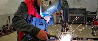
Welding process
Gas shielded arc welding is an effective technique. But in order to achieve this, the master must fulfill all the requirements set forth by the standards for this process. This technique is somewhat different from other techniques, which the master must take into account.
First, the metal is prepared for the welding process. When using this technology, this procedure has less impact on the result, but it must be carried out. Next, the equipment is configured in accordance with the welding parameters. The thickness and type of material are taken into account.
When the equipment is ready, the arc is ignited. At the same time, the burner flame is ignited. Some types of welding require preheating of the workpiece. To do this, first turn on the burner, with the help of which the metal is pre-treated.
When a weld pool begins to form around the arc, the wire begins to feed. For this purpose, the equipment is equipped with a special feeding device. It delivers the wire to the melt zone at a certain speed. If you need to make a long seam, this is convenient, since you don’t have to break the arc. For this, a non-fusible electrode is used, which maintains the arc for a long time.
If welding occurs using direct current, its polarity must be reversed. This reduces the likelihood of spattering, but increases metal consumption. The deposition rate when using this technique is noticeably reduced. With straight polarity it increases by 1.5 times.
It is advisable to conduct the bath from left to right (if the master is right-handed). This will show the process of seam formation. Also, all actions must be performed towards yourself. The seam is created simply; the craftsman only needs to move the machine smoothly at a constant speed.
The arc breaks away from the workpiece in the opposite direction to the welding motion. In some cases, after such manipulation, additional heating may be required.