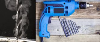
In mechanical engineering, a metal drill is the second most frequently used tool after a cutter, and in the household it confidently shares leadership with a hacksaw and a cutting wheel. Structurally, a drill is a long cylindrical metal rod with two cutting edges at the end and spiral grooves for removing chips. The principle of cutting metal and forming a hole for all types of this tool is almost the same, therefore the main classification of metal drills is based on design features (type of shank, spiral profile, type of cutting edge, etc.). It is quite difficult to determine all the necessary characteristics of a drill by appearance, since the markings that are engraved on the metal of the shank contain information only about the diameter of the tool, the material of manufacture and the manufacturer. Therefore, in order to choose a drill for processing hard, brittle or tough metals and alloys, you need to use the manufacturers’ catalogs. Long-term and short-term storage of drills must be carried out according to certain rules, since tool and high-speed steels are prone to corrosion, and sharpened edges are easily damaged when hitting metal.
Drill design and geometry
Any drill, regardless of its purpose and design features, consists of two main components: the shank and the working part. The first serves to transfer rotation to the tool from the drive or to fix it in a stationary state (on lathes). The working part consists of a number of elements that directly support the drilling process. The geometry of the drill depends on the characteristics of the drilling for which it is intended, as well as the material of the workpiece being processed (various metals, wood, plastics, composites, ceramics).
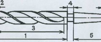
As an example, we take one of the most common types of such tools in industry: a twist drill for metal work with a conical shank (see drawing below). All drill angles shown in the figure correspond to general-purpose metal work. On the left is a side view, and on the right is from the working end (enlarged).
All the main components and geometric parameters of such a drill are listed below with explanations:
- Shank. Serves to secure the tool in the machine spindle or chuck. When drilling metal on lathes, it is fixedly mounted in the tailstock cone.
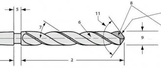
- Working part. Forms a cylindrical hole (or recess). It consists of a cutting part, the length of which for such metal drills is usually half their diameter, and a guide with grooves for removing chips.
- Morse cone. For installation in spindles and tailstocks of machine tools, a tool with a conical shank is used, and for clamping into jaw and collet chucks, a tool with a cylindrical shank is used.
- Paw. These structural elements are present only on tapered shanks and are designed to knock the tool out of the spindle or arbor.
- Neck. Provides convenient approach and retraction of the grinding tool when processing spiral grooves. It does not perform any operational functions, so it is usually marked with a drill bit (embossed directly on the metal).
- Guide part. Also called calibrating. Relying on the walls of a hole drilled in the metal, it directs the tool along its axis. Includes spiral striped surfaces and flutes for chip evacuation.
- The angle of inclination of the spiral surface. For metal processing it is 18÷30°.
- Chip removal groove. The speed of chip removal depends on its width, inclination and surface quality.
- Diameter of the cutting part. Equal to the distance between the outer edges of the cutting edges.
- Cutting edge. This is the sharp edge between the rake face (chip flute) and the back ground surface.
- Main vertex angle. The angle between the cutting edges has a significant impact on the cutting process and the strength of the drilling tool. For metal work, its standard value is 116÷118°.
- Back surface. To reduce friction in the cutting zone, the rear surface is sharpened at an angle to the cutting edge. To drill metal, its value near the ribbon should be 8÷12°.
- Jumper. A structural part common to both rear surfaces.
- Transverse cutting edge. A sharp edge on the bridge separating the rear surfaces. With proper sharpening, in the middle there is the geometric center of the cutting part, which must coincide with the axis of the tool.
- Ribbon. Two strips slightly protruding above the spiral surfaces, which calibrate the hole and reduce friction against its walls.
The general layout of other types of metal drills is similar to this, although depending on their purpose they may differ in the design of the cutting part and chip removal grooves.
I MAKE DRILLS MYSELF
Many fans of amateur technical creativity often have the need to drill a hole of large diameter. Of course, special drills for this are now sold, but sometimes it happens that a suitable factory-made drill is not at hand at the right time. For example, I have been working with metal for several years now, building various homemade products, and when the need arose to drill a hole with a diameter of about 70 mm in channel No. 30 with a wall thickness of 6 mm, there was no equipment for this in my workshop. So I decided to make the tool I needed myself from available materials. I hope my experience will be useful to other DIYers. I offer several options for devices suitable for solving the designated problem.
DRILL FROM… BEARING
I took a used double-row automobile wheel bearing. These cages are made of high-strength steel ШХ15 or ШХ20 with a hardness of 65 HRC units. I reasoned this way: if you make a gear crown from the outer casing, then it should “take” a metal of lower hardness - the same construction channel, for example, made of structural steel. Of course, such a “homemade” won’t last long, you can’t make many holes, but I don’t need many. And wood or drywall can be easily treated with it.
Having shaken out all the contents from the outer race of the bearing, I marked the teeth at one end. To do this, I pasted a template on the clip, which was a strip cut from a school lined notebook. Using a marker, controlling it with a ruler, I marked the teeth evenly around the entire circumference, taking into account the direction of rotation of the future drill.
Sketch of a drill made from a wheel ball bearing with an outer diameter of 72 mm.
The leading edge of the tooth is made perpendicular to the line of the end of the cage or with a slight slope. The inclination depends on the hardness of the material being processed: the softer the material, the sharper the tooth profile should be. The trailing edge is a diagonal line connecting the top of one tooth to the base of the adjacent one. Then, taking a grinder, I cut out the teeth according to the markings. Their height is 10 mm.
Now you need to somehow secure the clip with the cutting edge in the chuck of a drill press or drill (as in my case). To do this, I used the convex cups for fastening the rod of a car shock absorber - they fit inside the homemade “crown” almost without a gap. If they do not fit, then you need to adjust their diameter to the inner diameter of the holder. Using an M12 pin, tighten the cups installed with their convex part to the drill, and clamp the bearing race between them. On the tooth side, the cup is clamped on both sides with nuts. The pin rises 10 - 15 mm above the cutting edge, and at this length it is ground down to a diameter of 10 mm - this is necessary for centering the drill in the workpiece. That is, in the center of the future large-diameter hole, you must first make a “guide” hole with a diameter of 10 mm. In this case, it is important to center the drill relative to the axis of rotation - the M12 pin, if the diameter of the hole in the cup is larger. A 12 mm washer under the nut will help here, selected according to the outer diameter so that its outer edge comes into contact with the concave surface of the cup.
The inclination of the leading edge of the tooth depends on the hardness of the material being processed
The teeth should be cut at even intervals using a paper template.
Car shock absorber rod cups perfectly fix the clip on the axle
The range of wheel bearings allows you to make drills of different diameters.
So, the homemade drill is ready. They should work at low speed, pouring cutting fluid over the cut area, for which I usually use soapy water. The power of the drilling equipment must be sufficient so that the drill does not stop.
The range of wheel bearings of this type is quite large, so you can choose the diameter of the drill in accordance with almost any task. Just go to auto repair shops - old unnecessary bearings and shock absorbers there, as a rule, are simply thrown into scrap metal.
However, I couldn’t “take” high-carbon or stainless steel AiSi304 1.5 mm thick with such a drill... Well, that means we’ll do something else!
THERE WAS A SAW - THERE WAS A DRILL
At the core is the same drill made from a bearing. Moreover, you can even use something that has become completely dull, since now it will only perform auxiliary functions. The cutting part of this tool uses a 30mm wide band saw blade made from high carbon steel.
It is worth noting that there are saw blades made from a variety of steel grades, so before proceeding directly to the manufacture of the device, I recommend conducting a little testing. Press firmly on the blade and try to leave a scratch on the material you plan to drill. If the mark is clear and chips form, then everything is in order - such a saw is suitable. If there is no obvious scuffing or chips, then this blade is not suitable for this task - you need to look for another, harder one.
Fragment of a sketch of a drill with a cutting edge from a band saw.
It is not difficult to estimate the length of the cutting part of the future drill: it is equal to the inner diameter of the bearing race multiplied by the number π. Then we glue a paper template onto the saw on the side opposite the teeth, and using a grinder we make cuts evenly along the entire length to a depth of about 7 mm; they should be perpendicular to the edge.
Next, take a piece of pipe with an outer diameter slightly smaller than the inner diameter of the bearing race and cut it lengthwise on one side. We insert the edge of the saw into the resulting slot and wrap it around the pipe. At this stage, be sure to use safety glasses and gloves, since the elastic, hard saw may burst. By the way, don’t forget about personal protective equipment and when picking up a grinder, remember safety precautions! In the resulting cylindrical segment, slightly bend (without taking off your glasses!) the previously cut comb teeth inward.
A bearing drill bit serves as a tool for securing the saw.
The brand of band saw is selected depending on the hardness of the material being processed
Using personal protective equipment (glasses, gloves), according to a template, we make a notch on the smooth side of the band saw section and bend the teeth of the resulting comb slightly inward.
The cup on the side of the cutting edge of the bearing drill needs to be modified in diameter so that the rolled saw section passes between it and the holder as much as possible tight. We insert the saw into the holder until it stops, so that it protrudes above the holder by 10-15 mm. By tightly tightening the nuts on the central stud, we clamp the saw in the cage. We center the drill similarly to the option described above.
Tested: this drill can (literally) even work with “stainless steel”! But what if you need to make holes of a smaller diameter, but still significantly larger than the diameters of drills usually used in everyday life? Let's say from 20 to 30 mm. I also made equipment for this case.
SECOND LIFE OF THE SQUAD HEAD
The hardness of this tool is about 40 HRC units, which means it is suitable for working with softer materials. A socket tool head is used as a workpiece. If you don’t mind, you can take a normal one, suitable for unscrewing and tightening nuts, but I got my hands on one that was already cracked in several places and practically useless for its intended purpose. Although, I’ll say right away that it’s definitely not worth taking a cheap Chinese head - it’s most likely “plasticine”, and it won’t be able to drill anything. And it is preferable that the head has 12 sides.
Sketch of a drill from a socket tool head
It is better to use a 12-sided tool head as a drill blank
This homemade drill can handle wood, slate, drywall and other less-than-hard materials.
The pitch and size of the teeth can be very different - there is room for experimentation!
A drill from a sister-in-law can be used both as an independent tool and as an accessory for a drill from a bearing.
In my case, the head was very used, but of fairly high quality, impact, with a socket “22”. Its outer diameter is 30 mm. Using the method described above, I marked and cut the teeth - there were only six of them, about 5 mm high. I inserted an M12 pin into the central hole of the head and assembled the drill - I think the reader has already clearly understood the idea. The centering of the stud was carried out by selecting a washer, put on it and in close contact with the inner edges of the head. The shank, which rises 10 - 15 mm above the cutting edge, ensures alignment when drilling.
The wall thickness of this profile is 2 mm, holes with a diameter of 70 mm are made in it with a homemade drill - good job!
Let me summarize. All three drills I made from ferrous metal work. They perfectly drill plastic, drywall, rubber, slate, wood, cellular blocks, aluminum, copper, low-carbon steel (type St.3). Stainless steel can only be drilled using a band saw. It is clear that the resistance and durability of a homemade tool depend both on the hardness of the material being processed and on the quality of the workpieces used for manufacturing. For woodworking, for example, it will last a long time, but when drilling medium-carbon steel, the drill will most likely need to be sharpened frequently. The main advantage of such equipment is its accessibility. To make it, you need worthless waste materials that can be found in the household of any homemade worker, but the result is very useful things.
Rustam SHEIKO, Zaslavl (Belarus)
We recommend reading
- ECONOMICAL WALLS Every individual developer dreams that his house will be not only beautiful and durable, but also inexpensive. Wall structures and materials account for approximately a third of all…
- AVIATION MUSEUM IN MADRID The Madrid Aviation Museum was organized in 1966 (during the life of dictator Franco) and was then located in the building of the Ministry of Aviation (now non-existent in Spain). In 1975...
Types of drills for metal
The main classification of drilling tools is carried out according to their design, since it is directly related to the purpose of a particular type of metal drill. In addition, within the design types, varieties are distinguished according to the type of material for which the given tool is intended for processing (the so-called cutting groups). There is no strict classification for them, but usually the following types are distinguished based on the type of working part:
- spiral;
- feathers;
- centering;
- special.
Among special drills, the largest group is a tool for deep drilling in metal workpieces. Separate subgroups also include products for drilling large diameter holes and stepped cylindrical profiles. It happens that a modern prefabricated tool has such a complex or innovative design that it is classified into several types at once.
Spiral shape
A traditional, widespread type of drilling tool is a twist drill, in which the formation of a cylindrical hole in the metal is carried out by two symmetrical cutting edges. In this case, the removal of the resulting chips passes through spiral grooves, the initial part of which is the front surfaces that form these edges. By design, these products can be monolithic or prefabricated, with a replaceable head or mechanical fastening of cutting inserts. To reduce friction and increase the speed of chip removal, the spiral part is polished and coated with wear-resistant materials.
Step form
Step drills are used to produce shallow-depth holes with fixed step geometry. Such a tool allows you to form two or more cylindrical surfaces in one pass and is most often used in automated processing. By design, modern step drills, as a rule, are a monolithic block that repeats the configuration of the future hole, with rows of cutting plates and straight grooves. The first ones drill an initial hole in the metal of the workpiece, and the ones following them are reaming holes. The biggest problem with this tool is chip removal during machining. Therefore, their use is limited to highly specialized areas.
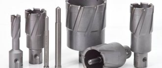
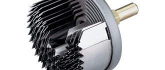
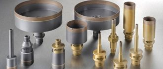
Core drills
A core drill is a hollow tool with a ring arrangement of six or twelve cutting surfaces and a corresponding number of chip removal grooves. It is used for through drilling of large diameter holes in metal. During operation, the cutting edges only cut a ring around the middle of the future hole, and the central part of the metal simply falls out (or is knocked out) after passing through. This tool is classified as a drilling tool, rather, according to an established tradition, since in its operating principle it is much closer to cutters.
Auger drills
When drilling holes in metal to depths that are multiples of 30–40 diameters, elongated drills of a special design with a spiral groove in the form of an auger are used. This solution greatly improves chip removal and allows continuous drilling of metal to the full depth of the hole without periodic withdrawal of the tool. Auger drills differ from conventional spiral drills in the large angles of inclination of the grooves (up to 65°) and their triangular profile. In addition, they have an increased core diameter and a special sharpening of the front surface.
Feather drills
Feather drills are used to make holes in metal covered with casting crust and scale. Structurally, this is the simplest drilling tool, because it has straight grooves and a cutting part in the form of a plate. Its disadvantages are a direct consequence of its simplicity of design and low cost. During the process of drilling metal, feather drills have poor chip removal and tend to move away from the axis of the hole. A plate protruding forward reduces the strength of the entire product, which does not allow working at high feeds, and also requires frequent regrinding. This is a highly specialized tool of increased rigidity, which is used when working with castings and forgings.
Make a hole in the Compass
Making a hole in a compass is easy, today I’ll tell you how. The holes can be blind or through, threaded, conical, countersunk or counterbore, with metric, tapered or pipe threads. You can make a hole in a 3D compass with any necessary parameters in just a few simple steps.
The hole command becomes active when the “Part Editing” panel is activated; the next step is to select the type of hole; to do this, hold down the left mouse button on the icon and move the cursor to the required type.
The hole design can also be selected after pressing the button. In the bottom panel, click the type and select the required one.
Now select the parameters, click on the button to the right. In the window that opens, assign the shape of the end and, if necessary, assign a threaded hole.
I chose a threaded hole with a countersink. The next step is to select the thread type, then the diameter, pitch, thread depth and hole depth, then the countersink diameter and angle.
A counterbore is needed to obtain a chamfer; if you do not know its required diameter, then it is better to simply select a hole, and then make the chamfer using a separate command, or set it not by diameter and angle, as the program suggests, but by depth and angle.
Almost all parameters are set, let's move on to placing the hole on the part. Click on the desired location on the part. The program offers to set offsets from two objects, in cases with a placement surface that has boundaries with straight edges. Reference objects can be changed by selecting distance 1 and distance 2. Icons for changing reference objects in the photo are marked with number 2.
After selecting the reference objects, enter the distance values (number 3 in the photo). Also, distance values are edited using dimensions on the part itself. You can also choose to place the hole by coordinates; this method is selected by selecting the offset (number 4).
For a round part, the hole is placed offset from the center by specifying two sizes.
The compass can make a hole in a round part either from the center and according to coordinates, or with a given angle and diameter at the same time. In order to make a hole in the compass at an angle, you must select a placement according to coordinates on the plane. A polar coordinate system will be required.
We looked at the main ways to get a hole. Another popular method is through-hole cutting, a hand-created chamfer and thread, but this option is not suitable for a sheet body. In cases with a sheet body, the operation of cutting in the sheet body is used. Read about how to carve a compass in the next lesson.
lsapr.ru
Shank types
In accordance with early Soviet GOSTs, which are still in force, two types of shanks were provided for metal drilling tools: cylindrical and conical (Morse). In 1990, GOST 28706-90 was adopted, which duplicated the regulation of ISP 9766-89 for cylindrical shanks with flats. This type of shank is intended for prefabricated metal drills, in which the flat prevents them from turning in the equipment during operation. Now this solution is widely used for modular tools, and where the drill is directly fixed in the spindle, products with a Morse taper are still used.
Countersinking holes
Countersinking is the process of processing holes produced by casting, stamping or machining in order to increase accuracy and reduce roughness.
Countersinking occurs when using a working tool - a countersink.
This tool has three to six blades. Like a drill, the working part of a countersink includes cutting and calibrating parts. The cutting depth is calculated in the same way as when drilling (half the difference in the diameters of the countersink and the hole being machined).
The countersink has the same angles as the drill, with the exception of the angle of inclination of the transverse edge: the countersink does not have it, the angle of inclination of the grooves is ≈10 o -20 o.
A countersink is stronger than a drill. When processing holes of 13-11 quality, countersinking can be the final operation.
Countersinking is used to process cylindrical or conical recesses (for screw heads, sockets, valves, etc.), mating cylindrical and conical, end and other surfaces, through and blind holes.
This method is considered productive - it increases the accuracy of pre-machined holes and partially corrects the curvature of the axis after drilling. To increase the processing accuracy, devices with jig bushings are used.
In practice, in addition to countersinking, counterboring is used. The working tool is a counterbore. Countering is used when it is necessary to obtain grooves, for example for seals, end planes, which are supporting surfaces for bolts, screws or nuts.
Marking of drills according to GOST
The rules for marking drills are regulated by GOST 2034-80. According to this document, markings are not applied to drilling tools with a diameter of less than two millimeters. All information about them must be indicated on the packaging label. For drills with a thickness of over two and up to three millimeters, the marking of a metal drill contains only the diameter value and steel grade (thus they can be distinguished from a tool up to two millimeters). For diameters over three millimeters, the manufacturer must indicate its size, its trademark, metal grade and accuracy class as part of the marking. The grade of the metal from which the tool is made can be indicated both in the form of the GOST designation of steel (for example, R6M7K6), and the international abbreviation generally accepted for high-speed steels (HSS) with the addition of the designation of the main alloying metal (Co, Ni, Ti, etc.) ( see photo below). Foreign manufacturers mark their products in a similar way, so you can distinguish Russian drills from imported ones only by the trademark.
Color designation
In their catalogs, all leading manufacturers of drilling tools use color markings to designate products, provided for by the international standard ISO 513. In accordance with this regulatory document, all tool materials are divided into six groups, each of which is intended for processing certain types of metals, alloys and polymer materials.
| Group | Color | Processed metals and plastics |
| P | Blue | Certain types of carbon, alloy and tool steels. Steels for castings. Some grades of corrosion-resistant steels. |
| M | Yellow | Austenitic corrosion-resistant steels. Certain types of non-magnetic and wear-resistant steels. |
| K | Red | Various brands of cast iron. |
| N | Green | Non-ferrous metals and their alloys. Thermoplastics and duroplasts. |
| S | Golden | Heat-resistant alloys based on nickel, cobalt, titanium and iron. |
| H | Grey | Hardened steels of high hardness. |
In addition, each cutting group is divided into application groups, which are designated by a number in the range from 1 to 40. Groups with a higher index have higher strength, and those with a lower index have greater hardness and wear resistance.
Drill manufacturing technology
Structurally, a twist drill consists of two main components: the working part and the shank. The first is made of high-speed steel or hard alloys, and the second is made of carbon tool steel. The production of twist drills for metal includes the following enlarged stages:
- Preparation of components. Cylindrical blanks for both parts are cut on bar machines and then cleaned of burrs, surface oxides and contaminants.
- Welding. Two parts made of different metals are welded using resistance butt welding. After this, excess metal is removed from the welds, and the workpieces are straightened to give them an accurate cylindrical shape.
- Turning. The workpieces are centered and ground to the exact size. At the same stage, the ends are trimmed, the shank cone is sharpened, and the end of the cone is ground for the foot (for a tool with a cylindrical shank, the last two operations are absent).
- Milling. The foot (for tapered shanks), spiral grooves and flanks are milled. After this, the workpiece is subjected to heat treatment, followed by cleaning in a sandblasting machine.
- Grinding. The grooves of the spirals are ground and polished. After this, the shank and working part are subjected to grinding (with finishing of the reverse cone).
- Drill sharpening.
The housings of prefabricated drilling tools, in which the cutting part is made of carbide plates with brazed or mechanical fastening, are quite complex products, since their manufacture requires complex milling and turning. Therefore, they are usually made on CNC machines or machining centers.
Cutting tools: drawings
| Drawings of cutting tools: cutters, cutters, drills, reamers, taps, broaches, honing heads, cutters, countersinks, countersinks, etc. |
| Drawing of a twist drill... |
| Drill drawing steel 9ХС... |
| Drawing of a straight cutter, with a brazed plate made of VK6 in accordance with GOST 3882-74, rod material steel 45 in accordance with GOST 1050-88, solder L63.. |
| Drawing of a boring cutter, with a brazed plate made of VK8 in accordance with GOST 3882-74, rod material steel 40X in accordance with GOST 4543-88, solder L63 GOST 1.. |
| Drawing of a boring cutter, with a replaceable plate made of T15K6 in accordance with GOST 3882-74, rod material steel 45 in accordance with GOST 1050-88, base plate material VK15... |
| Combined broaching drawing. The material of the working part is high-speed steel R6M5 in accordance with GOST 19265-73, the material of the shank is structural alloyed chromium steel 40X in accordance with GOST 4543-90. Number of teeth - 30... |
| Drawing of a straight cutter, with a brazed plate made of T15K6 in accordance with GOST 3882-74, rod material steel 45 in accordance with GOST 1050-88, solder L.. |
| Drawing of a combined drill-countersink tool... |
| Drawing of a turning cutter with a replaceable insert, the material of the cutting insert is hard alloy VK8 GOST 3882-74, the base plate is hard.. |
| Development drawing... |
| Drawing of a disk modular cutter made of high-speed steel R6M5 GOST 19265-73. Number of teeth z=10, module m=4… |
| Drawing of a chipless tap made of high-speed steel R6M5K5 according to GOST 19265-73... |
| Drawing of a turning cutter with a replaceable insert, the material of the cutting insert is hard alloy T15K6 GOST 3882-74, the support plate is hard.. |
| Drawing of a shaped prismatic cutter, cutting plate material - hard alloy KNT-16 GOST 26530-85, base plate material t.. |
| Drawing of a hob cutter made of high-speed steel R6M5 according to GOST 19265-73. Module m=2, number of entries n=2… |
| Drawing of a three-sided disk cutter with replaceable inserts made of hard alloy VK60M GOST 14959-81, cutter body material - steel 5.. |
| Drawing of a turning cutter with a replaceable insert, the material of the cutting insert is hard alloy KNT-16 GOST 26530-85, the base plate is hard.. |
| Assembly drawing of a honing head ∅65… |
| Drawing of a straight cutter, with a brazed plate made of T5K10 in accordance with GOST 3882-74, rod material steel 45 in accordance with GOST 1050-88, solder L.. |
| Drawing of a boring cutter with a replaceable plate, the material of the cutting plate is hard alloy KTN-16 GOST 26530-85, the base plate is t.. |
| Drawing of a mandrel made of alloyed structural chromium steel 40X according to GOST 4543-88... |
| Drawing of a turning cutter with a replaceable insert, cutting insert material - hard alloy VK60M GOST 3882-74, body material steel 4.. |
| Drawing of a boring cutter with a replaceable plate, the material of the cutting plate is hard alloy KTN-16 GOST 26530-85, the base plate is t.. |
| Drawing of a turning cutter with a replaceable insert, cutting insert material - hard alloy T5K10GOST 3882-74... |
| Drawing of a disk modular cutter made of high-speed steel R6M5 GOST 19265-73. Number of teeth z=10, module m=15... |
| Drawing of a drill with a replaceable insert... |
| Drawing of a prefabricated end mill with replaceable inserts made of VK8 hard alloy, cutter body material - 40X steel... |
| Drawing of a straight cutter, with a brazed plate made of VK6 in accordance with GOST 3882-74, rod material steel 45 in accordance with GOST 1050-88, solder L63.. |
| Drawing of a straight cutter, with a brazed plate made of VK8 in accordance with GOST 3882-74, rod material steel 45 in accordance with GOST 1050-88, solder L63.. |
| Drawing of a prefabricated end mill with replaceable inserts made of hard alloy T15K6 GOST 4872-75, body material - steel 40X GOST 4543-.. |
| Drawing of a mandrel made of alloyed structural chromium steel 20X according to GOST 19281-71... |
| Drawing of a prefabricated end mill with replaceable inserts made of hard alloy T15K6GOST 4872-75, body material - steel 40X GOST 4543-7.. |
| Drawing of a disk cutter made of high-speed steel R6M5 according to GOST 19265-73. Number of teeth z=64… |
| The drawing of the hob cutter was made in the AutoCAD program. The drawing shows methods for attaching a cutter in a quick-change and a conventional cutter.. |
| Drawing of a straight cutter, with a brazed plate made of T15K6 in accordance with GOST 3882-74, rod material steel 45 in accordance with GOST 1050-88, solder L.. |
| Drawing of a disk modular cutter made of high-speed steel R6M5 GOST 19265-73. Number of teeth z=10, module m=2… |
| Assembly drawing of a single-edge drill... |
| Drawing of a prefabricated end mill with replaceable square-shaped inserts made of hard alloy T15K6 in accordance with GOST 4872-75, body material f.. |
| Drawing of a drill with a replaceable insert... |
1-40 41-80 81-120 121-157
techliter.ru
Metal drill size chart
State standards, rules for the manufacture of spiral and centering drills for metal, include tables of size ranges for different designs and directions of rotation of the spiral. Each standard size has a unique digital code designation. For example, if the diameter of a drill with a cylindrical shank is 3.1 mm, it has an N1 design and a right-handed spiral, then its total length should be 65 mm, the length of the working part should be 36 mm, and the code designation of such a product will be 2300-7517. The size tables for metal drills with a tapered shank include a diameter range from 5 to 80 mm, and for tools with a cylindrical shank - from 0.25 to 20 mm. At the same time, for thin drills with a diameter of up to 1 mm, only version N1 with a right-hand spiral is provided.
Drill factories
The production of high-quality metal drills is established at a huge number of factories in Russia and abroad. Products under the following brands are popular.
Ruko. The company specializes in the production of cross-sharpened drills. Types of spraying vary. The products combine high quality and reasonable cost.
Haisser. The carbide drills from this brand are some of the best in the world. The products are expensive.
Bosh. Specializes in the production of drills with SDS shanks.
"Bison". One of the best Russian manufacturers.
SEKIRA. This is our own brand. We produce drills of various types and sizes. The characteristics of all products meet the requirements of GOSTs. You can purchase our products at the lowest price.
Study the catalog, select the drills you need and place your order. We will deliver metal-cutting tools on time.
Manufacturing materials and coatings
The main materials for the manufacture of working parts of monolithic drilling tools are high-speed steels and hard alloys.
Steels with tungsten or tungsten-molybdenum alloys are most often used as high-speed cutters. The latter are also used in a version with the addition of cobalt. Hard alloys, which are produced by powder metallurgy methods, are more durable, stronger and heat-resistant than high-speed steels. They usually contain several refractory metals such as tungsten, titanium, cobalt and tantalum. Some products designed to perform several technological operations in one tool installation (for example, a combination drill) may include components made from different tool materials. To improve the performance of metal drills, their surfaces are subjected to additional processing or coated with hard metal compounds. The most common processing methods that increase the strength and wear resistance of tools are cyanidation and sulfidation. And for protective coatings, titanium carbonitride (TiCN), including alloyed aluminum (TiAlN), is usually used.
Features of drill manufacturing, additional methods for improving tool performance
We will talk about the features of performing the most important operations included in drill manufacturing technology, and describe the methods that are used to improve the basic characteristics of tools.
Heat treatment
It is very important. The wear resistance of the tool and the quality of the steel directly depend on the correctness of the heat treatment.
Hardening is carried out in baths with molten salts or in furnaces (electric and gas). In some cases, equipment with a vacuum or a reducing atmosphere is used to make drills.
For tempering, oils, alkalis, salts and water are used. Often the workpieces are cooled in air.
Note! Heat treatment modes are of particular importance. Therefore, all processes are controlled automatically.
Resistance butt welding
Performed on special electric welding machines. There are three technologies.
Continuous flash welding without heating. The technology is highly productive. The disadvantage is the high consumption of metal for melting and upsetting.
Heated intermittent flash welding. Takes a little longer. Metal consumption is significantly reduced.
Heated resistance welding. Almost no metal is consumed, but the operation requires highly qualified workers.
The second method is most often used.
Photo No. 3: contact butt welding
Additional methods for improving the basic characteristics of drills
Let us list the technologies that are used in the manufacture of drills to further improve their properties.
Cyanidation. The surfaces of the working parts are saturated with nitrogen and carbon. Cyanidation increases the strength of tools by 2–3 times.
Sulfidation. The surface layers of drills are saturated with sulfur. Sulfur compounds reduce friction and increase the wear resistance of tools by 1.5–2 times.
Steam treatment. After this, the instruments are placed in oil. Black oxide films form on surfaces. The strength of drills that have undergone this treatment is doubled.
How to choose a drill for the metal being processed
When choosing a drill for metal work, first of all you need to familiarize yourself with the color markings of the ISO 513 standard, which all manufacturers of drilling tools adhere to. It should be understood that such markings are not applied to the product itself, but are present only in its catalog description. You can, of course, rely on the advice of a consultant in a tool store, but this method is only suitable if you need to select a drill bit for a drill designed to work with ordinary structural steel. If you have to drill hard or tough metals or require high-quality custom work, then it is better to follow the recommendations of professionals. The figure below shows an example of the use of color coding from the Mitsubishi catalog.
It must also be remembered that the parameters of the drilling process depend both on the characteristics of the drill and on the power and rotation speed of the drive. Therefore, it is better not to use drill bits for a screwdriver with a drill, as this will most likely lead to their damage. And the rotation speed of the screwdriver is clearly not enough for drilling metal with conventional drill bits.
Drills used in machine tools
On drilling machines in which the spindle mounting hole is made under a Morse taper, drills for metal processing are installed directly into the spindle. And to fix them, it has a special through groove for wedging the foot. The same drills are also used in universal machines (drilling and milling, etc.), in which the spindle mounting hole is made for a metric cone or one of its modern varieties. Only in this case are they inserted into transition mandrels with the appropriate cone. In general, metal drills used on machine tools do not differ from those used when drilling with hand tools. The only type of drilling tool intended only for machine tool use is a drill with a through channel designed to supply coolant to the processing zone (see figure below).
The best manufacturers
Among Russian manufacturers of drilling tools for metal work, the products of the Volzhsky Tool Plant (VIZ) and Tomsk Tool Plant have a good price-quality ratio. The tools of the Ukrainian Zaporozhye Tool Plant (ZIZ) belong to this category. The best quality drills are from world-famous manufacturers of cutting tools, such as German Bosch, Hasser and Ruko, Swedish Sandvik, Japanese Mitsubishi, Taiwanese Winstar, etc. But their products have a fairly high price and are intended mainly for professional use. In addition, metal drills are widely available on the market under the trademarks of well-known sellers and manufacturers of power tools. Basically, this is an inexpensive tool, but many products are of very high quality. In this category, users most often refer to Interskol, DeWalt, Hilti, Makita and Metabo.
Blueprints
| (drawings saved in Compass-3D v.13) |
| Cutting tools |
| 7 |
| 31 |
| 32 |
| 33 |
| 34 |
| 35 |
| 36 |
| 37 |
| 38 |
| 39 |
| 40 |
| 41 |
| 42 |
| 43 |
| 44 |
| 45 |
| 46 |
| 47 |
| 48 |
| 49 |
cadregion.ru
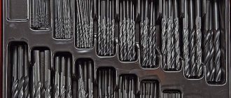
Rules for storing drills
At workplaces of industrial enterprises, drills are stored in tool cabinets and bedside tables made of sheet metal, installed in the immediate vicinity of the machine, as well as on racks in special tool storage rooms. Drilling tools must be placed in a certain order (by type and diameter) in the appropriate compartments, cases or cases. Laying should ensure the safety of cutting edges, as well as working and seating surfaces. Before storing the drilling tool, clean it of metal dust and contaminants, and if not used for a long time, lubricate it with lithol or technical petroleum jelly. In order to prevent corrosion, it is prohibited to place acid-containing or other aggressive liquids near the tool storage areas. In home workshops, tools should be stored in compliance with the same rules. Only instead of bedside tables and cabinets, it is much more convenient to use plastic pencil cases and special stands (see video below).
When drilling deep holes in metal, it is recommended to pour a small amount of oil on the surface of the tool. I-20 is usually used in production, but not everyone has the opportunity to purchase this particular brand. What kind of oil can be used at home instead of industrial oil? Please share your thoughts and recommendations on this issue in the comments.