Minimum thickness of measurement objects depending on their hardness and load magnitude
X axis
— thickness of the test sample, mm;
Y
axis - hardness HV
Figure A.1 - Minimum thickness of test specimens depending on test load and hardness (for scales from HV 0.2 to HV 100)
1
— hardness number HV;
2
—minimum sample thickness
t
, mm;
3
— imprint diagonal length
d
, mm;
4
- designation of the hardness scale HV;
5
- test load
F
, N
Figure A.2 - Nomogram for determining the characteristics of Vickers hardness measurement based on the minimum thickness of samples (for scales from HV 0.01 to HV 100)
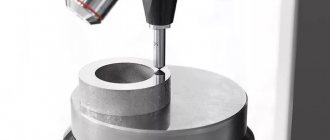
Hardness measurements
Measurement of the hardness of pipeline metal and welded joints should be carried out in accessible places for pipeline elements (pipe, bend (elbow, bend), transition, forged (cast) tee, etc.), as a rule, in places where thickness gauging is performed. It is allowed to measure the hardness of pipeline elements and welded joints selectively by one representative of each, and the selection of representatives should be carried out for a group of similar elements with the same material design, which are located in the zone of maximum power and thermal loads. At each location identified by the surveyors, at least three measurements must be taken. In the area of welds, hardness is determined on both sides of the weld line in each of three zones: base metal, heat-affected zone (HAZ), weld. At least 3 measurements are taken in each zone, and their arithmetic mean value or range of values is taken as the result.
Hardness testing is performed in all cases where there is doubt about the quality of the metal or weld.
The hardness of studs and nuts is measured selectively (one to three products) on at least two or three pipelines of a process plant operating at temperatures above 450 0 C for carbon steels and above 500 0 C for alloy steels.
If the result obtained shows that the hardness of the metal in a section of the pipeline (or a welded joint, deposited metal) does not comply with the regulatory and technical documentation, then the metal of such a section of the pipeline is subject to examination with cutting out a sample or is rejected.
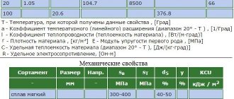
If the hardness of fasteners (studs, bolts, nuts) deviates from the standard values indicated in Table 18, then they are rejected.
Table 18 - Mechanical properties of steels for fasteners
Table of correction factors for measurements on curved surfaces
B.1 Spherical surfaces
Tables B.1 and B.2 give correction factors when hardness measurements are performed on spherical surfaces.
Correction factors are given for the ratio of the average length of the print diagonals to the diameter D
spherical sample on which measurements are performed.
Example
:
The diameter
of the spherical sample is D
=
10 mm
.
Load
F
=
98.07
N.
_
_ _
The
average
length print diagonals
is d
=
0.150
mm .
Vickers hardness
= _
The
correction
factor is
obtained from Table B.1 by interpolation
=
0.983 .
The hardness
of
the spherical sample
is
824 ×
0.983 =
810 H V 10
.
Table B.1 - Convex spherical surfaces
| d / d | Correction factor | d / | Correction factor |
| 0,004 | 0,995 | 0,086 | 0,920 |
| 0,009 | 0,990 | 0,093 | 0,915 |
| 0,013 | 0,985 | 0,100 | 0,910 |
| 0,018 | 0,980 | 0,107 | 0,905 |
| 0,023 | 0,975 | 0,114 | 0,900 |
| 0,028 | 0,970 | 0,122 | 0,895 |
| 0,033 | 0,965 | 0,130 | 0,890 |
| 0,038 | 0,960 | 0,139 | 0,885 |
| 0,043 | 0,955 | 0,147 | 0,880 |
| 0,049 | 0,950 | 0,156 | 0,875 |
| 0,055 | 0,945 | 0,165 | 0,870 |
| 0,061 | 0,940 | 0,175 | 0,865 |
| 0,067 | 0,935 | 0,185 | 0,860 |
| 0,073 | 0,930 | 0,195 | 0,855 |
| 0,079 | 0,925 | 0,206 | 0,850 |
Table B.2 - Concave spherical surfaces
| d / d | Correction factor | d / | Correction factor |
| 0,004 | 1,005 | 0,038 | 1,050 |
| 0,008 | 1,010 | 0,041 | 1,055 |
| 0,012 | 1,015 | 0,045 | 1,060 |
| 0,016 | 1,020 | 0,048 | 1,065 |
| 0,020 | 1,025 | 0,051 | 1,070 |
| 0,024 | 1,030 | 0,054 | 1,075 |
| 0,028 | 1,035 | 0,057 | 1,080 |
| 0,031 | 1,040 | 0,060 | 1,085 |
| 0,035 | 1,045 | 0,063 | 1,090 |
| 0,066 | 1,095 | 0,082 | 1,125 |
| 0,069 | 1,100 | 0,084 | 1,130 |
| 0,071 | 1,105 | 0,087 | 1,135 |
| 0,074 | 1,110 | 0,089 | 1,140 |
| 0,077 | 1,115 | 0,091 | 1,145 |
| 0,079 | 1,120 | 0,094 | 1,150 |
B.2 Cylindrical surfaces
Tables B.3 - B.6 give correction factors when hardness measurements are performed on cylindrical surfaces.
Correction factors are given for the ratio of the average length of the print diagonals to the diameter D
cylindrical sample on which measurements are performed.
Example
:
Cylindrical
sample
,
one of imprint diagonals is parallel to cylinder axis D
=
5 mm
.
The average
length
of print diagonals
is d
=
0.415 mm
.
Load
F
=
294.2
N.
_
_ _
Vickers hardness
= _
The
correction
factor is
obtained from table B.6
=
1.075 .
Hardness of
a
cylindrical sample
=
323 ×
1.075 =
347 H V 30
.
Table B.3 - Convex cylindrical surfaces. Diagonals are rotated 45° relative to the cylinder axis
| d / d | Correction factor | d / | Correction factor |
| 0,009 | 0,995 | 0,119 | 0,935 |
| 0,017 | 0,990 | 0,129 | 0,930 |
| 0,026 | 0,985 | 0,139 | 0,925 |
| 0,035 | 0,980 | 0,149 | 0,920 |
| 0,044 | 0,975 | 0,159 | 0,915 |
| 0,053 | 0,970 | 0,169 | 0,910 |
| 0,062 | 0,965 | 0,179 | 0,905 |
| 0,071 | 0,960 | 0,189 | 0,900 |
| 0,081 | 0,955 | 0,200 | 0,895 |
| 0,090 | 0,950 | ||
| 0,100 | 0,945 | ||
| 0,109 | 0,940 |
Table B.4 - Concave cylindrical surfaces. Diagonals are rotated 45° relative to the cylinder axis
| d / d | Correction factor | d / | Correction factor |
| 0,009 | 1,005 | 0,082 | 1,050 |
| 0,017 | 1,010 | 0,089 | 1,055 |
| 0,025 | 1,015 | 0,097 | 1,060 |
| 0,034 | 1,020 | 0,104 | 1,065 |
| 0,042 | 1,025 | 0,112 | 1,070 |
| 0,050 | 1,030 | 0,119 | 1,075 |
| 0,058 | 1,035 | 0,127 | 1,080 |
| 0,066 | 1,040 | 0,134 | 1,085 |
| 0,074 | 1,045 | 0,141 | 1,090 |
| 0,148 | 1,095 | 0,189 | 1,125 |
| 0,155 | 1,100 | 0,196 | 1,130 |
| 0,162 | 1,105 | 0,203 | 1,135 |
| 0,169 | 1,110 | 0,209 | 1,140 |
| 0,176 | 1,115 | 0,216 | 1,145 |
| 0,183 | 1,120 | 0,222 | 1,150 |
Table B.5 - Convex cylindrical surfaces. One of the diagonals is parallel to the cylinder axis
| d / d | Correction factor | d / | Correction factor |
| 0,009 | 0,995 | 0,085 | 0,965 |
| 0,019 | 0,990 | 0,104 | 0,960 |
| 0,029 | 0,985 | 0,126 | 0,955 |
| 0,041 | 0,980 | 0,153 | 0,950 |
| 0,054 | 0,975 | 0,189 | 0,945 |
| 0,068 | 0,970 | 0,243 | 0,940 |
Table B.6 - Concave cylindrical surfaces. One of the diagonals is parallel to the cylinder axis
| d / d | Correction factor | d / | Correction factor |
| 0,008 | 1,005 | 0,087 | 1,080 |
| 0,016 | 1,010 | 0,090 | 1,085 |
| 0,023 | 1,015 | 0,093 | 1,090 |
| 0,030 | 1,020 | 0,097 | 1,095 |
| 0,036 | 1,025 | 0,100 | 1,100 |
| 0,042 | 1,030 | 0,103 | 1,105 |
| 0,048 | 1,035 | 0,105 | 1,110 |
| 0,053 | 1,040 | 0,108 | 1,115 |
| 0,058 | 1,045 | 0,111 | 1,120 |
| 0,063 | 1,050 | 0,113 | 1,125 |
| 0,067 | 1,055 | 0,116 | 1,130 |
| 0,071 | 1,060 | 0,118 | 1,135 |
| 0,076 | 1,065 | 0,120 | 1,140 |
| 0,079 | 1,070 | 0,123 | 1,145 |
| 0,083 | 1,075 | 0,125 | 1,150 |
GOST 2999-75 (ST SEV 470-77) Vickers hardness measurement method
GOST 2999-75 (ST SEV 470-77)
METALS AND ALLOYS. Vickers hardness measurement method
Metals and alloys. Vickers hardness test by diamond pyramid
OKSTU 1909 Date of introduction 1976-07-01* ______________________________ * The validity period was lifted according to Protocol N 5-94 of the Interstate Council for Standardization, Metrology and Certification (IUS N 2, 1993).
APPROVED AND ENTERED INTO EFFECT by Resolution of the State Committee of Standards of the Council of Ministers of the USSR dated July 28, 1975 No. 1956
Verified in 1985 by Decree of the State Standard of September 27, 1985 N 3118, the validity period was extended until July 1, 1993
INSTEAD OF GOST 2999-59 RE-ISSUE (December 1986) with Amendments No. 1, 2, approved in May 1979, September 1985 (IUS 7-79, 12-85).
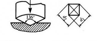
This standard establishes a method for measuring the Vickers hardness of ferrous and non-ferrous metals and alloys under loads from 9.807 N (1 kgf) to 980.7 N (100 kgf). Hardness measurement is based on pressing a diamond tip in the shape of a regular tetrahedral pyramid into a sample (product) under the influence of a load F applied for a certain time, and measuring the indentation diagonals d1, d2 remaining on the surface of the sample after the load is removed. The standard fully complies with ST SEV 470-77 (reference appendix 2). (Changed edition, Amendment No. 1, 2).
1. SAMPLING METHODS
1.1. When making a sample and preparing its surface, it is necessary to take measures to prevent the possibility of changes in the properties of the metal due to heating or hardening. 1.2. The minimum sample thickness for steel products should be 1.2 times greater than the indentation diagonal; for products made of non-ferrous metals - 1.5 times. Note. The minimum thickness of a sample (product) for non-ferrous metals is determined according to the nomogram given in the recommended Appendix 3. (Changed edition, Amendment No. 1). 1.3. When measuring hardness on curved surfaces, the radius of curvature must be at least 5 mm. Note. To determine hardness on samples with a radius of curvature of less than 5 mm, correction factors are used that are used for cylindrical and spherical surfaces, depending on the value of the d/D ratio given in recommended Appendix 4. (Modified edition, Amendment No. 1).
2. EQUIPMENT
2.1. The device for measuring hardness must comply with the requirements of GOST 23677-79 and this standard. The diamond tip must comply with the requirements of GOST 9377-81. 2.3. Exemplary hardness measures must comply with the requirements of GOST 9031-75.
3. PREPARATION FOR THE TEST
3.1. Before measuring hardness, samples (products) are inspected. 3.2. The surface of the test sample must have a roughness of no more than 0.16 microns according to GOST 2789-73 and be free from oxide film and foreign substances. 3.3. When measuring hardness, it must be ensured that the applied force is perpendicular to the surface being tested. 3.4. The supporting surface of the table must be clean. The sample must lie rigidly and stable on the stand. 3.5. When measuring hardness with a diamond pyramid, the following loads are used: 9.807 (1); 19.61 (2); 24.52 (2.5); 29.42 (3); 49.03 (5); 98.07 (10); 196.1 (20); 294.2 (30); 490.3 (50); 980.7 (100) N (kgf). To obtain a more accurate hardness measurement result, the load should be as large as possible, and there should be no noticeable signs of deformation on the back side of the sample. Note. To determine the hardness of ferrous metals and alloys, loads from 49.03 N (5 kgf) to 980.7 N (100 kgf) are used; for copper and its alloys - from 24.52 N (2.5 kgf) to 490.3 N (50 kgf); for aluminum alloys - from 9.807 N (1 kgf) to 980.7 N (100 kgf). (Changed edition, Amendment No. 1, 2).
4. CONDUCT OF THE TEST
4.1. When measuring hardness, the following conditions must be met: a) a smooth increase in load to the required value; b) maintaining a constant applied load for a specified time. 4.2. The duration of exposure under load should be 10-15 s. 4.3. If there are special instructions in the standards or technical conditions for metal products, it is allowed to conduct tests with a longer holding time under load. In this case, the shutter speed tolerance should be ±2 s. 4.4. The distance between the center of the print and the edge of the sample or the edge of an adjacent print must be at least 2.5 times the length of the diagonal of the print. 4.5. If the thickness of the test layer is unknown, several measurements should be made under different loads. If at the same time the hardness changes, then the loads should be reduced until, under two adjacent loads, the hardness is close in value or coincides. 4.6. The test is carried out at a temperature of +20°C. In case of disagreement in hardness measurements, tests should be carried out at temperatures of (20 ± 2) °C in temperate climates and at (27 ± 2) °C in tropical climates. (Introduced additionally, Amendment No. 1). 4.7. The number of prints when determining hardness is indicated in the regulatory and technical documentation for metal products. (Introduced additionally, Amendment No. 1).
5. PROCESSING RESULTS
5.1. Vickers hardness (HV) is calculated using the formula
where F is the load, N.
where P is load, kgf;
— the angle between the opposite faces of the pyramid at the apex, equal to 136°;
— arithmetic mean value of the lengths of both diagonals of the print after removing the load, mm.
(Changed edition, Amendment No. 2).
5.2. To determine Vickers hardness, take the arithmetic average of the lengths of both diagonals (see drawing). The difference between the diagonals of one print should not exceed 2% of the smaller one.
For anisotropic materials, the resulting difference in the lengths of two diagonals of one print may not fit within the specified tolerance. The tolerance for this difference must be specified in the standards or technical specifications for metal products.
(Changed edition, Amendment No. 2).
5.3. Measurement of diagonals up to 0.2 mm in length inclusive should be carried out with an error of no more than ±0.001 mm, and for diagonals with a length of more than 0.2 mm - with an error of no more than ±0.5%. 5.4. Vickers hardness under test conditions F = "294.2" N (30 kgf) and a holding time under load of 10-15 s - is indicated by numbers characterizing the hardness value and the letters HV. Under other test conditions, the load and holding time are indicated after the letters HV. Examples of designation: 500 HV - Vickers hardness, obtained at a load F = "30 kgf and a holding time of 10-15 s; 220 HV10/40 - Vickers hardness obtained at a load of 98.07 (10 kgf) and a holding time of 40 s. (Changed edition, Amendment No. 1, 2).
5.5. The Vickers hardness, calculated using the specified formula, depending on the length of the diagonal of the indentation at standard values of their load F, is given in the appendix.
6. TEST PROTOCOL
The test report should indicate: the magnitude of the load; hardness values; duration of exposure under load; imprint diagonals (in the case of testing according to clause 5.2); sample designation. (Introduced additionally, Amendment No. 1).
APPENDIX 1. HARDNESS WHEN TESTING WITH A DIAMOND PYRAMID ACCORDING TO VICKERS
ANNEX 1
Load 9.807 (1 kgf)
Table 1
| Print diagonal, mm | Hardness values | |||||||||
| 0,000 | 0,001 | 0,002 | 0,003″ | 0,004 | 0,005 | 0,006 | 0,007 | 0,008 | 0,009 | |
| 0,03 | 2060 | 1930 | 1811 | 1703 | 1604 | 1514 | 1431 | 1355 | 1284 | 1219 |
| 0,04 | 1159 | 1103 | 1051 | 1003 | 958 | 916 | 876 | 839 | 805 | 772 |
| 0,05 | 742 | 713 | 686 | 660 | 636 | 613 | 591 | 571 | 551 | 533 |
| 0,06 | 515 | 498 | 482 | 467 | 453 | 439 | 426 | 413 | 401 | 389 |
| 0,07 | 378 | 368 | 358 | 348 | 339 | 330 | 321 | 313 | 305 | 297 |
| 0,08 | 290 | 283 | 276 | 269 | 263 | 257 | 251 | 245 | 239 | 234 |
| 0,09 | 229 | 224 | 219 | 214 | 210 | 205 | 201 | 197 | 193 | 189 |
| 0,10 | 185 | 182 | 178 | 175 | 171 | 168 | 165 | 162 | 159 | 156 |
| 0,11 | 153 | 151 | 148 | 145 | 143 | 140 | 138 | 135 | 133 | 131 |
| 0,12 | 129 | 127 | 125 | 123 | 121 | 119 | 117 | 115 | 113 | 111 |
| 0,13 | 110 | 108 | 106 | 105 | 103 | 102 | 100 | 98,8 | 97,4 | 96,0 |
| 0,14 | 94,6 | 93,3 | 92,0 | 90,7 | 89,4 | 88,2 | 87,0 | 85,8 | 84,7 | 83,5 |
| 0,15 | 82,4 | 81,3 | 80,3 | 79,2 | 78,2 | 77,2 | 76,2 | 75,2 | 74,3 | 73,4 |
| 0,16 | 72,4 | 71,5 | 70,7 | 69,8 | 68,9 | 68,1 | 67,3 | 66,5 | 65,7 | 64,9 |
| 0,17 | 64,2 | 63,4 | 62,7 | 62,0 | 61,2 | 60,6 | 59,9 | 59,2 | 58,5 | 57,9 |
| 0,18 | 57,2 | 56,6 | 56,0 | 55,4 | 54,8 | 54,2 | 53,6 | 53,0 | 52,5 | 51,9 |
| 0,19 | 51,4 | 50,8 | 50,3 | 49,8 | 49,3 | 48,8 | 48,3 | 47,8 | 47,3 | 46,8 |
| 0,20 | 46,4 | 45,9 | 45,4 | 45,0 | 44,6 | 44,1 | 43,7 | 43,3 | 42,9 | 42,5 |
| 0,21 | 42,0 | 41,7 | 41,3 | 40,9 | 40,5 | 40,1 | 39,7 | 39,4 | 39,0 | 38,7 |
| 0,22 | 38,3 | 38,0 | 37,6 | 37,3 | 37,0 | 36,6 | 36,3 | 36,0 | 35,7 | 35,4 |
| 0,23 | 35,1 | 34,8 | 34,5 | 34,2 | 33,9 | 33,6 | 33,3 | 33,0 | 32,7 | 32,5 |
| 0,24 | 32,2 | 31,9 | 31,7 | 31,4 | 31,1 | 30,9 | 30,6 | 30,4 | 30,2 | 29,9 |
| 0,25 | 29,7 | 29,4 | 29,2 | 29,0 | 28,7 | 28,5 | 28,3 | 28,1 | 27,9 | 27,6 |
| 0,26 | 27,4 | 27,2 | 27,0 | 26,8 | 26,6 | 26,4 | 26,2 | 26,0 | 25,8 | 25,6 |
| 0,27 | 25,4 | 25,2 | 25,1 | 24,9 | 24,7 | 24,5 | 24,3 | 24,2 | 24,0 | 23,8 |
| 0,28 | 23,7 | 23,5 | 23,3 | 23,2 | 23,0 | 22,8 | 22,7 | 22,5 | 22,4 | 22,2 |
| 0,29 | 22,0 | 21,9 | 21,7 | 21,6 | 21,5 | 21,3 | 21,2 | 21,0 | 20,9 | 20,7 |
| 0,30 | 20,6 | 20,5 | 20,3 | 20,2 | 20,1 | 19,9 | 19,8 | 19,7 | 19,5 | 19,4 |
| 0,31 | 19,3 | 19,2 | 19,0 | 18,9 | 18,8 | 18,7 | 18,6 | 18,5 | 18,3 | 18,2 |
| 0,32 | 18,1 | 18,0 | 17,9 | 17,8 | 17,7 | 17,6 | 17,4 | 17,3 | 17,2 | 17,1 |
| 0,33 | 17,0 | 16,9 | 16,8 | 16,7 | 16,6 | 16,5 | 16,4 | 16,3 | 16,2 | 16,1 |
| 0,34 | 16,04 | 15,95 | 15,85 | 15,76 | 15,67 | 15,58 | 15,49 | 15,40 | 15,31 | 15,22 |
| 0,35 | 15,14 | 15,05 | 14,98 | 14,88 | 14,80 | 14,71 | 14,63 | 14,55 | 14,47 | 14,39 |
| 0,36 | 14,31 | 14,23 | 14,15 | 14,07 | 14,00 | 13,92 | 13,84 | 13,77 | 13,69 | 13,62 |
| 0,37 | 13,55 | 13,47 | 13,40 | 13,33 | 13,26 | 13,19 | 13,12 | 13,05 | 12,98 | 12,91 |
| 0,38 | 12,84 | 12,77 | 12,71 | 12,64 | 12,58 | 12,51 | 12,45 | 12,38 | 12,32 | 12,25 |
| 0,39 | 12,19 | 12,13 | 12,07 | 12,01 | 11,95 | 11,89 | 11,83 | 11,77 | 11,71 | 11,65 |
| 0,40 | 11,59 | 11,53 | 11,47 | 11,42 | 11,36 | 11,31 | 11,25 | 11,19 | 11,14 | 11,09 |
| 0,41 | 11,03 | 10,98 | 10,92 | 10,87 | 10,82 | 10,77 | 10,72 | 10,66 | 10,61 | 10,56 |
| 0,42 | 10,51 | 10,46 | 10,41 | 10,36 | 10,31 | 10,27 | 10,22 | 10,17 | 10,12 | 10,08 |
| 0,43 | 10,03 | 9,08 | 9,94 | 9,89 | 9,85 | 9,80 | 9,75 | 9,71 | 9,67 | 9,62 |
| 0,44 | 9,58 | 9,53 | 9,49 | 9,45 | 9,41 | 9,36 | 9,32 | 9,28 | 9,24 | 9,20 |
| 0,45 | 9,16 | 9,12 | 9,08 | 9,04 | 9,00 | 8,96 | 8,92 | 8,88 | 8,84 | 8,80 |
| 0,46 | 8,76 | 8,73 | 8,69 | 8,65 | 8,61 | 8,58 | 8,54 | 8,50 | 8,47 | 8,43 |
| 0,47 | 8,39 | 8,36 | 8,32 | 8,29 | 8,25 | 8,22 | 8,18 | 8,15 | 8,12 | 8,08 |
| 0,48 | 8,05 | 8,02 | 7,98 | 7,95 | 7,92 | 7,88 | 7,85 | 7,82 | 7,79 | 7,75 |
| 0,49 | 7,72 | 7,69 | 7,66 | 7,63 | 7,60 | 7,57 | 7,54 | 7,51 | 7,48 | 7,45 |
| 0,50 | 7,42 | 7,39 | 7,36 | 7,33 | 7,30 | 7,27 | 7,24 | 7,21 | 7,19 | 7,16 |
| 0,51 | 7,13 | 7,10 | 7,07 | 7,05 | 7,02 | 6,99 | 6,96 | 6,94 | 6,91 | 6,88 |
| 0,52 | 6,86 | 6,83 | 6,81 | 6,78 | 6,75 | 6,73 | 6,70 | 6,68 | 6,65 | 6,63 |
| 0,53 | 6,60 | 6,58 | 6,55 | 6,53 | 6,50 | 6,48 | 6,45 | 6,43 | 6,41 | 6,38 |
| 0,54 | 6,36 | 6,34 | 6,31 | 6,29 | 6,27 | 6,24 | 6,22 | 6,20 | 6,17 | 6,15 |
| 0,55 | 6,13 | 6,11 | 6,09 | 6,06 | 6,04 | 6,02 | 6,00 | 5,98 | 5,96 | 5,93 |
| 0,56 | 5,91 | 5,89 | 5,87 | 5,85 | 5,83 | 5,81 | 5,79 | 5,77 | 5,75 | 5,73 |
| 0,57 | 5,71 | 5,69 | 5,67 | 5,65 | 5,63 | 5,61 | 5,59 | 5,57 | 5,55 | 5,53 |
| 0,58 | 5,51 | 5,49 | 5,47 | 5,46 | 5,44 | 5,42 | 5,40 | 5,38 | 5,36 | 5,35 |
| 0,59 | 5,33 | 5,31 | 5,29 | 5,27 | 5,26 | 5,24 | 5,22 | 5,20 | 5,19 | 5,17 |
| 0,60 | 5,15 | 5,13 | 5,12 | 5,10 | 5,08 | 5,07 | 5,05 | 5,03 | 5,02 | 5,00 |
Note. To calculate the hardness numbers at loads of 19.61 (2), 24.52 (2.5), 29.42 (3) N (kgf), the hardness value must be multiplied by 2.0; 2.5; 3.0.
table 2
Load 49.03 N (5 kgf)
| Print diagonal, mm | Hardness values | |||||||||
| 0,000> | 0,001 | 0,002 | 0,003 | 0,004 | 0,005 | 0,006 | 0,007 | 0,008 | 0,009 | |
| 0,06 | 2576 | 2492 | 2412 | 2336 | 2264 | 2195 | 2129 | 2065 | 2005 | 1947 |
| 0,07 | 1892 | 1839 | 1789 | 1740 | 1693 | 1648 | 1605 | 1564 | 1524 | 1486 |
| 0,08 | 1449 | 1413 | 1379 | 1346 | 1314 | 1283 | 1254 | 1225 | 1197 | 1171 |
| 0,09 | 1145 | 1120 | 1095 | 1072 | 1049 | 1027 | 1006 | 985 | 965 | 946 |
| 0,10 | 927 | 909 | 891 | 874 | 857 | 841 | 825 | 810 | 795 | 780 |
| 0,11 | 766 | 753 | 739 | 726 | 713 | 701 | 689 | 677 | 666 | 655 |
| 0,12 | 644 | 633 | 623 | 613 | 603 | 593 | 584 | 575 | 566 | 557 |
| 0,13 | 545 | 540 | 532 | 524 | 516 | 509 | 501 | 494 | 487 | 480 |
| 0,14 | 473 | 466 | 460 | 453 | 447 | 441 | 435 | 429 | 423 | 418 |
| 0,15 | 412 | 407 | 401 | 396 | 391 | 386 | 381 | 376 | 371 | 367 |
| 0,16 | 362 | 358 | 353 | 349 | 345 | 341 | 336 | 332 | 329 | 325 |
| 0,17 | 321 | 317 | 313 | 310 | 306 | 303 | 299 | 296 | 293 | 289 |
| 0,18 | 286 | 283 | 280 | 277 | 274 | 271 | 268 | 265 | 262 | 260 |
| 0,19 | 257 | 254 | 252 | 249 | 246 | 244 | 241 | 239 | 237 | 234 |
| 0,20 | 232 | 229 | 227 | 225 | 223 | 221 | 218 | 216 | 214 | 212 |
| 0,21 | 210 | 208 | 206 | 204 | 202 | 201 | 199 | 197 | 195 | 193 |
| 0,22 | 192 | 190 | 188 | 186 | 185 | 183 | 182 | 180 | 178 | 177 |
| 0,23 | 175 | 174 | 172 | 171 | 169 | 168 | 166 | 165 | 164 | 162 |
| 0,24 | 161 | 160 | 158 | 157 | 156 | 154 | 153 | 152 | 151 | 150 |
| 0,25 | 148 | 147 | 146 | 145 | 144 | 143 | 141 | 140 | 139 | 138 |
| 0,26 | 137 | 136 | 135 | 134 | 133 | 132 | 131 | 130 | 129 | 128 |
| 0,27 | 127 | 126 | 125 | 124 | 123,5 | 122,6 | 121,7 | 120,8 | 120,0 | 119,1 |
| 0,28 | 118,3 | 117,4 | 116,6 | 115,8 | 115,0 | 114,2 | 113,4 | 112,6 | 111,8 | 111,0 |
| 0,29 | 110,2 | 109,5 | 108,7 | 108,0 | 107,3 | 106,5 | 105,8 | 105,1 | 104,4 | 103,7 |
| 0,30 | 103,0 | 102,3 | 101,7 | 101,0 | 100,3 | 99,7 | 99,0 | 98,4 | 97,7 | 97,1 |
| 0,31 | 96,5 | 95,9 | 95,2 | 94,6 | 94,0 | 93,4 | 92,9 | 92,3 | 91,7 | 91,1 |
| 0,32 | 90,5 | 90,0 | 89,4 | 88,9 | 88,3 | 87,8 | 87,2 | 86,7 | 86,2 | 85,7 |
| 0,33 | 85,1 | 84,6 | 84,1 | 83,6 | 83,1 | 82,6 | 82,1 | 81,6 | 81,2 | 80,7 |
| 0,34 | 80,2 | 79,7 | 79,3 | 78,8 | 78,4 | 77,9 | 77,4 | 77,0 | 76,6 | 76,1 |
| 0,35 | 75,7 | 75,3 | 74,8 | 74,4 | 74,0 | 73,6 | 73,2 | 72,7 | 72,3 | 71,9 |
| 0,36 | 71,5 | 71,1 | 70,8 | 70,4 | 70,0 | 69,6 | 69,2 | 68,8 | 68,5 | 68,1 |
| 0,37 | 67,7 | 67,4 | 67,0 | 66,6 | 66,3 | 65,9 | 65,6 | 65,2 | 64,9 | 64,5 |
| 0,38 | 64,2 | 63,9 | 63,5 | 63,2 | 62,9 | 62,6 | 62,2 | 61,9 | 61,6 | 61,3 |
| 0,39 | 61,0 | 60,6 | 60,3 | 60,0 | 59,7 | 59,4 | 59,1 | 58,8 | 58,5 | 58,2 |
| 0,40 | 57,9 | 57,7 | 57,4 | 57,1 | 56,8 | 56,5 | 56,2 | 56,0 | 55,7 | 55,4 |
| 0,41 | 55,2 | 54,9 | 54,6 | 54,4 | 54,1 | 53,8 | 53,6 | 53,3 | 53,1 | 52,8 |
| 0,42 | 52,6 | 52,3 | 52,1 | 51,8 | 51,6 | 51,3 | 51,1 | 50,9 | 50,6 | 50,4 |
| 0,43 | 50,1 | 49,9 | 49,7 | 49,5 | 49,2 | 49,0 | 48,8 | 48,6 | 48,3 | 48,1 |
| 0,44 | 47,9 | 47,7 | 47,5 | 47,2 | 47,0 | 46,8 | 46,6 | 46,4 | 46,2 | 46,0 |
| 0,45 | 45,8 | 45,6 | 45,4 | 45,2 | 45,0 | 44,8 | 44,6 | 44,4 | 44,2 | 44,0 |
| 0,46 | 43,8 | 43,6 | 43,4 | 43,3 | 43,1 | 42,9 | 42,7 | 42,5 | 42,3 | 42,2 |
| 0,47 | 42,0 | 41,8 | 41,6 | 41,4 | 41,3 | 41,1 | 40,9 | 40,8 | 40,6 | 40,4 |
| 0,48 | 40,2 | 40,1 | 39,9 | 39,7 | 39,6 | 39,4 | 39,3 | 39,1 | 38,9 | 38,8 |
| 0,49 | 38,6 | 38,5 | 38,3 | 38,1 | 38,0 | 37,8 | 37,7 | 37,5 | 37,4 | 37,2 |
| 0,50 | 37,1 | 36,9 | 36,8 | 36,6 | 36,5 | 36,4 | 36,2 | 36,1 | 35,9 | 35,8 |
| 0,51 | 35,6 | 35,5 | 35,4 | 35,2 | 35,1 | 35,0 | 34,8 | 34,7 | 34,6 | 34,4 |
| 0,52 | 34,3 | 34,2 | 34,0 | 33,9 | 33,8 | 33,6 | 33,5 | 33,4 | 33,3 | 33,1 |
| 0,53 | 33,0 | 32,9 | 32,8 | 32,6 | 32,5 | 32,4 | 32,3 | 32,2 | 32,0 | 31,9 |
| 0,54 | 31,8 | 31,7 | 31,6 | 31,4 | 31,3 | 31,2 | 31,1 | 31,0 | 30,9 | 30,8 |
| 0,55 | 30,7 | 30,5 | 30,4 | 30,3 | 30,2 | 30,1 | 30,0 | 29,9 | 29,8 | 29,7 |
| 0,56 | 29,6 | 29,5 | 29,4 | 29,3 | 29,1 | 29,0 | 28,9 | 28,8 | 28,7 | 28,6 |
| 0,57 | 28,5 | 28,4 | 28,3 | 28,2 | 28,1 | 28,0 | 27,9 | 27,85 | 27,75 | 27,66 |
| 0,58 | 27,56 | 27,47 | 27,37 | 27,28 | 27,19 | 27,09 | 27,00 | 26,91 | 26,82 | 26,73 |
| 0,59 | 26,64 | 26,55 | 26,46 | 26,37 | 26,28 | 26,19 | 26,10 | 26,01 | 25,93 | 25,84 |
| 0,60 | 25,76 | 25,67 | 25,58 | 25,50 | 25,42 | 25,33 | 25,25 | 25,16 | 25,08 | 25,00 |
| 0,61 | 24,92 | 24,84 | 24,75 | 24,67 | 24,59 | 24,51 | 24,43 | 24,36 | 24,28 | 24,20 |
| 0,62 | 24,12 | 24,04 | 23,97 | 23,89 | 23,81 | 23,74 | 23,66 | 23,58 | 23,51 | 23,43 |
| 0,63 | 23,36 | 23,29 | 23,21 | 23,14 | 23,07 | 22,99 | 22,92 | 22,85 | 22,78 | 22,71 |
| 0,64 | 22,64 | 22,57 | 22,50 | 22,43 | 22,36 | 22,29 | 22,22 | 22,15 | 22,08 | 22,01 |
| 0,65 | 21,95 | 21,88 | 21,81 | 21,74 | 21,68 | 21,61 | 21,55 | 21,48 | 21,41 | 21,35 |
| 0,66 | 21,29 | 21,22 | 21,16 | 21,09 | 21,03 | 20,97 | 20,90 | 20,84 | 20,78 | 20,72 |
| 0,67 | 20,65 | 20,59 | 20,53 | 20,47 | 20,41 | 20,35 | 20,29 | 20,23 | 20,17 | 20,11 |
| 0,68 | 20,05 | 19,99 | 19,93 | 19,88 | 19,82 | 19,76 | 19,70 | 19,65 | 19,59 | 19,53 |
| 0,69 | 19,47 | 19,42 | 19,36 | 19,31 | 19,25 | 19,20 | 19,14 | 19,09 | 19,03 | 18,98 |
| 0,70 | 18,92 | 18,87 | 18,81 | 18,76 | 18,71 | 18,65 | 18,60 | 18,55 | 18,50 | 18,44 |
| 0,71 | 18,39 | 18,34 | 18,29 | 18,24 | 18,19 | 18,14 | 18,09 | 18,04 | 17,99 | 17,94 |
| 0,72 | 17,89 | 17,84 | 17,79 | 17,74 | 17,69 | 17,64 | 17,59 | 17,54 | 17,49 | 17,45 |
| 0,73 | 17,40 | 17,35 | 17,30 | 17,26 | 17,21 | 17,16 | 17,12 | 17,07 | 17,02 | 16,98 |
| 0,74 | 16,93 | 16,89 | 16,84 | 16,80 | 16,75 | 16,71 | 16,66 | 16,62 | 16,57 | 16,53 |
| 0,75 | 16,48 | 16,44 | 16,40 | 16,35 | 16,31 | 16,27 | 16,22 | 16,18 | 16,14 | 16,09 |
| 0,76 | 16,05 | 16,01 | 15,97 | 15,93 | 15,88 | 15,84 | 15,80 | 15,76 | 15,72 | 15,68 |
| 0,77 | 15,64 | 15,60 | 15,56 | 15,52 | 15,48 | 15,44 | 15,40 | 15,36 | 15,32 | 15,28 |
| 0,78 | 15,24 | 15,20 | 15,16 | 15,12 | 15,08 | 15,05 | 15,01 | 14,97 | 14,93 | 14,89 |
| 0,79 | 14,86 | 14,82 | 14,78 | 14,74 | 14,71 | 14,67 | 14,63 | 14,60 | 14,56 | 14,52 |
| 0,80 | 14,49 | 14,45 | 14,42 | 14,38 | 14,34 | 14,31 | 14,27 | 14,24 | 14,20 | 14,17 |
| 0,81 | 14,13 | 14,10 | 14,06 | 14,03 | 13,99 | 13,96 | 13,92 | 13,89 | 13,86 | 13,82 |
| 0,82 | 13,79 | 13,76 | 13,72 | 13,69 | 13,66 | 13,62 | 13,59 | 13,56 | 13,52 | 13,49 |
| 0,83 | 13,46 | 13,43 | 13,39 | 13,36 | 13,33 | 13,30 | 13,27 | 13,23 | 13,20 | 13,17 |
| 0,84 | 13,14 | 13,11 | 13,08 | 13,05 | 13,02 | 12,99 | 12,95 | 12,92 | 12,89 | 12,86 |
| 0,85 | 12,83 | 12,80 | 12,77 | 12,74 | 12,71 | 12,68 | 12,65 | 12,62 | 12,59 | 12,57 |
| 0,86 | 12,54 | 12,51 | 12,48 | 12,45 | 12,42 | 12,39 | 12,36 | 12,33 | 12,31 | 12,28 |
| 0,87 | 12,25 | 12,22 | 12,19 | 12,17 | 12,14 | 12,11 | 12,08 | 12,05 | 12,03 | 12,00 |
| 0,88 | 11,97 | 11,95 | 11,92 | 11,89 | 11,86 | 11,84 | 11,81 | 11,78 | 11,76 | 11,73 |
| 0,89 | 11,71 | 11,68 | 11,65 | 11,63 | 11,60 | 11,57 | 11,55 | 11,52 | 11,50 | 11,47 |
| 0,90 | 11,45 | 11,42 | 11,40 | 11,37 | 11,35 | 11,32 | 11,30 | 11,27 | 11,25 | 11,22 |
| 0,91 | 11,20 | 11,17 | 11,15 | 11,12 | 11,10 | 11,07 | 11,05 | 11,03 | 11,00 | 10,98 |
| 0,92 | 10,95 | 10,93 | 10,91 | 10,88 | 10,86 | 10,84 | 10,81 | 10,79 | ||
Procedure for periodic monitoring of a hardness tester in operation
The hardness tester should be checked every day it is used. Each level of hardness and each range or scale at which hardness is measured should be monitored.
Before testing, the hardness tester must be verified using hardness standards (for each range/scale and hardness level). To do this, reference prints should be applied to a reference hardness measure, calibrated (verified) in accordance with ISO 6507-3. The measurement result must correspond to the value assigned to the standard during calibration (verification) with the maximum permissible error in ISO 6507-2, Table 3. If the hardness tester does not satisfy these requirements, action must be taken to eliminate the discrepancy.
When carrying out testing, at least one impression should be made on a hardness reference block calibrated in accordance with ISO 6507-3. The hardness tester is considered ready for measurements if the difference between the average value (median) and the hardness number assigned to the measure during calibration (verification) satisfies the maximum permissible error according to ISO 6507-2, Table 5. If it does not satisfy, then it is necessary to calibrate the hardness tester using the measures hardness
These results should be recorded over an extended period of time to determine the measuring capabilities of the hardness tester and to monitor the drift of hardness tester settings.
Hardness concept
Hardness is a property of materials that characterizes the ability of one harder body to penetrate another. This characteristic also determines the resistance to plastic deformation or destruction of surface layers when applying strong pressure.
All methods for determining the hardness of materials can be divided into several main groups:
- Static. Such methods are characterized by the fact that the load gradually increases. The holding time may vary - it all depends on the characteristics of the method used.
- Dynamic ones are characterized by the fact that the load on the sample is applied with a certain kinetic energy. In this case, the hardness indicator is less accurate, since under dynamic load a certain recoil occurs due to the elasticity of the material. The results of such tests are often referred to as the impact hardness of materials.
- Kinetic methods are based on continuous recording of indicators during testing, which makes it possible to obtain not only the final, but also an intermediate result. For this, special equipment is used.
Tool hardness measurement
In addition, the classification of methods for determining hardness is carried out according to the principle of applied load. The following methods of testing a sample are distinguished:
- Indentation is by far the most common way to determine the indicator in question.
- During rebound, a measurement is made of how high the firing pin flies from the surface of the test sample. In this case, the hardness calculation is carried out based on the resistance to elastic deformation. Methods of this type are quite often used to control the quality of rolling rollers and large-sized products.
- Methods based on scratching and cutting are used extremely rarely today. They were developed two centuries ago.
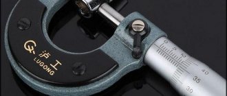
Typically, hardness testers have a part that affects the workpiece being tested. Examples include steel balls of various diameters and diamond tips with a pyramid shape. Let's take a closer look at some of the methods used today.
Rockwell hardness scales
Rockwell hardness tester dial
The standards standardize 11 scales for determining hardness using the Rockwell method (A; B; C; D; E; F; G; H; K; N; T), these scales differ in the type of indenter, test load and constants in the formula for calculating hardness based on the results measurements.
The two most widely used indenters are a 1/16 inch (1.5875 mm) spherical tungsten carbide or tool steel ball or 1/8 inch diameter ball and a conical diamond tip with a rounded tip angle of 120°. The standards provide, depending on the scale, 3 fixed loads when pressing the indenter - 60, 100 and 150 kgf.
The numerical value of hardness is determined by a formula, the coefficients of which depend on the scale. To reduce the measurement error depending on the state of the surface under test, the relative difference in the depth of penetration of the indenter is taken when applying the main and preliminary (10 kgf) load (see figure).
To denote hardness determined by the Rockwell method, the abbreviation HR is used, with a 3rd letter indicating the scale on which the tests were carried out (HRA, HRB, HRC, etc. to HRT).
For example, HRC 64. The most widely used Rockwell hardness scales
| Scale | Indenter | Load, kgf |
| A | Diamond cone with 120° apex angle | 60 |
| IN | 1/16" diameter tungsten carbide (or hardened steel) ball | 100 |
| WITH | Diamond cone with 120° apex angle | 150 |
Formulas for determining hardness
The harder the material, the less depth the tip will penetrate into it. To ensure that a higher hardness of the material does not result in a lower Rockwell hardness number, the hardness is determined by the formula:
HR=N−H−hs{\displaystyle HR=N-{\frac {Hh}{s}}} where the difference H−h{\displaystyle Hh} is the relative penetration depth of the indenter under preliminary and main loads in mm, N, {\displaystyle N,} s{\displaystyle s} are constants that depend on the specific Rockwell scale (see table).
Thus, Rockwell hardness is a dimensionless quantity.
Most commonly used Rockwell scales
| Scale | Abbreviation | Test load | Indenter type | Application area | N | s |
| A | HRA | 60 kgf | 120° diamond spheroconic* | Wolfram carbide | 100 | 0.002 mm |
| B | HRB | 100 kgf | Diameter 1⁄16" (1.588 mm) steel, spherical | Aluminum alloys, bronze, mild steels | 130 | 0.002 mm |
| C | H.R.C. | 150 kgf | 120° diamond, spheroconic | Hard steel HRB > 100 | 100 | 0.002 mm |
| D | HRD | 100 kgf | 120° diamond, spheroconic | 100 | 0.002 mm | |
| E | HRE | 100 kgf | Diameter 1⁄8" (3.175 mm) steel, spherical | 130 | 0.002 mm | |
| F | HRF | 60 kgf | Diameter 1⁄16" (1.588 mm) steel, spherical | 130 | 0.002 mm | |
| G | HRG | 150 kgf | Diameter 1⁄16" (1.588 mm) steel, spherical | 130 | 0.002 mm | |
| *Radius of spherical rounding of the cone apex 0.2 mm |
Links
This page was last edited on August 27, 2019 at 00:15.
Advantage of the Vickers method
The advantage of the Vickers method is the ability to measure the hardness of samples and small products made of hard alloys, ferrous and non-ferrous metals, thin sheet steels, hardened and non-hardened steels, castings, semi-precious and precious stones, galvanized, chrome-plated and tin-plated surface coatings of various thicknesses. Measuring hardness does not take much time (requires careful preparation of the surface being tested).
How is the Vickers hardness of test samples calculated?
After the test is completed, the lengths of the indentation diagonals are measured and, based on the average length, the hardness of the sample is calculated according to the tables (for more details, see GOST 2999-75).