Radio circuits. — Welding machine using powerful thyristors
materials in category
The proposed device is a direct current regulator, and since its adjustment range is very wide and uses powerful thyristors, it can be used both as a powerful charger and as a welding machine.
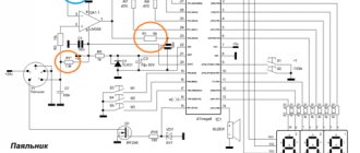
Diagram of a thyristor welding machine
A graph explaining the operation of a power unit made according to a single-phase bridge asymmetrical circuit (U2 is the voltage coming from the secondary winding of the welding transformer, alpha is the opening phase of the thyristor, t is time).
The regulator can be connected to any welding transformer with a secondary winding voltage U2=50…90V. The proposed design is very compact. The overall dimensions do not exceed the dimensions of a conventional unregulated bridge rectifier for DC welding. The regulator circuit consists of two blocks: control A and power B. Moreover, the first is nothing more than a phase-pulse generator. It is made on the basis of an analogue of a unijunction transistor, assembled from two semiconductor devices of npn and pnp types. Using variable resistor R2, the direct current of the structure is regulated. Depending on the position of the R2 slider, capacitor C1 is charged here to 6.9 V at different rates. When this voltage is exceeded, the transistors open sharply. And C1 begins to discharge through them and the winding of the pulse transformer T1. The thyristor, to the anode of which a positive half-wave approaches (the pulse is transmitted through the secondary windings), opens.
As a pulse one, you can use industrial three-winding TI-3, TI-4, TI-5 with a transformation ratio of 1:1:1. And not only these types. For example, good results are obtained by using two two-winding transformers TI-1 with a series connection of the primary windings. Moreover, all of the above types of TIs make it possible to isolate the pulse generator from the control electrodes of the thyristors.
There is only one “but”. The pulse power in the secondary windings of the TI is not sufficient to turn on the corresponding thyristors in the second (see diagram), power block B. An elementary way out of this “conflict” situation was found. To turn on the powerful ones, low-power thyristors with high sensitivity to the control electrode are used.
Power block B is made according to a single-phase bridge asymmetrical circuit. That is, the thyristors work here in one phase. And the arms on VD6 and VD7 work as a buffer diode during welding.
Installation? It can also be made mounted, based directly on the pulse transformer and other relatively “large-sized” circuit elements. Moreover, the radio components connected to this design are, as they say, minimum-minimorum.
The device starts working immediately.
Modeler-designer 1994 No. 9. A. CHERNOV, Saratov
radio-uchebnik.ru
General concepts
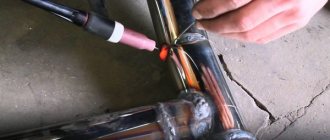
The principle of arc welding is well known. Let's refresh our memory of the basic concepts. To obtain a welding joint, an arc must be created. An electric arc occurs when voltage is applied between the welding electrode and the surface of the material being welded. The arc current melts the metal, forming a molten pool between the two ends. After the seam has cooled, we obtain a strong connection between the two metals.
Arc welding diagram.
In Russia, alternating current is regulated at a frequency of 50 Hz. Power for the welding machine is supplied from the mains with a phase voltage of 220 V. Welding transformers have two windings: primary and secondary. The secondary voltage of the transformer is 70 V.
Separate manual and automatic welding modes. In a home workshop, welding is carried out manually. We list the parameters that can be changed manually:
- welding current;
- arc voltage;
- welding electrode speed;
- number of passes per seam;
- diameter and brand of electrode.
The correct selection and maintenance of the necessary parameters throughout the welding process are the key to a high-quality welded joint..
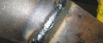
When carrying out manual arc welding, it is necessary to correctly distribute the current. This will allow you to make a high-quality seam. The stability of the arc directly depends on the magnitude of the welding current. Experts select it based on the diameter of the electrodes and the thickness of the materials being welded.
Power Electronics
kuzikovs wrote:
Yes, it’s too early to describe it actually
I think it’s just time! There’s less chance of mistakes!
kuzikovs wrote:
T2 8-line w-shaped gap what remained from the previous circuit 0.2 mm, if it is necessary at all, I still don’t understand, I protected the turns relative to the inductance using the formulas given by the author,
Yeah, and right here! Take your time, now I’ll find information on this issue from Tiran, who had problems with these cores, and then he found the reason and successfully did the same for them! You see, the description is right on time! I copy everything and after a while I will find and post a copy, the number of turns is specifically indicated there.
kuzikovs wrote:
He also left the protective nichrome and saved the shooting ranges from death, he also left a snubber chain parallel to the shooting ranges and removed the reverse diode.
Everything seems to be fine here, but it seems to me better to install reverse diodes, I agree with *Antek*, and even with the generator connected in this way, the circuit may not be predictable!?
Here *cuzikovs* found the necessary information for you! Good luck!
valvol.ru
How to make a homemade welding inverter using thyristors?
- Date: 08/17/2015
- Rating: 35
A homemade welding inverter is made using transistors and thyristors. Simple transistor devices are not reliable enough. Analogues with thyristors are able to withstand output short circuits until the fuse trips (in the absence of damage). An inverter based on thyristors heats up less during operation than a welding inverter based on transistors. The advantage of homemade devices is their simple design and the general availability of the necessary parts and materials.
Scheme of an inverter welding source.
{advertisement1}
Tool making instructions
Experts advise first familiarizing yourself with the equipment diagram. One of the main parts is a 6 mm duralumin plate, to which it is necessary to attach conductors with wires (without thermal insulation) that give off heat. To assemble a thyristor-based welding inverter, you will need the following tools and materials:
- radiator from a car;
- wires;
- seals;
- diodes;
- duralumin plate.
The radiator from the car will act as a fan, blowing air through the throttle and diodes. The choke is made of 6 copper cores and is pressed to the base using a seal. The diodes must be pressed to the base of the welding inverter circuit, attaching stabilizers and seals.
Table of required technical characteristics for a welding inverter.
You will need a transformer with a cross section of 2 mm and no insulation. The use of insulated cable is allowed. There are 4 wires in the conductor bundle. Insulating materials - electrical tape or fluoroplastic tape. It is necessary to leave a gap between the insulation layers (to cool the transformer).
The conductors must be spread apart for the welding inverter to function without failure. Then the power bridge is installed on the transistor. Use copper wire with a cross section of 2 mm. It must be wrapped with 2-3 layers of sewing thread. The conductor is fixed with insulating heels, to which the load from the transistors is transferred. A homemade welding inverter made according to this scheme is capable of working for a long time without interruption.
Manufacturing such equipment according to Negulyaev’s scheme requires pressing the transistors to the radiator. They are installed using duralumin plates and secured with small screws. Power bridges blown by fans are insulated so that there is no need to connect transistors to the bridges and radiator. Experts recommend taking into account the resonant voltage. The secondary winding (if necessary) is output to the power receiver or to the cylinders. The energy from the receiver goes to the cores.
Pulse equipment
Tools for making welding equipment.
The manufacture of high-power equipment requires winding across the entire width of the frame (to increase the transformer’s resistance to external forces and voltage surges). To assemble this device you will need:
- seals;
- converter;
- copper tin;
- knife;
- insulating tape.
It is necessary to make several layers of the secondary winding of the device, and wind the inductor on a ferrite core.
The device will be cooled using a radiator from a computer, which corresponds to the equipment being manufactured in terms of electricity and power consumption.
It is undesirable to use aluminum wires for a generator because of their instability to alternating current fluctuations.
{advertisement2}
The operation of the unit depends on the following indicators:
- thickness of the wire used;
- use of alternating or direct current;
- transmission capacity from 30 to 160 A.
You can set up a homemade welding machine with the help of professionals or yourself. The generator must be connected to the network. The unit will begin to make loud noises when current is transferred. The resistor must be closed by connecting the relay after charging the capacitors. Transmittance is determined using a multimeter. The device needs to be switched to ammeter mode and the frequency of pulses is determined. The indicator should be 44%.
The generator is tested using an optocoupler and an amplifier. The average amplitude value for low-power devices is 15 V. Then it is necessary to check the power bridge assembly by supplying 16 V power to the device. At idle, a conversion of up to 100 mA is recorded. Measurements will not be accurate if these recommendations are not followed.
https://moyasvarka.ru/youtu.be/LvIyLUOzS64
The operation of the generator is checked with an oscilloscope. The pulses emanating from the windings must match. The transformer is controlled by capacitor control. It is necessary to increase the throughput level to 200 V, connect the inverter to an oscilloscope and monitor the shape of the incoming signal coming from the emitter collector.
moyasvarka.ru
Semiconductors in a current control circuit
Figure 1. Diagram of the welding current regulator.
Semiconductor devices have made a real breakthrough in welding. Modern circuit technology allows the use of powerful semiconductor switches. Thyristor circuits for adjusting welding current are especially common. The use of semiconductor devices is replacing inefficient control circuits. These solutions increase the limits of current regulation. Large and heavy welding transformers containing huge amounts of expensive copper have been replaced with light and compact ones.
An electronic thyristor regulator is an electronic circuit necessary to control and adjust the voltage and current that are supplied to the electrode at the welding site.
For example, consider a thyristor-based regulator. The diagram of the welding current regulator is shown in Fig. 1.
The circuit is based on the principle of a phase current regulator.
The adjustment is carried out by applying control voltage to solid-state relays - thyristors. Thyristors VS1 and VS2 open alternately when signals arrive at the control electrodes. The supply voltage of the control pulse generation circuit is removed from a separate winding. Next it is converted to DC voltage by a diode bridge on VD5-VD8.
The positive half-wave charges capacitance C1. The charging time of the electrolytic capacitor is formed by resistors R1, R2. When the voltage reaches the required value (more than 5.6 V), the dinistor formed by the zener diode VD6 and thyristor VS3 opens. The signal then passes through the diode VD3 or VD4. With a positive half-wave, thyristor VS1 opens, with a negative half-wave, VS2 opens. Capacitor C1 will discharge. After the start of the next half-cycle, thyristor VS1 closes and the capacitor is charged. At this moment, key VS2 opens, which continues to supply voltage to the electric arc.
The setup comes down to setting the welding current range using the trimmer resistance R1. As you can see, the welding current adjustment scheme is quite simple. The availability of the element base, ease of setup and control of the regulator allow the manufacture of such a welding machine independently.
Inverter welding machines
The device of an inverter welding machine.
Inverters occupy a special place among welding equipment. An inverter welding machine is a device that can provide stable power to the welding arc. Small dimensions and light weight make the device mobile. The strength of the inverter is the ability to use AC and DC electrodes. Welding allows you to join non-ferrous metals and cast iron.
The main advantages of using an inverter:
- protection against heating of parts;
- resistance to network disturbances;
- independence from fluctuations and current overloads;
- independence from industrial network fluctuations;
- ability to bond non-ferrous metals;
- welding current stability;
- high-quality seam;
- smooth arc burning;
- light weight and dimensions.
The disadvantages of welding inverters include high cost. Electronic parts should be protected from moisture, dust, heat and severe frost (below 15 o C).
Inverter welding equipment today is present in almost all locksmith and auto repair shops.
WELDING MACHINE
Recently I talked with my teacher at the university, and to my misfortune, I revealed my amateur radio talents. In general, the conversation ended with the fact that I undertook to assemble a man a thyristor rectifier with a smooth current regulator for his welding “donut”. Why is this necessary? The fact is that alternating voltage cannot be welded with special electrodes designed for constant use, and given that welding electrodes come in different thicknesses (most often from 2 to 6 mm), the current value must be proportionally changed.
When choosing a welding regulator circuit, I followed the advice of -igRomana- and settled on a fairly simple regulator, where the current is changed by applying pulses to the control electrodes, generated by an analogue of a powerful dinistor, assembled on a KU201 thyristor and a KS156 zener diode. See the diagram below: