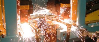
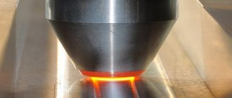
Seam resistance welding technology was developed at the end of the 19th century. Welding is carried out without a consumable electrode and filler material. Heating and melting of a small area of workpieces occurs due to a high-intensity electrical discharge periodically passed between two roller electrodes, to which a significant compression force is applied. The weld consists of many overlapping fusion zones. The method is intended for welding thin sheet metal, including those with complex spatial shapes.
Description of seam welding technology
Sheet blanks are placed on top of each other and compressed by roller electrodes with great force. Powerful current pulses are periodically applied to the electrodes, the strength of which reaches thousands of amperes. The flowing current strongly heats the contact spot between the electrodes, bringing the metal to melting. At the end of the pulse, the melting zone crystallizes under strong pressure, forming a suture material and connecting the workpieces into a single whole. The rollers roll onto the adjacent section of the workpiece, the next impulse is applied and the working cycle is repeated. A chain of oval-shaped resistance spot welding spots is formed along the seam line. These spots may partially overlap to form a continuous and sealed suture line.
Depending on the type of movement of parts and the method of supplying current pulses, resistance seam welding is divided into:
- Stepper. The pressure of the rollers is constant, the parts move jerkily, and when they stop, a working impulse is given. The result is an intermittent chain of points welded using the contact method. It is used for welding non-ferrous alloys and light metals. Does not ensure the tightness of the suture material.
- Continuous. The pressing force is constant, the current is also supplied constantly. In practice, it is rarely used due to the rapid consumption of rollers, high power consumption and overheating of the welded parts, leading to their warping.
- Intermittent. The clamping force remains unchanged, and the feed speed of the workpieces is also constant. Pulses are applied at intervals in order to ensure a continuous seam line due to partial overlap of spot welding zones.
Seam welding diagram (working principle)
Intermittent contact seam roller welding allows you to obtain a reliable and leak-tight seam joint at an acceptable consumption of rollers and electricity. The degree of overlap of the welded zones is adjusted by adjusting the duty cycle (repetition period) of the pulses. This seam welding technology has become most widespread. Requirements for the operation are described in the GOST 15878-79 standard.
Quality control of welded joints
Welding quality control during seam and resistance spot welding is especially important, since the process proceeds very quickly and the nature of the formation of the joint is hidden from external observation. Various factors can lead to the formation of defects in a weld, such as lack of penetration. This includes the condition of the surfaces of parts and electrodes, the quality of assembly, and the variability of welding modes. In addition to lack of penetration, hot cracks, metal splashes and pitting may occur during welding.
Lack of penetration poses the greatest danger; they significantly reduce the performance characteristics of the connection, such as strength and tightness. External and internal metal splashes worsen the appearance of the product and can clog the lines. Cracks and cavities can mainly affect the tightness and, to a lesser extent, the strength, since they are located outside the zone of greatest operating stress.
When resistance welding, comprehensive control of joints is usually used, starting from monitoring equipment, fixtures, the condition of the surfaces of parts and electrodes, checking the quality of assembly and ending with monitoring the welded joint itself.
Control of the finished welded joint is a rather difficult task in resistance welding. For this purpose, the radiographic method of X-ray control is used. Using this non-destructive testing method, cracks, cavities, and splashes can be clearly identified.
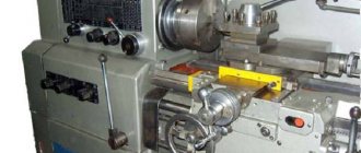
Contact welding machines and machines
Bronze is most often used for roller electrodes. They are made in the form of pointed disks with a diameter of 35-45 cm, the width of the working rim is 4-10 mm. For welding complex workpieces, machines with two or more roller pairs are used.
The power consumption of the devices varies from 25 to 300 kilowatts.
Low-power machines are considered to be 25-40 kilowatts, average power is 4-100, high-power machines consume from 100 to 300.
The medium power device MSh-2203 requires a three-phase power supply of 380 volts, an operating current of up to 22 thousand amperes. The clamping force reaches 5 tons
The resistance seam welding machine welds steel sheets up to 1 mm thick. There are two modifications - with a roller reach of 400 and 700 mm.
Contact welding. Essence and main types
Topic 3.4.1 Contact welding. Essence and main types
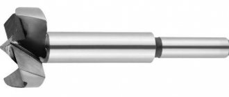
Fig.90 RDM-2-66 cutter for plasma-arc cutting
For manual plasma cutting, a RDM-2-66 plasma torch is used (Fig. 90). The plasma torch consists of a head 4, a mouthpiece with a forming nozzle 3 and a handle 5. The cutter head 4 has a water-cooled body, to which water is supplied and discharged through sleeves 8. The mouthpiece is insulated from the current-carrying body with a rubber gasket. The valve-valve block, mounted on the handle, consists of a valve for supplying argon 10 with fitting 9, a lever valve 6, which allows cutting in a mixture of argon with hydrogen or nitrogen, and fitting 7. The cutter has a support roller 2 and a shield 1. In the cable The hose package includes two gas hoses - for argon and hydrogen or nitrogen and two water cooling hoses. In one of the cooling sleeves there is an operating current cable with a cross-section of 10 mm2, which is connected to the minus of the power source.
The RDM-2-66 plasma torch is designed for manual separation cutting of aluminum and its alloys up to 25 mm thick and stainless steels up to 20 mm thick. Cutting is performed in an argon-hydrogen or argon-nitrogen mixture using direct current of direct polarity.
Questions:
2. The essence, application and technology of resistance and flash butt welding, one- and two-sided spot welding, seam welding with continuous and intermittent current.
3. Equipment for resistance welding; main parts and operating principle of contact machines.
1. According to GOST 2601–84, contact welding is called welding using pressure, in which heating is carried out by heat generated when an electric current passes through the parts being connected. At the point where the parts come into contact, the current experiences great resistance, which causes a significant amount of heat to be released, heating the metal so much that it becomes plastic or melts. In this case, the parts of the workpieces to be welded are strongly pressed against one another.
Metals with low electrical resistance, such as copper and aluminum, are more difficult to resistance weld than steel, which has a higher electrical resistance.
Rice. 91 Resistance welding:
a – butt; b – point; c – suture; 1 and 2 – parts to be welded; 3 – copper electrodes; 4 – weld; 5 – welding transformer
Resistance welding is divided into flash butt, resistance butt, spot, seam, relief, etc.
In butt contact welding (Fig. 91, a), the connection of the welded parts occurs along the surface of the butt ends. This method is used to weld pipes, rails, chains, the drill part of which is made of high-speed steel, and the shank is made of carbon steel, etc.
In spot resistance welding (Fig. 91, b), the connection of elements occurs in areas limited by the area of the ends of the electrodes that supply current and transmit compression force. Electrodes are made hollow from alloys of copper with chromium, aluminum and other elements. During welding, they are cooled by water circulating in the cavity. Spot welding is used in the manufacture of cabins, bodies and grain containers, cladding parts and other products from rolled sheet metal in the automotive and agricultural engineering industries.
In seam resistance welding (Fig. 91, c), the elements are overlapped with rotating disk electrodes. The seam can be continuous or intermittent. Fuel tanks, for example, are produced using resistance seam welding with continuous seams. Resistance welding is highly productive and is widely used in many industries in serial and mass production.
2. Butt welding is divided into flash welding and resistance welding.
Reflow welding
the ends of the workpieces are brought to melting, and during resistance welding, the ends of the workpieces are heated to a plastic state and subsequent upsetting is carried out.
Welded parts 3
and
7
(Fig. 92) are placed between terminals
4
and
6
connected to the secondary winding of transformer
8
.
One of the plates 2
is fixedly fixed on the frame
1
and isolated from it, and the other plate
5
can be moved along the guides of the frame. The movement of the plate together with the fixed part is carried out in machines using a lever, steering wheel, spring, and when welding parts of large sizes - using mechanical, hydraulic or pneumatic devices.
When resistance welding
workpieces clamped in the machine are compressed with a slight force, ensuring contact of the welded surfaces.
Then the current is turned on, the metal is heated to a plastic state, and upsetting and welding are performed. The welding site has metal reinforcement (upsetting). Before welding Fig.
92 blanks are cleaned and adjusted one to another. Resistance welding is used mainly for workpieces of small cross-section (diameter up to 20 mm), since when welding rods of large cross-sections, heating across the cross-section will be uneven. The sections of the workpieces to be joined must be identical in shape with a poorly developed perimeter (circle, square, rectangle with a small aspect ratio). Blanks of a more complex cross-section (sheet, thin-walled pipe, I-beam, square), as well as blanks made of dissimilar metals, are not paired using the mime method.
The fusion method has a number of advantages over resistance welding, the main of which are the following: the joint surface does not require special preparation; it is possible to weld workpieces with a cross-section of complex shape and a highly developed perimeter, as well as workpieces with different sections; dissimilar metals are welded (high-speed and carbon steel, copper and aluminum, etc.). The disadvantage of flash welding is that the material consumption increases. This is especially noticeable when using expensive metals.
When spot welding, workpieces made of thin sheet metal (0.2...8 mm thick) are overlapped.
The spot welding method consists of heating the parts being welded by passing current from one electrode through the parts to another. Rapid heating and melting of the metal occurs in the joint zone with the formation of a “core” of a welding point, which has a lenticular shape, usually 2…12 mm in size. Pressure P
, applied to the electrodes, compacts the metal at the welding point and ensures a strong connection.
In Fig. Figure 93 shows a spot welding diagram. Weldable sheets 4
clamped between the upper
3
and lower
5
electrodes of the welding machine, to which
current from the transformer
8
2
and
6
and trunks
1
and
7. The lower support trunk is made stationary, and the upper one is movable; When welding, the upper trunk creates pressure on the sheets being welded. The surfaces of the workpieces being welded in contact with the copper electrode heat up more slowly than their internal layers. Heating is continued until the plastic state or partially until the internal layers of the part melt, then the current is turned off and the pressure is reduced. As a result, a cast weld point is formed.
Spot welding, depending on the location of the electrodes in relation to the parts being welded, can be double-sided or single-sided. Rice. 93
Single-sided spot welding
You can connect workpieces simultaneously with two points. Multi-spot machines operate on the principle of one-sided spot welding, which can have up to 50 pairs of electrodes.
To obtain a good quality connection, it is necessary to strictly adhere to the specified mode parameters: compression force from 2 to 10 kgf/mm2, current flow time 0.01...1.5 s. Pre-welded surfaces are cleaned with an emery wheel, sandblasting or etching.
Spot welding can also be carried out in harsh conditions. Soft modes are characterized by longer welding times, smooth heating, and reduced power. These modes are used for welding carbon, structural, low-alloy steels and steels prone to hardening. The values of the main parameters of soft modes can be changed in the following ranges: current density - from 80 to 160 A/mm2; the force on the electrodes is from 1.5 to 4 kgf/mm2 and the current flow time is from 0.5 to 2...3 s.
Hard modes are characterized by increased productivity due to reduced welding time, increased compression force and concentrated heating. These modes are used: a) for welding stainless steels, since when welding in soft modes, precipitation of carbides in the heat-affected zone is possible, leading to loss of corrosion resistance; b) for welding aluminum, honey and copper alloys, since they have high thermal conductivity and overheating of the heat-affected zone is unacceptable for them; c) for welding ultra-thin metal up to 0.1 mm thick.
The thickness limits of welded metals are on average 0.5...5 mm. Spot welding is widely used for the manufacture of stamped joints, where individual stamped parts are connected by welded spots. In this case, the manufacturing technology of welded assemblies is simplified and productivity increases.
A sign of seam welding is the presence of at least one electrode in the form of a roller rolling along the seam. Roller welding is a type of spot welding in which the core points overlap one another and create a continuous seam; a strong and tight connection is formed between the workpieces being welded. When seam welding (Fig. 94), parts to be welded 1
also overlapped and placed between two rotating copper rollers (electrodes)
2
, through which current flows from the transformer
3
to heat and melt the metal.
These same rollers produce upsetting (compression) of the heated metal as it moves along the seam. The thickness of the sheets being welded should be on average 0.3...3 mm. Seam welding, like spot welding, can be performed with one-sided or two-sided arrangement Fig.
94 electrodes (rollers).
There are two seam welding cycles: with continuous and intermittent current flow
.
The first cycle is used for welding short seams made of low-carbon and low-alloy steels up to 1 mm thick; when welding long seams, the rollers may overheat. In addition, with minor changes in the cleanliness of the metal surface, burns or lack of penetration occur. When current is continuously passed, a large heat-affected zone is formed, which can lead to warping of parts.
The second cycle ensures process stability and high quality of the welded joint with a small heat-affected zone; it applies
for welding long seams on workpieces made of stainless steel, aluminum and copper alloys.
Seam welding is used in mass production in the manufacture of various vessels. Short seams are welded from one end to the other, and long seams are welded from the middle to the ends. Roller welding is carried out using alternating current with a power of 2000...5000 A. The diameter of the rollers is 40...350 mm; The compression force of the parts being welded by the rollers reaches 0.6 t; welding speed is 0.5...3.5 m/min.
There are various designs of seaming machines, differing in the location of the rollers. In machines for longitudinal welding, the rollers rotate along the consoles of the machine, and in machines for transverse welding, the rollers rotate in a plane perpendicular to the axis of the consoles.
3.The manufacture of products by resistance butt welding is performed on universal or specialized butt welding machines.
The butting machine has the following main components and elements (Fig. 95): frame 2, fixed plate 4, movable plate 8, which moves along guides 10 by feed drive 9, clamping devices 7, transformer 1, current leads 3, jaws 5 and control equipment P.
Fig.95 Design diagram of a butting machine
To manufacture products using the resistance spot welding method, a spot welding machine MTP-200-7 is used (Fig. 96), which must provide compression of the parts with a certain force and supply welding current to them.
Fig. 11 Diagram of the MTP-200-7 dot machine:
1 – body; 2 – welding transformer; 3 – compression drive; 4 – consoles; 5 – electrode holders; 6 – electrodes; 7 – details; 8 – strut; 9 – bracket (holder); 10 – flexible tires; 11 – secondary turn of the transformer
It has a corresponding compression drive 3
(Fig. 96) and current source
2.
Structural elements of machines: consoles
4,
electrode holders, electrodes, housing, brackets, struts. They perceive significant forces from the compression drive and thermal expansion of the metal in the welding zone. Some of them, included in the secondary circuit of the machine, simultaneously serve as current-carrying elements.
To manufacture products by seam (roller) welding in large-scale production, a seam welding machine MShPR-300-1200 is used (Fig. 97).
Fig. 97 Diagram of the MShPR-300-1200 seaming machine:
1 – body; 2 – welding transformer; 3 – compression drive; 4 – consoles; 5 – rollers; 6 – details; 7 – bracket (holder); 8 – flexible tires; 9 – secondary turn of the transformer; 10 – roller rotation drive
This machine must provide compression of parts with a certain force and supply welding current to them. Seam welding machines typically move parts by point increments. Therefore, they have a roller rotation drive (Fig. 9). The structural elements of the machine are consoles 4,
compression drive, rollers, housing, brackets, flexible tires. They perceive significant forces from the compression drive and thermal expansion of the metal in the welding zone. Some of them, included in the secondary circuit of the machine, simultaneously serve as conductive elements.
Current sources.
Contact machines operate on alternating current (from thousands to one hundred thousand amperes). The electrical circuit of current sources of all types of contact machines consists of three elements: a transformer, a breaker and a power step switch. The primary winding of the transformer is connected to a network with voltage from 220 to 380 V; it is made sectional to change the number of working turns when switching power levels. The secondary winding of the transformer consists of one or two turns (secondary voltage from 1 to 12 V).
Current breakers.
To turn the welding current on and off, several types of breakers are used: simple mechanical contactors, electromagnetic (synchronous and asynchronous), electronic devices (thyratron and ignitron).
Mechanical contactors are used mainly on low-power non-automatic point-to-point machines. Electromagnetic contactors are used for butt, spot and seam welding on low and medium power machines. Electronic breakers provide synchronous switching on and off of current with a strictly defined duration of current pulses and pauses and are used for all types of automatic contact machines.
Pressure mechanisms
can be lever-pedal, motor-cam, with pneumatic or hydraulic pressure drives. The pressure mechanism serves to compress the workpieces.
Topic 3.4.1 Contact welding. Essence and main types
Fig.90 RDM-2-66 cutter for plasma-arc cutting
For manual plasma cutting, a RDM-2-66 plasma torch is used (Fig. 90). The plasma torch consists of a head 4, a mouthpiece with a forming nozzle 3 and a handle 5. The cutter head 4 has a water-cooled body, to which water is supplied and discharged through sleeves 8. The mouthpiece is insulated from the current-carrying body with a rubber gasket. The valve-valve block, mounted on the handle, consists of a valve for supplying argon 10 with fitting 9, a lever valve 6, which allows cutting in a mixture of argon with hydrogen or nitrogen, and fitting 7. The cutter has a support roller 2 and a shield 1. In the cable The hose package includes two gas hoses - for argon and hydrogen or nitrogen and two water cooling hoses. In one of the cooling sleeves there is an operating current cable with a cross-section of 10 mm2, which is connected to the minus of the power source.
The RDM-2-66 plasma torch is designed for manual separation cutting of aluminum and its alloys up to 25 mm thick and stainless steels up to 20 mm thick. Cutting is performed in an argon-hydrogen or argon-nitrogen mixture using direct current of direct polarity.
Questions:
2. The essence, application and technology of resistance and flash butt welding, one- and two-sided spot welding, seam welding with continuous and intermittent current.
3. Equipment for resistance welding; main parts and operating principle of contact machines.
1. According to GOST 2601–84, contact welding is called welding using pressure, in which heating is carried out by heat generated when an electric current passes through the parts being connected. At the point where the parts come into contact, the current experiences great resistance, which causes a significant amount of heat to be released, heating the metal so much that it becomes plastic or melts. In this case, the parts of the workpieces to be welded are strongly pressed against one another.
Metals with low electrical resistance, such as copper and aluminum, are more difficult to resistance weld than steel, which has a higher electrical resistance.
Rice. 91 Resistance welding:
a – butt; b – point; c – suture; 1 and 2 – parts to be welded; 3 – copper electrodes; 4 – weld; 5 – welding transformer
Resistance welding is divided into flash butt, resistance butt, spot, seam, relief, etc.
In butt contact welding (Fig. 91, a), the connection of the welded parts occurs along the surface of the butt ends. This method is used to weld pipes, rails, chains, the drill part of which is made of high-speed steel, and the shank is made of carbon steel, etc.
In spot resistance welding (Fig. 91, b), the connection of elements occurs in areas limited by the area of the ends of the electrodes that supply current and transmit compression force. Electrodes are made hollow from alloys of copper with chromium, aluminum and other elements. During welding, they are cooled by water circulating in the cavity. Spot welding is used in the manufacture of cabins, bodies and grain containers, cladding parts and other products from rolled sheet metal in the automotive and agricultural engineering industries.
In seam resistance welding (Fig. 91, c), the elements are overlapped with rotating disk electrodes. The seam can be continuous or intermittent. Fuel tanks, for example, are produced using resistance seam welding with continuous seams. Resistance welding is highly productive and is widely used in many industries in serial and mass production.
2. Butt welding is divided into flash welding and resistance welding.
Reflow welding
the ends of the workpieces are brought to melting, and during resistance welding, the ends of the workpieces are heated to a plastic state and subsequent upsetting is carried out.
Welded parts 3
and
7
(Fig. 92) are placed between terminals
4
and
6
connected to the secondary winding of transformer
8
.
One of the plates 2
is fixedly fixed on the frame
1
and isolated from it, and the other plate
5
can be moved along the guides of the frame. The movement of the plate together with the fixed part is carried out in machines using a lever, steering wheel, spring, and when welding parts of large sizes - using mechanical, hydraulic or pneumatic devices.
When resistance welding
workpieces clamped in the machine are compressed with a slight force, ensuring contact of the welded surfaces.
Then the current is turned on, the metal is heated to a plastic state, and upsetting and welding are performed. The welding site has metal reinforcement (upsetting). Before welding Fig.
92 blanks are cleaned and adjusted one to another. Resistance welding is used mainly for workpieces of small cross-section (diameter up to 20 mm), since when welding rods of large cross-sections, heating across the cross-section will be uneven. The sections of the workpieces to be joined must be identical in shape with a poorly developed perimeter (circle, square, rectangle with a small aspect ratio). Blanks of a more complex cross-section (sheet, thin-walled pipe, I-beam, square), as well as blanks made of dissimilar metals, are not paired using the mime method.
The fusion method has a number of advantages over resistance welding, the main of which are the following: the joint surface does not require special preparation; it is possible to weld workpieces with a cross-section of complex shape and a highly developed perimeter, as well as workpieces with different sections; dissimilar metals are welded (high-speed and carbon steel, copper and aluminum, etc.). The disadvantage of flash welding is that the material consumption increases. This is especially noticeable when using expensive metals.
When spot welding, workpieces made of thin sheet metal (0.2...8 mm thick) are overlapped.
The spot welding method consists of heating the parts being welded by passing current from one electrode through the parts to another. Rapid heating and melting of the metal occurs in the joint zone with the formation of a “core” of a welding point, which has a lenticular shape, usually 2…12 mm in size. Pressure P
, applied to the electrodes, compacts the metal at the welding point and ensures a strong connection.
In Fig. Figure 93 shows a spot welding diagram. Weldable sheets 4
clamped between the upper
3
and lower
5
electrodes of the welding machine, to which
current from the transformer
8
2
and
6
and trunks
1
and
7. The lower support trunk is made stationary, and the upper one is movable; When welding, the upper trunk creates pressure on the sheets being welded. The surfaces of the workpieces being welded in contact with the copper electrode heat up more slowly than their internal layers. Heating is continued until the plastic state or partially until the internal layers of the part melt, then the current is turned off and the pressure is reduced. As a result, a cast weld point is formed.
Spot welding, depending on the location of the electrodes in relation to the parts being welded, can be double-sided or single-sided. Rice. 93
Single-sided spot welding
You can connect workpieces simultaneously with two points. Multi-spot machines operate on the principle of one-sided spot welding, which can have up to 50 pairs of electrodes.
To obtain a good quality connection, it is necessary to strictly adhere to the specified mode parameters: compression force from 2 to 10 kgf/mm2, current flow time 0.01...1.5 s. Pre-welded surfaces are cleaned with an emery wheel, sandblasting or etching.
Spot welding can also be carried out in harsh conditions. Soft modes are characterized by longer welding times, smooth heating, and reduced power. These modes are used for welding carbon, structural, low-alloy steels and steels prone to hardening. The values of the main parameters of soft modes can be changed in the following ranges: current density - from 80 to 160 A/mm2; the force on the electrodes is from 1.5 to 4 kgf/mm2 and the current flow time is from 0.5 to 2...3 s.
Hard modes are characterized by increased productivity due to reduced welding time, increased compression force and concentrated heating. These modes are used: a) for welding stainless steels, since when welding in soft modes, precipitation of carbides in the heat-affected zone is possible, leading to loss of corrosion resistance; b) for welding aluminum, honey and copper alloys, since they have high thermal conductivity and overheating of the heat-affected zone is unacceptable for them; c) for welding ultra-thin metal up to 0.1 mm thick.
The thickness limits of welded metals are on average 0.5...5 mm. Spot welding is widely used for the manufacture of stamped joints, where individual stamped parts are connected by welded spots. In this case, the manufacturing technology of welded assemblies is simplified and productivity increases.
A sign of seam welding is the presence of at least one electrode in the form of a roller rolling along the seam. Roller welding is a type of spot welding in which the core points overlap one another and create a continuous seam; a strong and tight connection is formed between the workpieces being welded. When seam welding (Fig. 94), parts to be welded 1
also overlapped and placed between two rotating copper rollers (electrodes)
2
, through which current flows from the transformer
3
to heat and melt the metal.
These same rollers produce upsetting (compression) of the heated metal as it moves along the seam. The thickness of the sheets being welded should be on average 0.3...3 mm. Seam welding, like spot welding, can be performed with one-sided or two-sided arrangement Fig.
94 electrodes (rollers).
There are two seam welding cycles: with continuous and intermittent current flow
.
The first cycle is used for welding short seams made of low-carbon and low-alloy steels up to 1 mm thick; when welding long seams, the rollers may overheat. In addition, with minor changes in the cleanliness of the metal surface, burns or lack of penetration occur. When current is continuously passed, a large heat-affected zone is formed, which can lead to warping of parts.
The second cycle ensures process stability and high quality of the welded joint with a small heat-affected zone; it applies
for welding long seams on workpieces made of stainless steel, aluminum and copper alloys.
Seam welding is used in mass production in the manufacture of various vessels. Short seams are welded from one end to the other, and long seams are welded from the middle to the ends. Roller welding is carried out using alternating current with a power of 2000...5000 A. The diameter of the rollers is 40...350 mm; The compression force of the parts being welded by the rollers reaches 0.6 t; welding speed is 0.5...3.5 m/min.
There are various designs of seaming machines, differing in the location of the rollers. In machines for longitudinal welding, the rollers rotate along the consoles of the machine, and in machines for transverse welding, the rollers rotate in a plane perpendicular to the axis of the consoles.
3.The manufacture of products by resistance butt welding is performed on universal or specialized butt welding machines.
The butting machine has the following main components and elements (Fig. 95): frame 2, fixed plate 4, movable plate 8, which moves along guides 10 by feed drive 9, clamping devices 7, transformer 1, current leads 3, jaws 5 and control equipment P.
Fig.95 Design diagram of a butting machine
To manufacture products using the resistance spot welding method, a spot welding machine MTP-200-7 is used (Fig. 96), which must provide compression of the parts with a certain force and supply welding current to them.
Fig. 11 Diagram of the MTP-200-7 dot machine:
1 – body; 2 – welding transformer; 3 – compression drive; 4 – consoles; 5 – electrode holders; 6 – electrodes; 7 – details; 8 – strut; 9 – bracket (holder); 10 – flexible tires; 11 – secondary turn of the transformer
It has a corresponding compression drive 3
(Fig. 96) and current source
2.
Structural elements of machines: consoles
4,
electrode holders, electrodes, housing, brackets, struts. They perceive significant forces from the compression drive and thermal expansion of the metal in the welding zone. Some of them, included in the secondary circuit of the machine, simultaneously serve as current-carrying elements.
To manufacture products by seam (roller) welding in large-scale production, a seam welding machine MShPR-300-1200 is used (Fig. 97).
Fig. 97 Diagram of the MShPR-300-1200 seaming machine:
1 – body; 2 – welding transformer; 3 – compression drive; 4 – consoles; 5 – rollers; 6 – details; 7 – bracket (holder); 8 – flexible tires; 9 – secondary turn of the transformer; 10 – roller rotation drive
This machine must provide compression of parts with a certain force and supply welding current to them. Seam welding machines typically move parts by point increments. Therefore, they have a roller rotation drive (Fig. 9). The structural elements of the machine are consoles 4,
compression drive, rollers, housing, brackets, flexible tires. They perceive significant forces from the compression drive and thermal expansion of the metal in the welding zone. Some of them, included in the secondary circuit of the machine, simultaneously serve as conductive elements.
Current sources.
Contact machines operate on alternating current (from thousands to one hundred thousand amperes). The electrical circuit of current sources of all types of contact machines consists of three elements: a transformer, a breaker and a power step switch. The primary winding of the transformer is connected to a network with voltage from 220 to 380 V; it is made sectional to change the number of working turns when switching power levels. The secondary winding of the transformer consists of one or two turns (secondary voltage from 1 to 12 V).
Current breakers.
To turn the welding current on and off, several types of breakers are used: simple mechanical contactors, electromagnetic (synchronous and asynchronous), electronic devices (thyratron and ignitron).
Mechanical contactors are used mainly on low-power non-automatic point-to-point machines. Electromagnetic contactors are used for butt, spot and seam welding on low and medium power machines. Electronic breakers provide synchronous switching on and off of current with a strictly defined duration of current pulses and pauses and are used for all types of automatic contact machines.
Pressure mechanisms
can be lever-pedal, motor-cam, with pneumatic or hydraulic pressure drives. The pressure mechanism serves to compress the workpieces.
Machine design for seam contact welding
The main supporting structure of the device is the frame. All other components are attached to it:
- power supply;
- fixed roller bracket;
- movable roller bracket;
- clamping device;
- workpiece feed mechanism
The clamping device can be manual, pneumatic, hydraulic or combined. The manual (more precisely, foot) drive has the least power.
The roller electrodes are made in the form of bronze disks tapering towards the edges; they are secured to the ends of the brackets using plain bearings.
Machine design for seam contact welding
The power source provides periodic supply of high power current to the electrodes. It also powers the drive of the clamping device and the feed mechanism. The power supply of modern devices is made using an inverter pulse circuit with double voltage conversion. This allows you to reduce the size of the device and eliminate voltage surges in the supply network.
Stitching machines
In addition to stationary welding machines, manufacturers also produce portable or hanging devices. They are designed for welding thin-walled products of complex configuration. The power source is still located on the workshop floor, and the rollers and clamping device are mounted on movable pliers. Using an articulated pneumatic drive, the pliers are installed in the position required for work.
Roller stand for contact welding
To weld structures in the shape of a cylinder (or a system of mating cylinders), roller stands are used. They are distinguished by a large overhang of the roller brackets, which makes it possible to weld fairly large and extended structures. The stand is equipped with a large number of adjustable supports, allowing you to secure cylindrical workpieces of different lengths and diameters. The roller electrodes are driven by a worm gear. The workpieces rotate on the stand, and thus the rollers pass the entire seam line. The stands produce smooth and sealed seams of high strength.
Roller stand for contact welding
Welding modes
The modes of seam intermittent (multi-pulse) welding of steels are given in table. XIII.16 and XIII.17; welding of aluminum alloys - in table. XIII.18.
Malyshev B.D. Welding and cutting in industrial construction vol.1. -M. 1989
See also: Resistance welding, Requirements for welded structures for spot and seam welding, Quality control of spot and seam welding joints, Industrial applications of spot and seam welding, Mechanization and automation of spot and seam welding
Application area
Seam contact welding technology allows you to make strong, durable and airtight seams that reliably connect thin-walled workpieces. It finds application in the following industries:
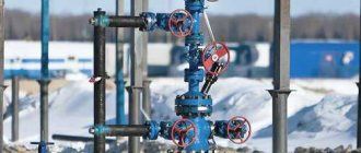
- Thin-walled welded pipes for pipeline transport and technological installations.
- Tanks and low pressure vessels for the chemical, food and transport industries.
- Sealed casings of mechanisms and devices, vehicles.
- Structures made of rolled sheets for industrial equipment and household appliances.
Production equipped with seam welding machines
The technology differs from other welding technologies in its greatest productivity. An average power unit produces several hundred meters of weld per hour.
With the light hand of Moscow manager Vasya Maksimov, metal-plastic pipes began to be divided into “seamless” and “seamless”. Without much thought, Vasily transferred his short experience of working at the Chelyabinsk metal warehouse into his marketing policy. This classification is essentially incorrect in relation to steel pipes, but in relation to metal-plastic pipes it is completely absurd. Nevertheless, the classification stuck.The division of metal-plastic pipes into “seamless” and “seamless” has given rise to a lot of nonsense in the marketing legends of managers, and still brings confusion into the minds of uninformed buyers.
Let's try to understand this issue and return common sense and a technological basis to the classification of metal-plastic pipes.
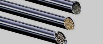
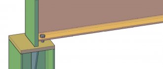
METAL-PLASTIC PIPES WITH ALUMINUM LAYER WELDED BUTT OR LAP
Of course, seamless metal-plastic pipes do not exist. And there are two basic technologies for the production of metal-plastic pipes: with the help of one of them, a metal-plastic pipe is produced with an aluminum pipe inside, the edges of which are overlap welded with ultrasound; in the other technology, the edges of the aluminum pipe are butt welded by TIG or laser welding. Those. There are welded seams in absolutely all metal-plastic pipes.
Construction of metal-plastic pipes
If the technologies are followed in both cases, pipes are obtained that meet the requirements of GOST R 53630-2009 , “Multilayer pressure pipes for water supply and heating systems” or DIN 16836, ISO 21003 standards. And in terms of their main characteristics: internal and external diameters, operating pressure and temperature of the pipe are analogues. And yet, there are a number of features due to differences in technology.
TWO TECHNOLOGIES OF METAL-PLASTIC PIPES
Metal-plastic pipes and the technology for their production were invented by the British in 1979. Then the small German company Unicor bought the technology from the British and became the owner of the WorldWide patent*. However, this technology is still called “English”.
* With the exception of Russia, in Russia the patent for the technology is owned by Extrusion Machines LLC
Thanks to sole ownership of the patent, Unicor has grown into a giant concern for the production of extrusion equipment, and a world leader in the market of metal-plastic pipes (brands Unipipe, Uponor). Currently, Unicor controls about 30% of the global market for metal-plastic pipes.
The essence of English technology is quite simple:
— an aluminum pipe is formed from aluminum tape;
— the edges of the formed pipe are overlap with ultrasound;
— almost simultaneously, internal and external layers of adhesive and polymer (PE - RT, PEX, PPR) are applied to the inner and outer surfaces of the aluminum pipe.
Due to the simultaneity of processes, the technology is sometimes called “combined”. The maximum achievable productivity with this technology is limited by the maximum achievable ultrasonic welding speed, and is currently around 25 meters per minute. The equipment is quite compact - the length of the lines is 25...45 meters.
English technology for the production of metal-plastic pipes
There are inventions whose simple and understandable principles have been part of everyday life for many years and retain undeniable competitive advantages: telephone, tape, ballpoint pen, CDs, microwave oven. Of course, English technology belongs to such inventions - no one has yet come up with pipes that combine the absence of corrosion, durability, low thermal expansion and absolute oxygen impermeability.
Perhaps the emergence of alternative technology is due to the severity of European and patent laws and Unicor's tough stance on technology dissemination.
An alternative technology was invented by the Swiss, and this was the only opportunity to enter the European market of extrusion equipment for the production of metal-plastic pipes.
Swiss technology made it possible to achieve higher productivity of 30...40 meters per minute, but it turned out to be quite cumbersome in essence and in terms of the size of the equipment - the length of the lines reaches 80...120 meters.
Swiss technology for the production of metal-plastic pipes
Due to the sequence of processes, the technology is sometimes called “separate”. A metal-plastic pipe using Swiss technology is produced in several stages:
— the internal polymer pipe is initially extruded;
— a melt of adhesive is applied to the outer surface of the resulting pipe;
— an aluminum pipe is formed around the resulting pipe from aluminum tape and “rolled” to the adhesive;
— the edges of the aluminum pipe are butt welded using laser or argon arc (TIG) welding;
— layers of adhesive and polymer are successively applied to the surface of the aluminum pipe.
As with English technology, the maximum productivity is limited by the capabilities of TIG and laser welding.
Currently, equipment using “English” technology is produced in Germany (Maintools) and Portugal (Fartrouven R&D), using “Swiss” technology - in Switzerland (Maillefer), Italy (Tecnomatic).
MYTHS ABOUT WELD STRENGTH
We owe the sales managers of “seamless” metal-plastic pipes the birth of myths that the strength of seamless pipes is much higher than that of “seamed” ones. This can be explained by the fact that the edges of the pipe are welded in the most “durable” way into a joint, the most reliable TIG (or laser welding), and by the fact that in a “seamless” pipe the aluminum layer is much thicker than in a “seamed” one.
The last statement is certainly true, and we will return to this later, but the strength of the weld is a vicious misconception.
Welding specialists are well aware that in overlap welding the strength of the weld is always higher than in butt welding.
Strength coefficients for various methods of welding an aluminum layer
If we take the strength coefficient of the foil as one, then when overlapping welding the strength coefficient will always be greater than one, and when butt welding it will always be less than one.
This is confirmed by the practice of testing and operating metal-plastic pipes - metal-plastic pipes with overlap welding never break at the seam, on the contrary, pipes with butt welding always break at the seam.
INSANE PROPERTIES OF A “SEAMLESS” WELD
There is another problem with “seamless” metal-plastic pipes. Sales managers usually do not know about this problem, or keep silent. This is the problem of weld brittleness in butt welding.
In English technology this problem does not exist, but in Swiss technology it is a chronically sore point.
The fact is that in the production of metal-plastic pipes, aluminum tape is used in a semi-soft condition in an annealed state (semi-hardened). At this condition, the aluminum tape is well formed and does not break at high production speeds. To achieve the required condition, aluminum producers anneal aluminum strip at temperatures of 350...380 C.
When lap welding with ultrasound, the weld zone is heated to relatively low temperatures of 0.3...0.5 the melting point of aluminum (about 198...330 degrees Celsius).
The joining process, in fact, is not welding in the usual sense, but is the process of the formation of diffusion interatomic bonds between two metal surfaces under the influence of ultrasound. Low heating in the weld zone does not change the mechanical condition of the aluminum, does not create internal stress at the joint, and does not impair the flexibility of the aluminum layer and the metal-plastic pipe itself as a whole.
Using Swiss technology, the aluminum layer is butt welded at temperatures much higher than the melting point of aluminum (i.e. more than 660 C). Of course, after welding, internal stress is generated in the weld zone.
Typically, a product welded using TIG or laser welding is annealed at temperatures of 350...380 C to eliminate stresses in the weld.
However, when producing a metal-plastic pipe, it is impossible to anneal the weld. At least, no one has invented such a method yet.
Another problem with Swiss technology with butt welding of an aluminum layer is also associated with high welding temperatures.
The temperature of thermal destruction of polymers currently used in the production of metal-plastic pipes (PE - RT and PEX polyethylene, PPR polypropylene) is in the range of 260...280 C.
Using Swiss technology, the aluminum layer is welded directly onto a fully formed inner plastic pipe, onto the surface of which a layer of melt adhesive is applied. At the same time, the high heating temperature of the weld causes local thermal destruction of the adhesive layer and the inner pipe itself in its zone. This negatively affects the strength of the metal-plastic pipe as a whole. And this is another reason for the typical rupture of a “seamless” pipe at the seam.
AGDESIA
The entire history of the evolution of metal-plastic pipes is closely related to the increase in resistance to delamination of its layers of metal and polymer.
In the early 80s of the last century, the adhesive strength between the layers of a metal-polymer pipe did not exceed 15 N/cm. This created problems when connecting metal-plastic pipes with mechanical fittings. Under the influence of long-term cyclic dynamic loads (temperature, pressure) at the junction with the fitting, the pipes delaminated and the tightness of the connection was broken.
Thanks to the developers of adhesives, resistance to delamination has now increased significantly, and in accordance with GOST R 53630-2009 it should be at least 50 N/cm. Most of the adhesives used meet these requirements, for example, Amplify G 388 (Dow Plastics), Plexar (Equistar), Yparex (DSM Group).
Typical Characteristics of Common Yparex
(Yparex BV (DSM Group)
Many developers are looking to increase adhesion in metal-plastic pipes, and we can expect that in the next 1.5...2 years, metal-plastic pipes with resistance to delamination at a level of 100...150 N/cm will appear on the market.
What is it for?
It is well known that any heterogeneous system is stronger, the higher the strength between its layers. Those. increasing the adhesive strength between the layers of metal and polymer in the pipe increases the strength of the metal-plastic pipes themselves, increases their durability, and allows you to create reliable and durable connections with fittings.
Resistance to delamination of metal-plastic pipes is mainly due to three factors:
— quality of aluminum surface cleaning:
— properties of adhesives;
— uniform application of the adhesive layer.
The quality of the aluminum surface and the properties of adhesives depend only on the technological capabilities of their manufacturers. But the uniformity of application of the adhesive layer on aluminum is different for the two technologies for the production of metal-plastic pipes.
Using English technology, the adhesive melt is extruded directly onto the inner and outer surfaces of the aluminum layer. In this case, bubbles do not appear in the adhesive layer, and stable resistance to delamination is ensured.
According to Swiss technology, there are also no problems with the outer layer; the melt is also extruded onto an aluminum layer.
Unevenness of the internal adhesive layer of a metal-plastic pipe using the technology of butt welding of an aluminum layer
But there is a systemic technological problem with the inner layer: it is practically impossible to roll aluminum tape onto a finished plastic pipe with an adhesive applied to its surface without bubbles. Those. It is practically impossible to achieve high adhesion between the inner plastic pipe and the aluminum layer.
.
COST FEATURES
A simple buyer of metal-plastic pipes can hardly worry about the cost issue. On the way from production to its purchase, many extra charges are added to the cost, behind which the cost itself is not visible. But if the question arises about organizing the production of multilayer metal-plastic pipes, it is necessary to take into account all the factors down to the last penny.
In metal-plastic pipes with an overlap-welded aluminum layer, rather thin aluminum foil is used, for example, in metal-plastic pipes with a diameter of 16 mm. foil with a thickness of 0.19…0.20 mm is used..
The strength of a 0.2 mm layer is quite sufficient to ensure low temperature expansion (0.25x10 -4), and the tensile strength of modern metal-plastic pipes has long crossed the GOST limit, for example, an overlap-welded metal-plastic pipe DEEPIPE type PERT - Al - PERT at a temperature of 95 C bursts at a pressure of 40...50 atm. (according to GOST, 13 is enough and thicker aluminum foil (tape) is used in pipes, this is due to the fact that it is impossible to butt weld thin foil using TIG or laser welding, and therefore even in pipes with a diameter of 16 mm, foil with a thickness of 0.35 is used... 0.4 mm..
It is quite obvious that differences in the thickness of the aluminum layer entail different costs of metal-plastic pipes. Knowing the geometry of the pipe, and it is determined by the standards, it is easy to calculate the cost of a meter of pipe for various manufacturing technologies.
To complete the picture, in the cost calculation, in addition to calculating the cost of materials, we took into account additional factors:
— Cost of equipment (a line with ultrasonic welding Fartrouven MCP/16-40 costs 940,000 EUR, a line with Tecnomatic butt welding costs 3,500,000 EUR);
— Occupied space (length Fartrouven MCP/16-40 — 32 m, Tecnomatic — 80 m);
— Salaries of operators (Fartrouven MCP/16-40 – 2 operators with low qualifications, Tecnomatic – 5 highly qualified operators).
Calculation of the cost of a metal-plastic pipe with a diameter of 16 mm.
The cost of a metal-plastic pipe with an aluminum layer butt welded is at least 30% higher than a pipe with an aluminum layer overlap welded.
Of course, to calculate the full cost, it is necessary to take into account general production, general business and marketing costs, and the cost of paying administrative and support personnel. Typically they amount to 23...30% of the above costs.
This means that production equipped with butt welding equipment will be able to compete with production based on ultrasonic welding equipment only if it does not have auxiliary production facilities, warehouses, offices, does not pay for telephones, transport, advertising, and does not have no other personnel except operators.
P. S.
Probably, in the near future, everyday disputes about “seamed” and “seamless” pipes, or butt-welded or overlapped, will become a thing of the past.
The modern consumer is less and less interested in technological and technical details. He is attracted by well-promoted brands and clear end results.
This means that manufacturers of metal-plastic pipes will have to thoughtfully choose technology and equipment for production, formulate a quality control policy, and hide it behind the moire of original marketing strategies, so that in a few years they do not lose the reputation of their brands and trust in the reliability of their products .
Sometimes it seems that creating an attractive brand is more difficult than creating a new technology.
In the coming years, we can expect that brand and consumer-friendly fittings will be the basis of competitive advantage...
| PRINTABLE OPTION |
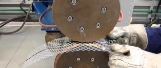
How to get a sealed seam
Seam tightness is ensured by creating a chain of partially overlapping resistance welding points. The weld spot after the pulse passed through the roller electrodes has the shape of an oval.
If you correctly combine the feed rate of the workpieces and the frequency of welding pulses, the ovals will overlap with their side parts, forming a continuous and sealed suture material.
Seam roller welding helps to make sealed containers and weld metal without surfacing materials. Accurate point connection can withstand heavy loads. Using special equipment, a sealed seam is obtained that does not allow liquids and gases to pass through. Roller technology, like all other types of welding, has its advantages and disadvantages. It is worth talking about them in detail. But first, a few words about the essence of the method of seam joining metal sheets.
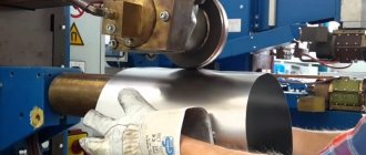
What is seam welding
Seam resistance welding is used to join sheet blanks. The metal is laid overlapping, and when current passes, the sheets are welded, forming a diffuse spot in the form of a point. The principle of roller welding is the same as that of contact welding. Only instead of conical conductive electrodes, disks made of bronze alloys are installed. They press the sheets against each other as they move. Electric current is supplied to the electrodes with varying regularity: continuously, intermittently or pulsed at a certain frequency. The essence of the method of roller resistance welding of sheet metal is the simultaneous heating and compression of parts in the weld area with roller electrodes. The metal melts under the action of a discharge and is compressed with such force that a homogeneous diffuse layer of high strength is formed.
A seam is essentially a dense series of points.
Industrial applications of spot and seam welding
Due to the high productivity and quality of welded joints, these welding methods are among the most promising, primarily in mass production conditions. Among mechanized welding methods, contact welding confidently takes first place. This welding is most widely used in the automotive industry. It finds no less application in carriage building, when connecting the car skin to the frame.
Other areas of mass application are the production of combines and tractors, household appliances, electronics, sports equipment and in construction for the manufacture of building panels and frames. Spot and seam welding occupies a special place in the manufacture of metal structures for critical purposes, for example, in the production of modern airliners.
In instrument making, this type of welding is used to produce sensitive elements, instrument housings, and relays. In electronics in the manufacture of terminals of integrated circuits, conductors, electron-optical systems.
Relief welding is used in the manufacture of reinforced concrete reinforcement, meshes, gratings, connections of fasteners and fittings, studs with sheets, automobile brake pads, ball bearing cages, etc.
Using seam resistance welding, you can obtain strong connections that operate at high pressure and in high vacuum conditions, for example, fuel tanks of cars and agricultural machinery, drums of washing machines, refrigerator bodies and various containers (fire extinguishers, cans, siphons, etc.). At the same time, the welding speed of sealed seams reaches 10-15 m/min.
Application area
Suture technology was developed more than a century ago. Manufacturers are constantly improving devices and expanding their scope of application. Using the technology of seam joining of metals, sealed chambers of various geometries, thin-walled pipes, containers for household and industrial use, casings and much more are produced.
Contact roller welding is indispensable when working with aluminum and alloy alloys used in the chemical industry. The productivity of welding equipment is very high, the structure of the seams is uniform. The speed of sheet feeding and rotation of bronze discs is adjustable. By changing the time intervals between pulses, continuous or intermittent connections are obtained. The size of the seam corresponds to the width of the bronze disk.
Modes of technology implementation
Depending on the characteristics of the metal structure being manufactured, the current resistance welding method is selected.
Each specific case must be considered separately:
- to connect two parts into one product over the entire surface area, resistance butt welding is suitable;
- for welding metal products at individual points, the point method is used;
- To connect metal parts along a pre-existing seam relief, the suture method is suitable.
Another important task for a welder is monitoring welding equipment when working with metal structures. It is extremely important to analyze the compliance of the selected unit parameters with the requirements for performing this operation.
Contact seam welding.
It is important to choose the correct welding mode:
- Soft mode. Used at moderate current and electrode density up to 100 A/mm2. It is characterized by a longer welding process, smooth heating of metal surfaces, and low power. But at the same time, the welder can reduce the power of the welding unit consumed from the electrical network, which will generally reduce the load on the network.
- Hard mode. It is used for high-strength steels under high pressure with a density of up to 300 a/mm2 and is characterized by an increased power level, high load on the electrical network, and increased cost. The advantages of the hard mode include a short duration of welding work and high labor productivity.
The soft mode is relevant for steels with a high carbon content, as well as alloy steels.
Important! When performing resistance spot welding, it is necessary to follow the technology, the selected mode and provide the craftsman with current conditions, otherwise the welds may turn out to be of poor quality. Various defects may occur, the most dangerous of which is lack of penetration of the point with a complete absence of the cast core or its tiny dimensions.
It is important not only to know how to make spot welding, but also to understand how to increase the strength characteristics of the manufactured structure after the work is completed. This requires heat treatment of the metal product.
Heating the metal using the contact method of connecting metal parts using high lowering or passing electric current immediately after completion of work will eliminate the internal stress generated during the work process.
Also, high-quality heat treatment of the created weld will help improve the structure of the joint and destroy dangerous martensite, which in general will increase the service life of the metal structure several times.
Advantages and disadvantages
Roller contact welding is often used in conveyor production. It is widely used due to a number of advantages over other methods of overlapping metals:
- good performance, the welding machine produces several tens of meters of seams in an hour;
- guaranteed high quality connections;
- welding takes place without surfacing materials: consumable electrodes, filler wire;
- the metal is arced through between the electrodes, the melt does not oxidize at this moment, the contact zone does not need to be protected with flux or a cloud of neutral gas;
- high work culture, no need for standard welding equipment.
The disadvantages are considered to be low technology:
- You cannot weld sheets of different alloys;
- there are restrictions on the thickness of the workpiece up to 3 mm;
- Expensive equipment is purchased only for large volumes of welding work.
Contact method
The most common method of welding sheet materials is to overlap them. It is carried out using reliefs (special protrusions). Typically, spherical reliefs are used. Relief welding is a type of contact method.
In the lap welding process, reliefs are formed using cold stamping, which causes the formation of a crater. If you use materials with high plasticity, you can obtain reliefs of any complexity. If reliefs are difficult to obtain for some reason, then special inserts can be used.
Compared to the resistance welding process, the relief method has some differences. Thus, a welded joint is obtained not by melting the metal, but by plastic deformation.
This type of welding is used in mass production. The connections are beautiful, without traces of electrodes. Welding occurs along the very edges of the edges, and no preliminary surface preparation is required.
Resistance welding is more demanding in this regard; in it, welding points cannot be located too close to the edge of the joint. They also should not be close to each other due to shunt currents.
Despite this, resistance lap welding is very common in the automotive and instrument manufacturing industries, and is widely used in the manufacture of household appliances. The very principle of resistance welding involves an overlap connection.
Seam welding technology
Sheet blanks are laid overlapping. When current is applied to the roller electrodes, a diffuse spot is formed at the point of contact with the metal. A chain of weld spots forms a seam; it depends on the combination of the feed speed of the workpieces and the pulses. Based on the type of movement of the workpieces and the methods of supplying the working current, three types of roller welding are distinguished.
Stepper
Necessary for joining aluminum parts. The workpieces are located between the rollers. They are motionless at the moment of formation of the diffuse melt point, moving jerkily only in the time intervals between the pulsed current supply. There is no overheating of the metal, the parts are firmly fastened together.
Technology
Based on the description above, one might get the impression that resistance seam welding is a matter of one minute. Simply roll the parts through two rollers and the seam is ready. But it is not so. There are three main technologies for forming a seam on a roller machine: continuous, intermittent and stepwise. Let's take a closer look at them.
Continuous welding
Continuous welding is what we imagine when we hear about seam welding. The parts are placed between two rollers and rolled, while at the same time a welding current is applied to the metal. The current is supplied continuously, hence the name of the technology. It would seem that everything is simple. And this technology is probably used everywhere.
But no. Continuous welding is the most unclaimed and unpopular type of seam welding. And all because the electrode rollers often overheat, the connection is of poor quality and this method is only suitable for working with parts up to 1 millimeter thick.
Intermittent welding
But intermittent welding turned out to be the most popular and in demand. Here, as you might guess, the parts are still rolled between two rollers. Only the current flows intermittently. In order for the connection to be sealed, it is necessary to correctly adjust the frequency of the current pulses and the speed of rotation of the rollers. Ideally, the weld spots should overlap each other slightly.
Step welding
The step welding method is that the parts are also located between the rollers, but rolling is not used during the supply of current. That is, the part remains motionless when a welding point is formed using current. The piece is then rolled a short distance to make the next point.
Step welding is rarely used. But it is simply irreplaceable when you need to weld aluminum using the seam welding method, since the heating of the metal will be insignificant. During step welding, both the rollers and the part itself practically do not heat up. And when welding aluminum alloys, this is a big advantage.