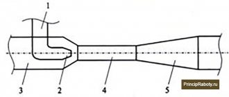
- Overall and connecting dimensions of KM type pumps.
KM pumps, in accordance with generally accepted classifications, include:
– by design – cantilever (unlike K-type pumps
, the impeller is located directly on the shaft of a specially designed drive motor or on an intermediate shaft, which is also mounted on the shaft of a conventional flanged or combined mounting type electric motor). - according to the principle of operation - centrifugal, dynamic, bladed, with an output flow at the exit of the radial type impeller (impeller - closed type).
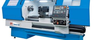
Cantilever monoblock pumps KM
by type of pumped medium, they are designed mainly for water (except sea water) and liquids similar to water in density, viscosity (up to 36 cSt), with a pH value from 6 to 9. KM monoblock pumps for special purposes are also produced:
– for pumping chemically active media (XM pump), – light petroleum products (KMN pump), – food products – other monoblock pumps for various media. Most household pumps are produced in a monoblock design.
Temperature of the pumped liquid for KM water pumps:
– with an stuffing box seal – from 0 to 80 o C, – with a mechanical (end) seal – from 0 to 105 o C (short-term excess of the maximum temperature up to 120 o C is allowed).
– for pumps with gland seal – 3.5 atm. – for pumps with mechanical seal – 6 atm.
KM pumps allow a small amount of mechanical impurities in the pumped liquid: up to 0.2% by weight. Particle size in impurities is up to 0.2 mm. Suction height ( KM pump is not self-priming
) varies depending on the brand of pump. To determine the suction height of the pump (when pumping water from an open source, at normal atmospheric pressure, at a water temperature of 20 o C), you can use a simplified formula
Cantilever monoblock pumps are devices with a centrifugal design; their type is single-stage monoblock; the nature of the supply of the working liquid mass is unidirectional. The scope of application of these pumps is water supply, circulation processes and heating systems. They are used for pumping water and liquids similar to it in physical properties.
This includes clean, drinking water, industrial water for use in production, the pH should be from 6 to 9. The exception is sea water. Pumps can also pump other liquids that are close to water in density, viscosity and chemical activity. Solid inclusions should not exceed 0.2 mm, the concentration per unit volume should be up to 0.1%.
The temperature regime of the working fluid for devices such as cantilever monoblock pumps is from 0 to 850C (with a single gland seal) or up to 1050C (if the mechanical seal is single). Cantilever monoblock pumps are not allowed for use in industries with explosion and fire hazards, as well as for pumping flammable liquids. The following materials are used in the pumps: the flow part is made of gray cast iron, the shaft end seal is a single stuffing box.
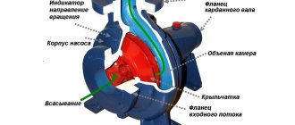
Design of a cantilever monoblock pump
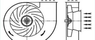
The equipment of such equipment as cantilever monoblock pumps, by analogy with cantilever pumps, has a centrifugal wheel, a pipe for receiving and discharging liquid mass, a spiral-ring outlet, a housing, and clamps. The impeller is made in the form of two disks with curved blades between them. Cantilever monoblock pumps and cantilever pumps have differences in weight and size and, in addition, in the design of connections to the electric motor.
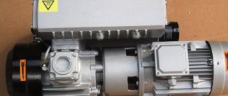
In cantilever monoblock pumps, an extended shaft in the motors is used for drive. The impeller is attached to the end of this shaft. This connection method is more reliable due to the smaller number of bearing units.
The design of mechanisms such as cantilever monoblock pumps consists of a volute casing with axial suction and radial discharge pipes, the angle between them is 900. The impeller is mounted on the electric motor shaft. The pump housing and the electric motor are connected by a drive lantern; an O-ring is located between the lantern and the pump housing. A coupling is attached to the center of the lantern. The design of the pump allows for the removal of the electric motor and impeller without dismantling the pump housing. Both the pump and the electric motor are mounted on the same steel frame.
Operating principle, installation
The principle of operation of a cantilever pump is not complicated and is determined by the main design features. When the electric motor is turned on, the blades on the impeller begin to rotate rapidly. Due to this, strong pressure is built up and the liquid is pumped, being drawn into one hole and squeezed out of another, located on the opposite side of the disk. The speed of pumping water increases significantly when the wheel begins to rotate faster.
However, excessive acceleration can cause cavitation due to reduced inlet pressure levels. More specifically, the cavitation process is caused by vapor formation accompanied by condensation of air contained in the working fluid. For this reason, selecting the appropriate cantilever pump should always be the responsibility of an experienced professional.
To operate a cantilever pump, a reliable base is required in the form of a concrete foundation, which is approximately 20 cm larger in size than the pump housing. The thickness of the base must be at least 20 cm. The frame of the pumping device must be firmly fixed to the base. For this purpose, special anchors are often used. A special gasket is placed between the foundation slab and the device body to absorb vibration. On the nozzles of the pumping device in front of the pipe structures, it is necessary to install shut-off valves, as well as counter flanges, which ensure a sufficiently reliable connection of the nozzles and pipe structures.
Operating principle of a cantilever centrifugal monoblock pump
During the operation of cantilever monoblock pumps, the electric motor transmits torque to the impeller through the shaft. The inlet pipe is filled with liquid, which is forcefully ejected through the outlet pipe with greater pressure and speed compared to the inlet pipe. This process occurs through centrifugal force, which arises from the rotation of the impeller.
When liquid is ejected into the outlet pipe, a vacuum occurs in the center of the wheel, resulting in a pressure difference between the pump inlet and its center. Under the influence of a pressure difference, the product moves from the inlet pipe to the pump housing, where it is again captured by the centrifugal force of the wheel, after which the process of moving the liquid is repeated.
The precision of the technological execution of the design of such equipment as cantilever monoblock pumps allows the use of high-quality technical functioning of the devices over a long period, without the need for replacement or repair.
For cold and hot water - these are units designed for pumping liquid (water); by type of design: horizontal, single-stage, with one-way liquid supply to the impeller located at the end of the pump shaft. In terms of design, technical characteristics, and areas of application, they are centrifugal pumps for water. The main qualities of cantilever monoblock pumps and cantilever pumps are high quality production and long service life, based on the high reliability of these units.
Areas of application
Slurry pumps: technical characteristics, reviews and photos
It is difficult today to find a sector of everyday life or industry that uses liquid media and does not use centrifugal pumps. The most popular areas of application are:
- Water supply of all levels and scales - from water intake stations to industrial enterprises and from residential buildings to wastewater treatment plants.
- Pumping of process fluids in industrial installations and between production facilities.
- Coolant circulation in heating systems, centralized or local.
- Water circulation in washing machines and dishwashers.
- Irrigation of agricultural crops.
- Supplying water to drinkers and pumping milk on productive farms.
- Antifreeze circulation in the cooling system of a car engine and air conditioning systems.
- Filling and draining ballast tanks on surface ships and submarines.
- Transportation of raw materials in the food industry and mass production of beverages.
Circulation pumps are used wherever liquids are used and ultra-high pressure or suction force is not required. For special applications, other types of devices are used - vibration, rotary, piston or induction.
Purpose of cantilever pumps and cantilever monoblock pumps
Cantilever pumps (type K) and cantilever monoblock pumps (type KM) are single-stage centrifugal pumps with a one-way liquid supply to the impeller. They are designed for pumping water (except seawater) and other liquids similar to water in density, viscosity and chemical activity, temperatures from 0°C to 85°C (on special order up to 105°C), containing solid inclusions up to 0. 2 mm, the volume concentration of which does not exceed 0.1%.
Cantilever pump
Symbols of cantilever pumps and cantilever monoblock water pumps
TO
– horizontal cantilever pumps with support on the housing, with rotation transmitted from the engine through an elastic coupling.
KM
,
KMM
– cantilever monoblock (KMM – modernized) pumps. The pump impeller is mounted on the end of an extended electric motor shaft.
Pump symbol according to GOST 22247-96: Consider, for example, the K80-50-200-S-UHL4
.
K
– pump type (cantilever);
80
– nominal diameter of the inlet pipe, mm;
50
– nominal diameter of the outlet pipe, mm;
200
– nominal diameter of the impeller, mm;
C
– symbol of a single pump shaft seal or
SD
– double seal;
UHL
– climatic version;
4
– category of unit placement during operation of
a cantilever monoblock pump
Repair
Overhaul of the pump is carried out after the installed resource of the unit has been exhausted. The optimal duration of the operating period is determined by the model and brand of the pumping unit.
The most common problems during operation are:
- No pressure after startup. Similar problems can arise as a result of clogging or the formation of voids in the impeller, which must be filled with liquid;
- Poor productivity may be due to wear on the impeller or increased resistance in the feed hose;
- Wear of insulating devices or a significant increase in pressure in the system can cause leakage;
- Bearings may overheat due to changes in shaft alignment or insufficient lubrication;
- Increased vibration and high noise during operation may indicate that the cavitation reserve is increased, the pump is not tightly fixed on the concrete platform, or the bearings require replacement.
During operation, cantilever pumps require constant maintenance, as well as preventive repairs approximately every 3 months.
Operating principle and design of cantilever pumps and cantilever monoblock pumps
The main working part of a cantilever water pump is a centrifugal wheel. A centrifugal wheel consists of a pair of disks with blades located between them, connected into a common structure. The impeller blades have a smooth bend in the direction opposite to the direction of rotation of the impeller. This device is the most common. With such a device, the impeller is called closed. Sometimes you can find cantilever centrifugal pumps with an open impeller design, which in this case consists of a single disk. When the impeller rotates, the liquid inside it is subjected to a centrifugal force directly proportional to the distance of a unit of liquid from the center of the impeller and the square of the angular speed of rotation of the impeller. Under the influence of this centrifugal force, water is pushed out of the impeller into the pressure (outlet) pipe of the cantilever centrifugal pump, and a vacuum occurs in the central part of the impeller, and high pressure occurs in its peripheral part. The flow of liquid from the suction pipeline occurs due to the difference in pressure at the surface of the water in the receiving tank and in the central part of the wheel.
Typically, cantilever centrifugal pumps include single-stage centrifugal pumps, cast iron in construction material, with one-way liquid supply, the impellers of which are located at the end of the electric motor shaft. Other types of industrial pumps, such as sewage, chemical, and soil pumps, also have this type of design.
The design of cantilever and cantilever monoblock pumps at the location of the sealing unit depends on the temperature of the pumped liquid, as well as the pressure in the supply pipe at the inlet to the pump. Barrier fluid is not supplied to the single soft seal. In the double gland seal, at a temperature of the pumped liquid up to 90°C, the barrier liquid is supplied to the dead end, and at a temperature above 90°C - to the flow. The pumped liquid from the pressure pipeline can be supplied to the single mechanical seal. In the double mechanical seal of the cantilever pump, the barrier fluid is supplied only to the flow path. In all cases, the barrier fluid is supplied under pressure exceeding the pressure before compaction by 0.5...1.5 kgf/cm2. Any non-toxic and non-explosive liquid with a temperature not exceeding 40°C, containing particles up to 0.2 mm in size with a volume concentration of up to 0.1%, can be used as a barrier liquid. The maximum permissible excess pressure of the pumped liquid at the inlet: for cantilever water pumps with a gland seal - 3.5 kgf/cm2, for cantilever and cantilever monoblock pumps with a mechanical seal - 8 kgf/cm2.
The maximum permissible external water leakage through the gland seal of a cantilever centrifugal pump is up to 3 l/h (liquid must leak through the gland to lubricate and cool the sealing surface). Leakage through the mechanical seal is significantly less and, ideally, can be close to zero.
Rules for installing pump equipment type KM
Centrifugal pumps design and principle of operation
The installation location of the console-type unit must meet the following parameters:
- The KM pump is installed in a place where there is a normal approach for maintenance and installation.
- The parts of the pipeline connected to the inlet and discharge pipes are fixed on separate supports. This is necessary to ensure that the load from the pipeline is not transferred to the pump flanges. It is also necessary to install temperature compensators on the inlet and pressure parts of the pipeline.
- The pipe on the suction side is installed with an inclination towards the intake tank in the most direct and shortest way to create cavitation-free operation of the pump.
- The check valve is installed at the pump outlet.
- To control the liquid pressure, pressure gauges and mono-vacuum gauges are installed at the inlet and outlet of the electric pump.
- If a barrier fluid is needed for the operation of the console mechanism, then it is supplied. Drainage outlets are also required to ensure the removal of fluid leaks from the pump.
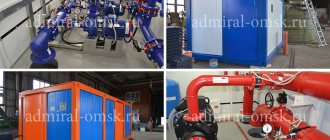
KM pumps in industrial environments
After installing the console device, the entire pipeline is checked for strength and tightness. To do this, create a test pressure corresponding to the system parameters. They also check the operation of the rotor: there are no jams during rotation and contact with moving or stationary parts. Before starting the pump for the first time, all taps must be closed. In this way, their serviceability and the pressure level on the pressure gauges are checked.
Table of technical characteristics of cantilever pumps and cantilever monoblock pumps.
| Pump name | Supply, m3/h. | Napor, m. | Engine, kW* rpm | d in, mm | d out, mm | Weight, kg | Dimensions, mm. LxBxH |
| K8/18 | 8 | 18 | 2,2*3000 | 40 | 32 | 58 | 764*257*323 |
| K50-32-125 | 12,5 | 20 | 2,2*3000 | 50 | 32 | 58 | 764*257*323 |
| K20/30 | 20 | 30 | 4*3000 | 50 | 40 | 78 | 827*299*332 |
| K65-50-125 | 25 | 20 | 3*3000 | 65 | 50 | 120 | 730*368*325 |
| K65-50-160 | 25 | 32 | 5,5*3000 | 65 | 50 | 140 | 925*408*338 |
| K45/30 | 45 | 30 | 7,5*3000 | 50 | 40 | 126 | 1030*332*413 |
| K80-50-200 | 50 | 50 | 15*3000 | 80 | 50 | 255 | 1120*458*455 |
| K80-50-200a | 45 | 40 | 11*3000 | 80 | 50 | 185 | 990*428*425 |
| K100-80-160 | 100 | 32 | 15*3000 | 100 | 80 | 275 | 1105*458*450 |
| K100-80-160a | 90 | 26 | 11*3000 | 100 | 80 | 200 | 1105*458*450 |
| K100-65-200 | 100 | 50 | 30*3000 | 100 | 65 | 370 | 1290*498*510 |
| K100-65-200a | 90 | 40 | 18,5*3000 | 100 | 65 | 325 | 1265*498*475 |
| K100-65-250 | 100 | 80 | 45*3000 | 100 | 65 | 485 | 1440*568*620 |
| K100-65-250a | 90 | 67 | 37*3000 | 100 | 65 | 460 | 1390*568*605 |
| K160/30 | 160 | 30 | 30*1500 | 150 | 100 | 420 | 1515*515*555 |
| K160/30a | 140 | 28,6 | 22*1500 | 150 | 100 | 400 | 1465*515*555 |
| K160/30b | 140 | 22 | 18,5*1450 | 150 | 100 | 340 | 1495*505*530 |
| K150-125-250 | 200 | 20 | 18,5*1500 | 150 | 125 | 410 | 1325*475*455 |
| K150-125-315 | 200 | 32 | 30*1500 | 150 | 125 | 422 | 1375*540*610 |
| K290/30 | 290 | 30 | 37*1500 | 200 | 150 | 550 | 1645*575*630 |
| K290/30a | 250 | 24 | 30*1500 | 200 | 150 | 460 | 1555*515*585 |
| K200-150-250 | 315 | 20 | 30*1500 | 200 | 150 | 422 | 1375*540*610 |
| K200-150-315 | 315 | 32 | 45*1500 | 200 | 150 | 570 | 1665*600*720 |
| KM50-32-125 | 12,5 | 20 | 2,2*3000 | 50 | 32 | 47 | 500*200*202 |
| KM65-50-160 | 25 | 32 | 5,5*3000 | 65 | 50 | 76 | 578*250*272 |
| KM80-50-200 | 50 | 50 | 15*3000 | 80 | 50 | 90 | 790*350*420 |
| KM80-65-160 | 50 | 32 | 7,5*3000 | 80 | 65 | 90 | 630*320*362 |
| KM100-80-160 | 100 | 32 | 15*3000 | 100 | 80 | 195 | 790*350*420 |
| KM100-65-200 | 100 | 50 | 30*3000 | 100 | 65 | 260 | 865*400*440 |
| KM150-125-250 | 200 | 20 | 18,5*3000 | 150 | 125 | 195 | 870*370*705 |
Our Company offers a full range of industrial and domestic pumps, including cantilever pumps, drainage, self-priming, fecal, irrigation, well and many, many others. You can familiarize yourself with the range and technical characteristics on the website page.
Cantilever monoblock pumps are horizontal single-stage cantilever pumps with a one-way liquid supply to the impeller. These pumps, like conventional cantilever pumps, are designed for pumping clean water (except sea water) under stationary conditions, with pH = 7, temperature from 0 to 85 ° C, containing solid inclusions up to 0.2 mm in size, the volume concentration of which does not exceed 0.1%, as well as other liquids similar to water in density, viscosity and chemical activity. The scope of application is identical to the scope of application of cantilever pumps of type K. The advantage of cantilever monoblock pumps is their compactness compared to cantilever pumps of type K. This advantage makes it possible to install pumps in a limited area. However, there is also a drawback that after turning the impeller it is impossible to select a three-phase electric motor with a lower power. The reason lies in the design of the pump and the monoblock electric motor with an extended shaft specially designed for the pump. The cast-iron pump casing conceals its main working element – the centrifugal impeller (cast iron grade SCh20 or SCh25). The role of the pump shaft is actually played by the shaft of a three-phase electric motor, since the pump impeller is mounted on the electric motor shaft. There are two main types of shaft seals: single gland seal and single mechanical seal. The stuffing box seals are designated by the letter “C” to the main brand; if it is not there, then it is implied. Leakage through the gland seal is no more than 2 l/h, to lubricate and cool the soft packing. Single mechanical seal – brand index “5”. External leakage through the mechanical seal is no more than 0.03 l/h. Pumps with mechanical seals can pump liquids with temperatures from 0 to 115 ° C. Pressure at the pump inlet is up to 8.0 kgf/cm2.
An example of a pump unit symbol:
KM80-50-200 a-5 UHL4
- KM
– pump type – monoblock console pump, centrifugal - 80
– diameter of the suction inlet pipe, mm, - 50
– diameter of the pressure outlet pipe, mm, - 200
– nominal diameter of the impeller, mm, - a
– first turning of the impeller, - 5
– designation of a single mechanical seal, - UHL4
– climatic version and placement category.