Pumping equipment servicing pipeline systems through which liquid media are transported especially needs protection at the moment when the liquid pressure drops or it stops flowing altogether. To provide such protection in situations where the pump is not supplied with the liquid it pumps, it is equipped with automatic sensors - dry-running relays. Various types of such devices can be used for a pumping station.
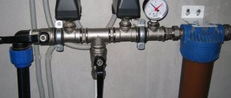
Well pump control system: dry running relay on the left, pump on/off sensor on the right
Why pumping equipment must be protected from dry running
Whatever source the electric pump pumps water from, this equipment may find itself in a situation where liquid stops flowing into it. It is precisely such situations that lead to the fact that the pumping station begins to operate at idle (or, as they more often say, on dry) running. The negative consequence of operating the pump in this mode is not even a waste of electricity, but intense heating of the equipment, which ultimately leads to deformation of its structural elements and rapid failure. Water simultaneously acts as a lubricant and coolant, so its presence inside the pump is simply necessary.
For this reason, the presence of a relay that provides protection against dry running of a well pump (or circulation pump) is almost mandatory. Most modern models of pumping equipment have built-in relays. However, such pumps are very expensive. For this reason, users often purchase dry-running protection relays separately.
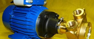
Pumping station with automatic dry-running protection
Configuring the connected protective relay
The device is designed in such a way that the relay regulates the level of communication between the triggered contact group and the surface that responds to pressure force. This function is performed by special screws - they loosen and tighten the spring. The manufacturer sets the lower and upper thresholds. Most often these are indicators:
- 1.4 atmospheres - minimum;
- 2.8 - maximum.
The user can independently adjust the boundaries - the screw is turned left or right.
Note! A mandatory requirement for correct protection settings is to fix the device shutdown threshold below the pump pressure. If this rule is ignored, the pump will not respond - the equipment will quickly break down.
The second adjustment screw is designed to determine the difference in the sensitivity limits of the device. During the setup process, keep in mind that the upper shutdown threshold also changes. Your task is to prevent exceeding the maximum pressure that the equipment produces directly.
Reduce the lower level and the spread of the boundaries by unscrewing the nuts.
Basic protection
To protect the pump from dry or idle running, various types of devices are used, the main task of which is to stop the operation of the equipment the moment water stops flowing into it. These include, in particular:
- dry running pump protection relay;
- water flow sensor;
- pressure switch with dry run protection option;
- sensors that monitor the liquid level in a water supply source, which can be float switches or level control relays.
The differences between all of the above devices lie both in their design and operating principle, as well as in the areas of their application. To understand in what situations the use of one or another type of relay that protects pumping equipment from dry running is most appropriate, you should get to know each of them in more detail.
Three camera models
Three-chamber devices allow you to very accurately regulate the pressure inside the system. Most modifications are launched from the module. To connect the device, adapters with a ring are used. Models are suitable for pumps with power from 4 kW. Their operating frequency is at least 4 Hz. Some relays are made on actuators. Caps are typically installed over the pin. Some devices are manufactured with two clamping plates. The output cable extends from the contactor. A relay of this type operates as a standard from a 220 V network.
Characteristics of the pump dry running protection relay
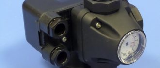
A dry running sensor for a pump is an electromechanical type device that monitors whether there is pressure in the system through which water is transported. If the pressure level is below the standard threshold, such a relay automatically stops the operation of the pumping equipment, opening its electrical supply circuit.
The dry-running relay for the pump consists of:
- a membrane, which is one of the walls of the inner chamber of the sensor;
- a contact group that provides closing and opening of the circuit through which electric current flows to the pump motor;
- springs (the degree of its compression regulates the pressure at which the relay will operate).
Main elements of the dry-running relay
The principle by which such a dry-running protection relay works is as follows.
- Under the pressure of the water flow in the system, if its level corresponds to the standard value, the membrane of the device bends, acts on the contacts and closes them. In this case, the electric current is supplied to the pump motor, and the latter operates normally.
- If the water pressure is insufficient or does not enter the system at all, the membrane returns to its original state, opening the electrical power supply circuit of the pumping unit and, accordingly, turning it off.
Situations when the liquid pressure in water supply systems decreases sharply (which means the pump requires protection from dry running) are caused by various reasons. Such reasons include depletion of the natural water source, clogged filters, too high location of the self-priming part of the system, etc.
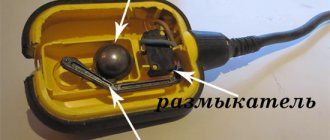
A pump dry running protection relay is usually installed on the surface of the earth, in a dry place, although there are models made in a moisture-proof housing that can be mounted together with pumping equipment in a well.
An example of automatic water supply for a residential building
Relays that prevent the pump from running dry work more effectively when they are installed in systems that are not equipped with a hydraulic accumulator and are served by a surface circulation pump. It is, of course, possible to install such a relay in a system with a hydraulic accumulator, but in this case it will not be able to provide one hundred percent protection of the pumping unit from dry running. The relay connection diagram is as follows: it is placed in front of the water pressure sensor and the hydraulic accumulator, and immediately after the pumping station a check valve is installed that prevents water from moving in the opposite direction. With this connection, the dry-running relay membrane is constantly under water pressure created by the hydraulic accumulator. This can lead to the fact that the pump, which will not receive water from the source, simply will not turn off.
Effective protection of the pump from dry running in cases where it serves systems in which a hydraulic accumulator is installed is also possible, but other types of devices are used to solve this problem.
Dual chamber devices
Double-chamber devices are manufactured with low conductivity contactors. Most models are equipped with multiple pins. The nuts are usually located at the top of the housing. The outlet pipe is used with a diameter of 4.4 cm. The devices are suitable for high power pumps. Modifications operate from a 220 V network. If we consider models with drive contacts, then they use a trigger mechanism from the module. The minimum operating frequency is 30 Hz. The frame is quite often made of steel. The pressure increases by adjusting the screw. The clamping plate in the devices is located under the contactor. The relay base has a seal. Most devices are equipped with a cap to lubricate the pin.
Sensors that control water flow
In situations where an undesirable phenomenon such as dry running occurs, the fluid flow that enters the pump either has insufficient pressure or is absent altogether. In order to monitor the presence of flow and its operating parameters, special devices are used, which are called water flow sensors. According to their design and operating principle, they can be electromechanical (sensors) or electronic (controllers).
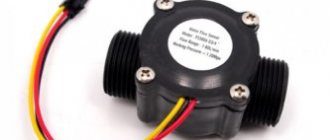
Water flow relays or sensors
There are two types of electromechanical water flow sensors:
- petal;
- turbine
The main working element of the first type of sensors is a flexible plate installed in their internal cavity, which has a cylindrical cross section. If there is a fluid flow in the system and has sufficient pressure, such a plate, equipped with a magnetic element, is as close as possible to the reed switch type, and its contacts are in a closed state. If the pressure of the fluid flow decreases or it disappears altogether, the flexible plate moves away from the switch, its contacts open, which leads to the pumping unit being turned off.
Leaf type flow sensor device
Turbine-type flow sensors have a more complex design. Its basis is a small turbine, in the rotor part of which an electromagnet is installed. The operating principle of such a sensor, which is also capable of protecting the pump from idling, is as follows. The fluid flow rotates a turbine, in the rotor of which an electromagnetic field is created, which is then converted into electromagnetic pulses read by a special sensor. The sensor makes the decision whether to turn on or off the pumping equipment servicing the system depending on how many pulses the turbine sends to it per unit time.
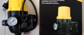
Automatic pump control sensor "Turbi"
Electronic water flow controllers
Electronic water flow controllers, which combine the functions of both a pressure switch and a device that protects pumping equipment from dry running, have an even more complex design. Such controllers, also called electronic pressure switches, although not cheap, replace several monitoring and control devices at once. Installed in water supply systems, electronic pressure switches not only protect the pumping system from dry running, but also allow you to control the pressure and fluid flow parameters. When such system operating parameters do not correspond to standard values, an electronic sensor automatically turns off the pumping equipment.
Electronic pressure controller EPS-II-12, combining the functions of a pressure switch and a flow switch
If a pump with a small head reserve is used to service water supply systems, then they can only be equipped with an electronic relay. When the system uses a pump with a large margin of the pressure it creates, a hydraulic accumulator and a separate pressure sensor are needed, since the electronic relay is not regulated by the maximum shutdown pressure of the pumping unit. Using only an electronic relay in such cases can lead to the fact that when excess pressure is created in the system, the pumping station simply does not turn off.
Checking the pressure in the accumulator
When setting up the pump relay, first determine the air pressure in the empty accumulator tank, which should be equal to 1.5 atm. However, during transportation or long-term storage of the pump, a small air leak occurs in the hydraulic tank, which subsequently reduces the water pressure in the tank.
When measuring pressure in a pumping apparatus, use a car or electronic pressure gauge.
In order to determine the pressure of the hydraulic accumulator in the pumping apparatus, you need to unscrew the cap under which the nipple is installed, attach a pressure gauge to it and record the obtained value. If this parameter turns out to be small, then a large amount of water can be poured into it.
To ensure powerful water pressure, the air pressure must be at least 1 atm. In such a situation, it is possible to provide for the domestic needs of small houses.
With high water pressure, the pump device turns on more often, as a result of which the service life of the pump decreases. At the same time, the water pressure in the water supply at the dacha remains the same as in the city. In such a situation, you can take a hydromassage bath.
With low water pressure, wear on the pumping apparatus becomes less, however, in this case, the owner of the apartment can only take a regular bath with hot water, and not a Jacuzzi.
How to choose a device?
When purchasing equipment, pay attention to the design, material of manufacture, and technical parameters. The controller is selected according to the following characteristics:
- power;
- pressure;
- IP protection class;
- inlet/outlet diameter;
- product manufacturer;
- presence of an expansion tank;
- restart function;
- price.
The IP class in the electronic regulator indicates protection against dust and moisture.
Example of decoding IP 65 on the device:
- IP - Ingress Protection;
- 6 - from dust;
- 5 - from moisture.
IP 65 - high protection class.
The pressure regulator is selected depending on the functionality of the pump.
The following parameters of the hydraulic machine are taken into account:
- operating principle;
- power consumption;
- performance;
- water pressure.
When choosing automation, the plumbing equipment in the house is taken into account. Household appliances are designed for pressure up to 3 atm. If the pressure is greater, the equipment is subject to stress and fails.
Reference! Pumping stations are sold complete with pressure regulators. There is a wide range of automatic water switches on sale.
