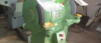
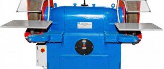
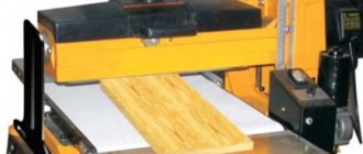
Design and operating principle of the 3L631 sharpening machine:
Supplied as a tabletop, mounted on a workbench. Two 200mm abrasive wheels are installed on the shaft; each has a protective screen above it. In front of the circles, hand tools are attached, on which the workpiece is placed for processing. On the front part of the emery board there are 3L631 buttons to turn the engine power on and off. An industrial vacuum cleaner or a workshop hood can be connected through the pipes at the back; when processing metal, all chips and dust are filtered. If necessary, the 3L631 sharpening machine can be equipped with wheels of smaller diameter and diamond wheels for high-precision tool sharpening. The average service life is 10 years.
Information about the manufacturer of the universal sharpening machine 3K631
The grinding and grinding machine model 3K631 was produced by the Mukachevo Machine Tool Plant named after. Kirov is currently Mukachevo Machine Tool Plant, OJSC .
Machine tools produced by the Mukachevo Machine Tool Plant named after. Kirov
- 3B632, 3B632v
- sharpening and grinding machine for sharpening cutters 50 x 50 - 3B634
– floor-mounted grinding and grinding machine Ø 400 - 3D641e
- universal sharpening machine Ø 250 x 650 - 3K631
— tabletop grinding and grinding machine Ø 150 - 3K634
– floor-mounted grinding and grinding machine Ø 400 - 3L631
– tabletop grinding and grinding machine Ø 200
Technical characteristics of the grinding and grinding machine 3L631:
| External Ø of circles, mm | up to 200 |
| Drive power, kW | 0,75 (*2,2) |
| Spindle speed, rpm | 2840 |
| Accuracy class | P |
| Height from base to spindle axis, mm | 160 |
| Distance between circles, mm | 385 |
| Speed of circles, m/sec | 30 |
| Mains voltage, V | 380 |
| Dimensions 3L631, m. | 0,6*0,4*0,4 |
| Weight 3L631, kg. | 43 |
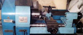
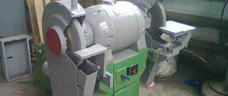
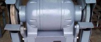
3K631 Double-sided tabletop sharpening and grinding machine. Purpose, scope
3k631 double-sided benchtop grinding and grinding machine was replaced by a more advanced model 3L631
.
The grinding and grinding machine model 3K631 is made in a desktop version and is intended for use in tool and repair shops of various metalworking enterprises, in repair shops in agriculture, construction, transport, including in mobile repair shops, educational institutions, etc.
The sharpening and grinding machine with two wheels, model 3K631, is designed to perform the following operations:
- sharpening of metal-cutting, woodworking and other high-speed tools equipped with hard alloy plates;
- sharpening drills with a diameter of 5..25 mm;
- sharpening of metalwork tools;
- removal of burrs, chamfers and other metalwork works;
It is not recommended to use the machine for stripping cast and welded parts.
Design features and operating principle of the machine
3K631 machine was produced in two versions:
- Standard version - 3K631
- Special version for mobile workshops - 3K631-01 (upon customer request).
With the help of special devices, supplied for an additional fee, high-quality sharpening of drills is carried out.
Machine accuracy class 3K631 - N.
Machine adjustment
The machine is produced by the factory adjusted and does not require adjustment until individual structural elements wear out, therefore, adjust the machine mechanisms only after its necessity has been established.
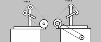
If the grinding spindle has axial play, or the surface of the machined part is not clean enough, adjust the bearing units of the machine, creating the appropriate preload of the bearings (Fig. 15).
Scheme of duplexing of bearings of the 3K631 machine
Preload is carried out by adjusting the wear rings. The spacer inner ring is finally ground to size;
H = (H1 - ΔI) - 0.01
where: H1 is the actual thickness of the outer spacer ring, measured with an accuracy of 0.01 mm;
ΔI = (a - b) arithmetic mean of three measurements taken at an angle of 120° between the ends of the inner rings of bearings;
a is the distance between the inner rings of bearings in mm;
b—thickness of the measuring insert in mm.
Periodically check and adjust the smooth rotation of the dressing tool installed in the holder of the grinding wheel dressing device.
The dressing tool should rotate (by hand) smoothly, without jerking or noticeable axial motion.
Backlash is eliminated by adjusting the gaps in the roller supports.
Installation drawing of grinding and grinding machine 3K631
Electrical equipment
General information
The machine is equipped with a built-in asynchronous electric motor of the 4A series. The electric motor is controlled and protected by an automatic switch located on the front wall of the stand.
On the back wall of the stand in the version of the 3K631-01 machine (for field workshops), a packet-cam switch of the PKU-3 type is additionally installed, which is used to set the value of the three-phase supply voltage (220 or 380 V). The supply wires are entered through a flange elbow located on the back wall of the stand. There is also a grounding screw there.
Description of work
Before starting work during the initial start-up, first of all, check the reliability of grounding and the quality of installation of electrical equipment by external inspection. Starting and stopping the drive electric motor (M) and protection against short circuits is carried out by an automatic switch (B1).
ATTENTION! In the machine version 3K631-01, pay attention to the correct position of the switch (B2) in accordance with the mains voltage.
When installing, the machine must be reliably grounded and connected to the grounding system.
Design, operation of the machine and its components
Stand
The stand (Fig. 1, item 1) serves as the base of the machine; a grinding head is mounted on its upper plane, the internal cavity of which communicates through windows with the internal cavity of the stand for air circulation that cools the electric motor windings. Handles and devices for sharpening drills are attached to the head covers.
The legs of the stand have holes for mounting the machine on a workbench or cabinet
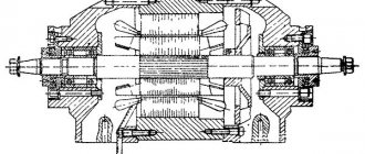
Grinding head
Grinding head of grinding and grinding machine 3K631
The grinding head housing (Fig. 3) consists of 3 parts. The central cylindrical part, the head housing 2, houses a built-in electric motor, and the side parts 1 and 4 (covers) contain spindle supports in the form of duplex angular contact ball bearings of high precision. The cavities of the bearing units are filled with refractory grease during assembly and protected by labyrinth seals.
Cooling of the electric motor windings is ensured by air circulation in the head housing and stand, carried out using the fan impeller 3.
The grinding head covers are castings, on the end surfaces of which the casings of the grinding wheels are attached, and on the front surfaces - the tool rests.
Podruchnik
The tool rest (Fig. 4) is designed for installing parts when performing sharpening work. It consists of a table, bracket and fasteners.
The table is a steel part that has two working surfaces: flat and curved. A flat working surface is used when grinding parts that have a reference plane, a curved one is used when grinding parts when there is no good reference plane or when it is necessary to frequently readjust the angle of the tool rest.
The table has a groove for installing a device for straightening abrasive wheels.
The table is attached to the bracket and can rotate around its axis and move horizontally as the grinding wheel wears to maintain a minimum gap between the wheel and the table.
Housings
Covers are attached to the end surfaces of the grinding head (Fig. 5), designed to protect against rupture of grinding wheels, collection and removal of abrasive dust.
Welded casings have additional walls 3 and dampers 5, which allow the abrasive dust, entrained by the grinding wheels during their rotation, to be directed to the outlet pipes 2, which are used for connection to the workshop ventilation system, connection of a dust suction unit or dust collectors.
The flaps are moved manually as the grinding wheels wear.
In the operating position, the dampers are held by screw clamps 4. Large abrasive particles fall through the grate in the lower part of the casing into tray 1.
To install grinding wheels, the casing has a cover mounted on hinges with a vertical axis of rotation and secured with captive screws.
Attachment of grinding wheels
The fastening of grinding wheels (Fig. 6) at the ends of the spindle is carried out on adapter flanges 1 through cardboard spacers 2 using nuts 3 with left and right threads, for the left wheel - left thread, for the right wheel - right.
Screen
Screen clips 1 (Fig. 7) are fixed in the upper part of the casings. The protective part of the 2 screens is made of safety glass and connected to the frames with screws.
Device for dressing abrasive wheels
Dressing of grinding wheels (Fig.) is carried out with a carbide disk 1 installed in a small-sized holder ATR-1. The movement of the housing 2 with the holder along the generatrix of the grinding wheel is carried out along the groove of the tool rest, into which the guide pin of the housing fits.
Accessories
The set of accessories includes a grinding wheel remover and a set of assembly tools.
Device for sharpening drills 3K631.45A.000
The device (Fig. 9) is installed on the left side of the machine and attached to the head cover instead of a tool rest. Range of sharpened drills Ø 5..25 mm.
Sharpening of drills is carried out by the periphery of the grinding wheel along the helical surface. The device provides an angle at the tip of the drill within 70°... 140° and a back angle of up to 20°.
The main parts of the device are a prism 6, a copier 7 and a set of clamps 5.
The rear sharpening angle is set by rotating the prism to the required angle on a scale of 12 and fixed with screw 4.
The angle at the tip of the drill is set according to scale 3 and fixed with screw 1. The same screw fixes prism 6 in the required position on axis 2, which is selected depending on the diameter of the drills being sharpened according to the table;
The drill is installed in the clamp and prism.
The clamp 5, corresponding to the diameter of the drill, is secured to the drill with a screw 15 so that its end falls into the groove of the drill. Drills with a diameter of up to 9.5 mm are secured in the clamp with a screw with a conical shank; the clamping occurs along the outer diameter of the drill. Rocking of the drill in the clamp is not allowed.
The stop of the clamp should be on the edge of the copier. In this position, ensure that the cutting edge of the drill blade is located parallel to the generatrix of the grinding wheel by turning the stop 14.
After setting the stop, it should be secured with screw 13.
When the drill contacts the grinding wheel at the beginning of sharpening, the stop of the clamp should be spaced from the copier by the amount of allowance “P” to be removed, which is selected depending on the degree of dullness of the drill.
By turning the clamp with the drill fixed in it left and right and pressing the drill against the grinding wheel, they sharpen one blade of the drill until metal removal stops due to the fact that the stop 14 of the clamp rests on the carbon bevel.
After this, without loosening the drill in the clamp, turn it 180° and sharpen the other drill blade in a similar way.
Device for sharpening drills 3K631.46A.000
The device (Fig. 10) is used for sharpening drills Ø 2..6 mm. The principle of its operation is similar to that described above.
The device consists of a prism, a clamp and a copier. The remaining parts are used from fixture 3K631.45A.000.
The drill is clamped in the clamp using a screw with a conical end along the outer surface of the drill.
The prism for drills Ø 2..4 mm is installed on the axis pos. 2 (see Fig. 9) to position 1, and for drills Ø 5 and Ø 6 - to position 2.
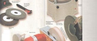
Dust extraction unit kit
The main part of the kit (Fig. 11) is a dust extraction unit 1 (PA2-12), connected to the nozzles of the protective casings using flexible rubber hoses 2 through a tee with a damper to direct the flow of sucked air.
Setting up and setting up the machine
To ensure normal operation of all components and increase the service life of the machine, follow the following setup procedure:
- Dress grinding wheels as needed and always when installing new wheels;
- As the grinding wheels wear out, move the tool rest towards the wheel. In doing so, follow the safety instructions;
- For better dust collection, move the flap of the protective casing to the wheel at a minimum distance as it wears out, but the grinding wheel should not touch the flap.
- Before starting work, make sure that the casing pan is not overfilled with sludge. Clean it if necessary.
- If a device for sharpening drills is installed on the machine, use the scales to set the required angle at the tip of the drill.