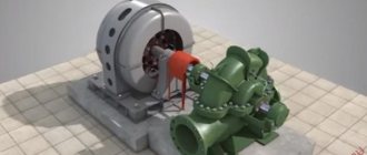
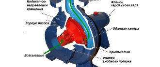
The operating principle of a centrifugal pump is as follows. The liquid medium enters the spiral-shaped pump casing through the inlet with the impeller rotating in it. During the rotation of the impeller, the liquid medium located between its blades, thanks to centrifugal force, enters the outlet and is then discharged from the pump through the pressure pipe. The escaping liquid frees up the space it occupies, so a vacuum is formed at the entrance to the impeller, and excess pressure is formed at the periphery. Under the influence of the difference in atmospheric pressure in the receiving tank and the reduced pressure at the inlet to the pump, liquid is constantly sucked into the inter-blade channels of the impeller.
All centrifugal pumps have a central supply of the pumped liquid to the wheel.
Energy is imparted to the liquid passing through the pump and its pressure at the exit from the wheel and pump is sufficient to overcome the pressure in the pressure line, as a result of which the liquid is supplied by the pump to consumers.
The flow of the pumped liquid in the pump is a continuous jet, and therefore the uniformity of supply of centrifugal pumps is exceptionally high. The higher the speed of rotation of the impeller, the greater the performance of the pump due to an increase in the speed of fluid flow in it.
The design of centrifugal pumps is varied, so a number of criteria are adopted for their classification.
According to suction capacity they are distinguished:
- non-self-priming
- self-priming pumps
A non-self-priming pump is one that does not have dry suction capability, i.e., is not capable of removing air from the suction pipe and housing and creating the necessary vacuum for water to flow. A self-priming pump is one that has dry suction capability.
Pumps themselves with only centrifugal wheels do not have dry suction. Therefore, additional devices are mounted on the same shaft with the centrifugal wheel or driven from this shaft to create the necessary vacuum in the pump during startup. These devices include liquid ring pumps and ejector devices. When combined with a vacuum device, the centrifugal pump is self-priming. Such pumps are installed both above and below the level of the pumped liquid.
Non-self-priming pumps are installed below the level of the pumped liquid, i.e. they operate with support. Sometimes they can be installed above the level of the pumped liquid, but in this case it is necessary to fill the pump with water before starting, or the pump is connected by its suction pipe or housing to a separate independent vacuum device.
Based on the method of supplying liquid to the impeller, pumps with one-way and two-way supply are distinguished. In Fig. Figure 21 shows diagrams of centrifugal pump wheels. The use of a two-way water supply relieves the pump from axial force (see Fig. 21.6).
According to the method of connecting the impellers, pumps are distinguished between multistage and multi-wheeled (Fig. 22) or with a series and parallel connection of wheels. The stepwise activation of wheels in one unit makes it possible to avoid the use of several independent single-wheel pumps. Sequential activation is used to increase pump pressure at constant output, parallel activation is used to increase productivity at constant pressure.
Two-wheel pumps are also manufactured for series and parallel operation. For this purpose, the pump nozzles are equipped with special switching plugs.
Based on the shape of the working blades, impellers with radial, backward-curved and forward-curved blades are distinguished in relation to the direction of rotation of the wheel (Fig. 23). Wheels with blades curved backwards are predominantly used.
Based on the design of the guide vane, pumps with a bladed and bladeless apparatus are distinguished. The bladed apparatus is usually used in multi-stage pumps, and the bladeless (spiral and volute chamber) is used most often in single-stage pumps.
The purpose of the guide vane is to collect the fluid leaving the impeller and reduce its speed to convert dynamic pressure into static pressure.
The classification of pumps can be continued according to other criteria: performance, pressure, type of drive, etc.
Advantages of centrifugal pumps:
- continuous, without pulsation, liquid supply;
- high flow - for example, NTSV 400/30 (RTM - S. Prometheus, sea water pump);
- relatively small weight and dimensions;
- possibility of direct connection with high-speed motors;
- simplicity of design, simplifying the operation and repair of the pump;
- low sensitivity to liquid contamination;
Flaws:
- impossibility of dry suction;
- greater sensitivity to air entering the suction pipeline - air leaks;
- relatively low efficiency compared to piston pumps;
- relationship between pressure and flow;
In recent years, on fishing vessels, on an increasingly large scale, centrifugal pumps have begun to be used to unload fish from nets, catch fish, and also supply fish to technological units.
The peculiarity of the operation of such fish pumps is that they pump a heterogeneous mass: a mixture of fish and water (pulp). They are usually installed on the deck.
Centrifugal fish pumps must meet the following requirements:
- the fish should not get stuck between the wheel blades, which is why the inter-blade channels are made wide enough and the wheels have a minimum number of blades;
- the surfaces of the wheel blades must be smooth and have smooth outlines so that the fish are not damaged;
- on the path of pulp movement in the pump, turns should be made smoothly, and their number should be minimal;
- The pump interior and impeller must be easily accessible for inspection and cleaning.
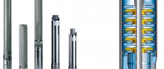
In addition to deck-type fish pumps, modern fishing vessels use submersible centrifugal fish pumps. Such a fish pump is connected to the vessel using a cable, an electric cable, through which power is supplied to the hydraulic drive motor. The fish pump is lowered overboard into the fishing gear or into the hold, lifted and maneuvered using a cargo cable, boom and winch.
Carts
The inlet is a part of the centrifugal pump housing, which serves to reduce losses when the pumped liquid enters the impeller and improve the cavitation qualities of the pump, allows you to create a uniform and axisymmetric velocity field, and make the fluid movement in front of the impeller steady. The connections are either axial or lateral.
Axial connections are most common in cantilever and vertical single entry pumps. In this case, the greatest preference is given to the supply in the form of a confuser pipe as the simplest in design (Fig. 26, a).
Side connections are used in double-entry pumps, as well as in most multistage pumps. Lateral inlets can be of several types: spiral inlets (Fig. 26, b), which make it possible to obtain a certain speed torque at the entrance to the pump impeller; ring leads (Fig. 26, c), which do not create a torque, and leads in the form of tapering elbows (Fig. 26, d).
The spiral supply stabilizes the flow, improves the conditions for its entry onto the impeller blades, and makes it possible to reduce the relative speed of the pumped liquid medium, and, consequently, the losses in the impeller channels associated with diffusivity. The annular supply does not ensure the creation of a uniform velocity field on both sides of the pump shaft and significantly reduces the efficiency of the pump, but such a supply is simple in design. The supply in the form of tapering elbows provides good hydraulic conditions for the pumped liquid to enter the pump impeller, but the overall dimensions of pumps with this type of supply are larger than those with an annular supply.
Shaft connection type
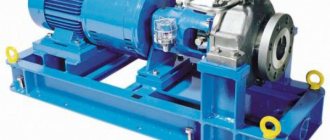
There are 2 ways to transfer rotation from the motor to the pump: through a coupling or directly .
If the pump and motor are two separate machines, then they must be connected by a coupling.
Coupling connection
Couplings come in different shapes, sizes and designs. And one common requirement for them is to ensure the correct integrity of the shafts, otherwise without them, ensuring integrity would be a very sophisticated process.
To facilitate and maintain integrity, the engine and pump are mounted on a common support - a base plate.
Or, in the case of vertical installations, the engine is located on the frame.
This type of connection between the motor and the pump is called coupling. For large powerful installations and pumps with a dismountable casing, connection via a coupling is the only possible option.
The second connection method is direct. The engine and pump are located on a common shaft with a wheel located in a cantilever on the other side of the engine shaft. In this case, the installation does not require a coupling or complex procedures to maintain integrity.
However, because the motor and pump are located on the same shaft, supported only by the motor bearings, this method is only suitable for small and medium-sized end suction pumps.
Impellers
The impeller is designed to convert the mechanical energy received by the pump from the drive into hydraulic energy and transfer it to the pumped liquid medium (water, wastewater, sludge, etc.). Radial impellers are made for centrifugal pumps. There are several designs of impellers. Let's look at the main ones.
The most common impeller is the one-way closed impeller, which consists of a front (outer) disk and a rear (inner) disk, which goes to the center of the impeller into a hub, which attaches the impeller to the pump shaft (Fig. 27, a). Between the disks there are blades that have either a cylindrical or spatial shape. Impellers of water pumps usually have 6–8 blades, while impellers of sewage pumps have 1–4 blades.
A double entry impeller (see Fig. 25) has a higher flow rate than a single entry impeller of the same diameter.
An open-type impeller is sometimes used in small pumps; it does not have a front disk and mates with the front cover of the pump with a small gap (Fig. 27, b). Pumps with such an impeller have reduced efficiency due to increased hydraulic pressure losses.
In most cases, impellers are made by casting, pouring metal into a mold, and only in special cases, for large pumps, are the impeller disks and blades made separately by casting or other means and then joined by welding.
For the manufacture of impellers, cast iron is mainly used, which provides sufficient strength, simplifies the production technology and reduces their cost. However, when rotating in the impellers of large pumps, high stresses arise from the action of centrifugal force, which can destroy the metal. Therefore, for such pumps, impellers are made of ordinary carbon steel, the strength of which is much higher than cast iron.
For special pumps pumping liquid media containing abrasive materials, impellers are made of manganese and other alloy steel with increased hardness. In some cases, for special pumps, the surface of the flow part of the impeller is lined, that is, lined with various materials (elastic, anti-corrosion, etc.). To supply a liquid medium with increased corrosive properties, pumps with bronze impellers are used. Acid pumps use impellers made of special alloys (iron-silicon, iron-chromium, titanium). In recent years, various plastics and polymer materials have been widely used for the manufacture of impellers.
Main manufacturers
The major players in the centrifugal pump market can also be broken down by the industries in which they are strongest:
Water supply, drainage, water treatment
- Grundfos: grundfos.com
- Wilo:wilo.ru
- Xylem Group of Companies. Pumps Lowara, Goulds, Flygt, Vogel, etc.: https://xylem.ru
- KSB: https://www.ksb.com/ksb-ru/
- Pentair: www.pentair.com
- Ebara: https://www.ebaraeurope.ru/
- Caprari: www.caprari.it
Petrochemical industry
- Flowserve www.flowserve.com
- ITT www.itt.com/
- Sulzer www.sulzer.com
- Hermetic Pumpen www.hermetic-pumpen.com
- Kirloskar pumps www.kirloskarpumps.com/
- Ruhrpumpen www.ruhrpumpen.com
Chemical industry
- Munsch munsch.de/
- Pompe Travaini www.pompetravaini.it/
- Someflu pump www.someflu.com/
- Rutschi Gruppe www.grupperutschi.com
Mining industry
- Warman. Weir Mineral Group https://www.global.weir/brands/
- Krebs. flsSmidt Group https://www.flsmidth.com/en-US/Krebs
- Habermann pumpen www.aurumpumpen.de/ru/
Bends
Outlet is a part of the pump casing, which generally serves to collect the liquid medium leaving the channels of the pump impeller, convert the kinetic energy of the liquid into potential energy and supply the liquid to the next stage in a multistage pump or discharge it into the pressure pipeline. Bends are available in annular, spiral, and blade types, as well as composite ones.
The annular outlet consists of an annular channel with a constant or slightly increasing cross-sectional area (Fig. 28, a). Ring bends are used primarily in pumps pumping liquid with suspensions.
The spiral outlet is a channel with ever-increasing cross-sections and ending with a diffuser (Fig. 28, b). Such bends are most often used in single-stage pumps, but the possibility of their use in multi-stage pumps cannot be ruled out.
One of the main disadvantages of spiral bends is that in bends of this type, under off-design operating conditions, radial forces arise, leading to an increase in the deflection of the pump shaft in off-design mode. Thus, when the supply decreases, the spiral outlet acts as a diffuser, and when the supply increases, it acts as a confuser. In both cases, this leads to the fact that the velocity and pressure fields along the outlet section of the impeller cease to be axisymmetric.
To reduce the radial force, spiral bends are manufactured with a baffle. This type of bend is called a double spiral bend (Fig. 29).
A vane outlet (an outlet in the form of a guide vane) can be considered as a stationary circular grid located around the pump impeller and consisting of a series of channels formed by stationary blades. The vane outlet consists of two sections: an initial section with spiral channels and a final section with either diffuser channels (in a single-stage pump) or transfer channels (in a multi-stage pump).
Vane bends are used mainly in multistage pumps.
Large pumps sometimes use compound taps, consisting of a combination of a vane tap with either a volute tap or an annular tap.
The drainage has a significant impact on the efficiency of the pump. The more hydraulically perfect its channels are, the larger part of the dynamic pressure it converts into pressure. In this sense, spiral bends have an advantage over bladed bends; their channels compare favorably with the channels of bladed bends.
Frame
It is made in the shape of a spiral with a decreasing radius, similar to a snail shell. The cavity of this body does not remain the same throughout. The flow area increases as you approach the pressure pipe.
Where the volute casing ends and the discharge pipe begins there is a protruding wedge called a cutwater .
It physically separates the volute housing from the discharge port and ensures that fluid leaves the pump rather than simply spinning around in the volute housing.
The flared part of the volute casing is very important, because with the help of it the pump creates pressure.
Seals
To prevent leakage of the pumped liquid medium from the pump unit, a seal is placed in the place where the shaft passes through the pump body.
All existing seals are divided into two groups. The first group is contact seals. They provide the required effect due to contact with the sealing surfaces of the elastic sealing element: rings, cuffs, gaskets, diaphragms, etc. The second group is non-contact seals. Here, a small gap is specially created between the sealing surfaces, through which a small leakage of the pumped liquid medium is inevitable. The sealing effect, which limits the amount of leakage, in non-contact seals is achieved due to the occurrence of hydraulic resistance when the liquid flows through a small gap.
Basically, in centrifugal pumps, contact seals are used - gland, lip, mechanical (mechanical), and among non-contact seals - labyrinth. There are other types of seals, which, along with stuffing box, lip, mechanical (mechanical) and labyrinth seals, are used in various devices (compressors, blowers, etc.).
The stuffing box seal (stuffing box) is a long-known and simple in design seal with a soft stuffing box packing. Such a seal consists of a seal - a packing packing; stuffing box in which the packing rings are located; a cover designed to periodically press the packing package against the rotating shaft (Fig. 30, a).
As a result of pressing the stuffing box against the shaft, a contact voltage is created between them, ensuring a small gap and a certain tightness of the contact. This limits leakage of the pumped liquid under excess pressure through the seal into the environment.
The seal consists of several separate rings cut from the cord of the stuffing box (Fig. 30, b). Most manufactured soft stuffing box packings are a fibrous woven base impregnated with a lubricant with the addition of an antifriction substance (graphite, talc, etc.).
During operation of the pump, water is continuously supplied to its gland seal for lubrication and cooling. In pumps supplying non-aggressive liquid media (process water, drinking water, etc.), the pumped water itself is supplied to the seal from the area of high pressure in the pump casing or from the pressure pipeline. When the stuffing box seal operates in aggressive, water-abrasive and other similar liquid environments (for example, when pumping sludge), water is supplied to the seal from the process water supply system. In this case, a pressure gauge and a valve are installed on the pipeline supplying water to the stuffing box to regulate the pressure of the liquid medium in it.
Depending on the diameter of the pump shafts, the type of liquid media being pumped (sealed) and other factors, the need for water for the gland seal for pumps for supplying clean water is 0.1–10 l/h, for pumps for supplying sludge - from several liters to several cubic meters per hour.
Water, after being used to lubricate and cool the packing, is discharged from the pump. The location of water discharge is specified in each specific case. For some types of pumps, waste water from the stuffing box is removed along with the pumped liquid medium.
Over time, fatty and other substances are released from the stuffing box, it becomes denser and loses its tightness. For this reason, periodic tightening of the packing is required to ensure a tight seal.
The advantages of the stuffing box seal are its simplicity of design and the ability to quickly replace the packing without disassembling the pump. However, stuffing box seals are gradually being replaced from pump designs by new types of seals.
Lip seal is a reinforced single-edge lip seal with a spring, designed to seal rotating shafts of various mechanisms (Fig. 31).
Lip seals, due to their elasticity and resilience, do not require regular maintenance, unlike stuffing box seals, which must be periodically tightened. However, the use of lip seals in pumps is quite strictly limited by the pressure of the pumped (sealed) liquid medium in the pump, the rotation speed and the diameter of the pump shaft. For example, if the lip seal of a pump can withstand a maximum pressure of the sealed liquid medium of 0.5 atm, then for a pump shaft with a diameter of 25 mm its rotation speed cannot be more than 1,300 rpm, and for a pump shaft with a diameter of 100 mm - more than 700 rpm5 . Failure to comply with these conditions leads to failure of the lip seal. Due to these limitations, lip seals, in comparison with other types of seals, are not widely used in pump construction.
The mechanical (mechanical) seal consists of three elements: two rings (rotating and stationary), forming a flat friction pair, and an elastic element, consisting of a spring and a secondary elastic element (bellows) and ensuring contact in the friction pair. The differences in the designs of each of the listed elements and the peculiarities of their interrelations determine a wide variety of types of mechanical seals (Fig. 32).
The rings installed on the pump shaft are adjacent to one another along a flat end. In this case, the stationary ring is hermetically fixed in the pump body or on its shaft by means of a gasket, and the rotating ring inserted into the elastic element has freedom of angular and axial movements. The size of the gap between the rings determines the leakage of the liquid medium located in the working space of the pump under pressure. This design of the mechanical (mechanical) seal ensures constant tight contact of the rings with minimal clearance during pump operation, even during pump vibration, displacement of its shaft, as well as wear of the rings themselves.
Mechanical seals, compared to stuffing box seals, are characterized by a longer service life, increased reliability and tightness, and lower energy consumption. Such seals are installed in most modern pumps. Abroad, mechanical seals account for 90% of all types of seals used.
Labyrinth seal is a seal with slots, radial or axial recesses (labyrinths), which sharply change the flow sections of the channel for the liquid medium and (or) the direction of its flow (Fig. 33).
Labyrinth seals are used not only to limit the penetration of the pumped liquid medium through the movable connection of the shaft with the pump body, but also to seal some parts inside the pump itself, for example the impeller, in order to reduce the flow of liquid medium from the outlet to the inlet. This is relevant for multistage pumps, in which failure to use an impeller seal can lead to a decrease in pump efficiency by several times. Labyrinth seals are also used to prevent lubricant leakage from bearings and mechanical seals. This type of seal is also used in submersible pumps, since due to the complexity of their installation and dismantling during repairs, it is more important, even at the cost of greater leakage, to ensure less wear and longer operating life of the pump.
Since labyrinth seals are non-contacting, they have much less friction than other types of seals. Therefore, they can be used as an additional seal for the pump shaft in conjunction with a mechanical or stuffing box seal. Thus, the labyrinth seal will reduce the load on the second, main seal.
There are also two types of pumping units without seals - sealed and electromagnetic pumping units.
A sealed pump unit is a pump unit in which contact of the supplied liquid medium with the surrounding atmosphere is completely excluded. In such a unit, the pump and electric motor are located in one housing. In this case, the supplied liquid medium cools the rotor and stator (Fig. 34). Sealed pumping units are compact and silent, but have a low efficiency value (no more than 50%). They have found their application for water circulation in heating systems.
To pump chemical or toxic liquid media, electromagnetic pumping units with a magnetic coupling are used (see Fig. 20). The driving magnet of the coupling is connected to the electric motor shaft, and the driven magnet is connected to the shaft of the pump impeller. The service life of such a coupling, with proper operation, is longer than the service life of the pump itself, and its maintenance is not required. The cost of pump units with magnetic couplings is 20–40% higher than the cost of pumps with seals. Such pumping units require protection against dry running and the absence of solid particles in the pumped liquid medium.
Preparing for work
Unlike vibration pumps, which do not require filling the entire working chamber with a liquid medium to start operating, a centrifugal pump will not be able to start pumping “dry”. The air elasticity parameters are very different from the water parameters, and the rotor will simply spin idle, without creating the required vacuum. This will lead to overheating and premature wear of the device until it fails.
Pump filling schemes
This technical problem can be solved in various ways.
Filling water from a pipeline
The method is used for stationary water supply systems with a fixed location of pipelines. A constantly running water supply scheme is built in such a way that the centrifugal pump is at the lowest point, and there are always pipes filled with water above it in level. A check valve is installed on the suction pipeline to prevent water from flowing back into the well, borehole or container. Such a system must be filled with water only at the first start; all subsequent ones will take place in “wet” mode.
If the system is used occasionally or the check valve cannot be installed for some reason, other methods are used. The pump piping is installed in such a way that it is possible to supply water from the pipeline in the opposite direction until the working chamber and suction pipeline are filled. The air is released through a one-way air valve. As soon as the air whistling from it stops and water appears, it means the system is full and you can turn on the pump.
For filling from a high-pressure pipeline, a pressure-reducing ejector is used. Filling is also carried out until liquid appears.
Another method is used at large pumping stations with a high degree of automation. There, a vacuum pump is used to pump out air, and after the working chamber is filled and the water presence sensor is activated, the automation starts the installation.
Filling water from the tank
If there is no water in the pipeline, then it is poured from a reservoir equipped with a valve, temporarily or permanently connected to the outlet pipe. In stationary systems, the tank is permanently installed; before starting, the valve is opened and water fills the working chamber and supply pipeline. Start the pump. Having confirmed the successful launch by the even low sound of its operation, the valve is closed.
Scheme of filling the pump from the reservoir
Mobile systems, such as garden pumps or pumps for inflatable pool filtration systems, are filled from a bucket or watering can by unscrewing the coarse filter cap until air bubbles stop coming out and a mirror of water appears. Next, close the lid and start the device.
Bearings
A bearing is a support or guide that determines the position of the moving parts of a mechanism in relation to its other parts. In pumping units, bearings absorb radial and axial loads applied to the shaft of the pumping unit and transfer them to the frame, housing or other components. At the same time, they also hold the shaft in space and ensure its rotation with minimal energy loss (for the location of bearings in the pump and its individual components, see, for example, Fig. 25). The efficiency, performance and durability of the pump unit largely depend on the quality of the bearings.
Depending on the design, pump units can be equipped with rolling bearings (ball, roller) and plain bearings (Fig. 35).
Shaft location
Centrifugal pumps are usually located horizontally . But sometimes vertically .
Vertical pumps are used to reduce installation space. You can find them at the bottom of a well or well, connected by a long, long shaft with a motor on top. This brings us to the motor connection. Usually electric.
Axial forces and cavitation of centrifugal pumps
Cavitation is encountered when considering a wide range of issues related to the flow of liquid media, from studies of blood flow in vessels to the design of turbines and ship propellers. The appearance of cavitation depends on the physical properties of the liquid medium and its flow parameters (pressure, temperature, speed). Cavitation in the circulatory system can cause heart and artery disease. Cavitation in technology causes a decrease in the lifting force of hydrofoils; deterioration in the performance of pumps, turbines, propellers and other mechanisms, including a sharp drop in their efficiency; erosion of metals from which the working parts of the listed machines and mechanisms are made.
Cavitation is a phenomenon of vaporization and release of air caused by a decrease in the pressure of the liquid medium. The reason for its occurrence is the boiling of a liquid medium at normal temperature and low pressure. The appearance of cavitation is facilitated by air dissolved in water, which is released when the pressure decreases.
Metal erosion is the gradual layer-by-layer destruction of the surface of metal products under the influence of mechanical influences.
In a centrifugal pump, steam cavitation occurs (boiling of the pumped liquid medium) if at the pump inlet the absolute pressure of the pumped liquid medium decreases to a value close to its saturated vapor pressure (Fig. 38).
Absolute pressure - the sum of gauge and atmospheric pressure
Cavitation occurs due to a general or local decrease in the absolute pressure of the pumped liquid medium.
A general decrease in the absolute pressure of the liquid medium can be caused by:
- a decrease in atmospheric pressure in the pumping unit associated with an increase in the altitude of the area or caused by the operating features of the pumping unit (for example, in the case of withdrawing a liquid medium from a reservoir under vacuum);
- the occurrence of additional energy losses in the suction pipeline of the pump, caused, for example, by its clogging;
- an increase in the saturated vapor pressure of the pumped liquid due to an increase in its temperature;
- increasing the geometric suction height of the liquid medium by the pump above the recommended value.
A local decrease in the absolute pressure of the liquid medium is associated with the characteristics of its flow in the flow part of the pump and can be caused by:
- an increase in the flow rate of the pumped liquid medium due to flow compression;
- deviation of the flow lines of the liquid medium from their normal trajectory when the flow turns or when flowing around protruding elements;
- flow separations from guide surfaces;
- irregularities and roughness of streamlined surfaces;
- dynamic interactions of flows in the areas of interface of several guide surfaces;
- pressure pulsations in turbulent jets (wake) behind individual working elements;
- the presence of secondary flows in various gaps and cracks between rotating and stationary elements.
Consequences of cavitation effects and their minimization
When a cavitation zone appears inside the pump in the flow part of the pump, the effective shape of the guide surfaces intended to control the flow of the pumped liquid medium changes, and the path itself changes, which the flow of this medium takes. Such changes are undesirable and are accompanied by additional energy losses. In combination with the energy costs for the emergence, development and destruction of cavitation bubbles, this leads to the fact that a decrease in the energy parameters of the pump (flow rate, total pump pressure) and a decrease in efficiency are a direct consequence of the appearance of cavitation in the pump.
The unsteadiness of the cavitation zone and the secondary liquid flows caused by its appearance lead to significant pressure pulsations in the flow of the pumped liquid medium. These pulsations have a dynamic effect on the flow part of the pump, which causes vibration of the pump unit, and in some cases, the entire pumping unit.
The destruction of cavitation bubbles when they are transferred by a flow to an area with a pressure above critical occurs extremely quickly and is accompanied by a characteristic hissing sound, which always accompanies cavitation. Thus, the occurrence of cavitation in a pump is always associated with increased noise from a running pump unit.
The formation of cavitation zones in the inter-blade channels of the pump impeller and the resulting change in the density of the pumped liquid medium leads in some cases to an imbalance of the pump rotor, deformation of the pump shaft and uneven wear of the guide bearings. Inevitable under these conditions, an increase in the gap between the rotating pump impeller and the stationary elements of the pump casing causes an increase in volumetric losses and a decrease in the energy parameters of the pump and the entire pumping unit.
In complex pumping installations with a large length of pipelines, the process of formation and, to an even greater extent, destruction of cavitation zones leads to the occurrence of water hammer, in which the instantaneous pressure can exceed several times the operating pressure for a given pumping installation.
In the vast majority of cases, cavitation is accompanied by destruction of the internal surface and elements of the pump, on which cavitation bubbles appear and exist for some time. This destruction, which is one of the most dangerous consequences of cavitation, is called cavitation erosion (Fig. 39).
Mechanical damage to the pump impeller as a result of cavitation erosion can, in a relatively short period of time, reach dimensions that complicate its normal operation and even make it practically impossible.
The influence of cavitation on the operation of a centrifugal pump is not constant and depends on the stage of its development: initial, partially frolicking and completely frolicking.
Initial cavitation is characterized by a weak increase in noise and the presence of a small number of cavitation bubbles, which form an unstable cavitation zone. As a rule, at this stage the external characteristics of the hydraulic machine practically do not change.
Partial cavitation is characterized by the presence of a stable cavitation zone of certain dimensions, which changes the effective shape of the guiding surfaces of the pump flow section and restricts the flow cross-section. There is a local increase in flow velocity, and secondary fluid movements appear. Due to increased energy losses, the performance of the pump deteriorates, noise increases significantly, and vibration appears.
When cavitation is fully developed, the pump fails. The characteristics of his work become completely unacceptable. Pump operation in conditions of fully developed cavitation is accompanied by noise, intense vibration and, as a rule, cannot be controlled.
To minimize the harmful effects of cavitation, the pump manufacturer usually determines cavitation characteristics for each pump model and lists them along with other pump operating parameters in special catalogs. Using this data, the design engineer places the pumping unit at a height relative to the water level in the receiving tank in such a way as to minimize cavitation effects on the pumping unit.
The design of many pumps must take into account possible cavitation erosion of the elements of their flow part. The main method of combating erosion is the appropriate selection of materials in the manufacture of pumps. This selection is made by conducting comparative tests of various materials.
Ways to prevent cavitation:
- decrease in suction height hB;
- reducing the temperature of the pumped liquid eliminating air leaks during suction;
- reduction in pump speed;
- reduction of roughness of working bodies and housing;
- reduction in the number and magnitude of hydraulic resistance Zhɷ;
- production of blades, housings from bronze and stainless steel.
They are used to balance the axial force.
- 2-way liquid supply;
- installation of thrust bearings;
- drilling holes in the lionfish hub;
- installation of unloading disks;
- installation of labyrinth rings.
Defining Variables
Homemade shelving from various materials. blueprints
The performance of a centrifugal pump is affected by the following components:
- water pressure;
- required power consumption;
- impeller size;
- maximum liquid suction height.
So, let's look at each of the indicators in more detail, and also provide calculation formulas for each of them.
Calculation of the performance of a centrifugal pump unit is carried out according to the following formula:
W = l1*(n*d1 – b*n)*c1 = l2*(n*d2 – b*n)*c2
The designation of this formula is as follows: W – pump performance, measured in m3/s; l1,2 – width of the impeller according to diameters d1,2; d1 – diameter of the suction pipe; d2 – impeller diameter; b – thickness of the impeller blades; n – number of blades; p – number “pi”; с1,2 – meridian sections of the inlet and outlet pipes.
You may be interested in an article on the classification of centrifugal pumps.
Read the article about centrifugal self-priming pumps here.
The water pressure created by a centrifugal pump is calculated by the formula:
N = (h2 – h1)/(p * g) + Ng + sp
The variables in the formula indicate: N – head height, measured in meters; h1 – pressure in the liquid intake tank, measured in Pa; h2 – pressure in the liquid receiving tank; p – density of the liquid that is pumped by the pump, measured in kg/m3; g is a constant value indicating the acceleration of gravity; Ng – indicator of the required height of liquid rise; sp – sum of fluid pressure losses.
The required power consumption is calculated using the following formula:
M = p*g*s*N
The formula variables mean: M – required power consumption; p – density of the pumped liquid; g is the magnitude of the acceleration of free fall; s – required volume of liquid flow; N – pressure height.
The maximum liquid suction height is calculated by the formula:
Nv = (h1 – h2)/(p * g) – sp – q2/(2*g) – k*N
The designation of the variables is as follows: Nv – liquid suction height; h1 – pressure in the intake tank; h2 – fluid pressure on the impeller blades; p – density of the liquid being pumped; g – free fall acceleration; sp is the amount of losses in the incoming pipeline due to hydraulic resistance; q2/(2*g) – liquid pressure in the suction line; k*N – losses depending on the added resistance; k – cavitation coefficient; N is the pressure created by the pump.
Rules for the technical operation of centrifugal pumps
Safety precautions when operating the pumping unit
Before using the pump, you must check:
- presence and reliability of fastening of the protective casing of the coupling half of the pump and electric motor;
- presence and serviceability of grounding;
- serviceability of conductive electrical wires;
- insulation resistance of the drive motor;
- the presence of a rug and a wooden stand at the electric motor starting remote control;
- availability and serviceability of control devices;
- water level in the tank;
- reliability of fastenings of all installation elements;
- absence of foreign objects on the installation elements.
Operating procedure for the pumping unit:
- study the installation, as well as the purpose of each of its elements;
- fully open the suction valve and fully close the discharge valve.
After starting the pump, you need to let it run for 1-1.5 minutes. to steady state.
After this, the discharge valve must be opened until the liquid begins to move, which is determined by the meter.
Next, you need to open the discharge valve.
When the discharge valve is fully open, the maximum pump performance is determined.
Surge
Surge or self-oscillations of the flow, i.e. flow disruption or its reversal occurs when there is a sharp change in the pump speed and a rapid change in pump parameters (flow, pressure) by the consumer. As a result, spontaneous fluctuations in parameters occur - pressure, flow and power of the pump, accompanied by pops, knocks and even shocks in the pump and pipeline.
Literature
Ship auxiliary mechanisms - Karamushko, Lukyanov [1968] Operation of ship auxiliary mechanisms, systems and devices - Popov V.V. [2021] Pumps and pumping stations - Yu. V. Anikin, N. S. Tsarev, L. I. Ushakova [2018]
- Equipment for marine diesel cooling systems
- Jet pumps - operating principle and classification
- Basic malfunctions in the operation of centrifugal pumps
- Piston pumps - operating principle and classification
- Purpose and classification of ship pumps
Areas of use
Brief description of the applications of centrifugal pumps:
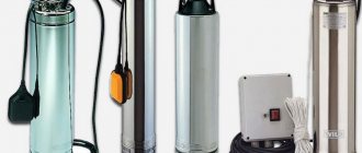
- Providing drinking water to residential buildings and industrial premises. Special submersible devices are equipped with a controller that prevents rotor rotation without liquid supply.
- Pumping petroleum products or other liquids in industrial settings or warehouses.
- Supplying a mixture of water and a special foaming agent to the fire nozzle. The units are mounted on the chassis of fire trucks, driven by the main engine through a power take-off.
- Ensuring coolant circulation in heating systems.
- Supply of water or detergent solution in washing machines and dishwashers.
- Providing water pressure in irrigation installations for agricultural purposes.
- Centrifugal pumps are used to supply coolant in heat engines (for example, internal combustion engines).
- Filling and draining water from tanks on cargo ships (ballast load to ensure stability).
- Pumping of liquids used in food production.
Purpose
In other words, a centrifugal pump is the main element of an autonomous water supply system.
Thanks to its unique design and efficient operation, pumping equipment of this type has found its application in the following areas of life:
- centrifugal water pumps are the best option for organizing technical water supply at enterprises;
- in industry, units are effectively used to move all kinds of liquids and solutions between production facilities;
- in agriculture, pumps of this type are widely used to supply water to livestock farms, and they are also used to organize watering of plants;
- municipal water supply of cities operates exclusively thanks to centrifugal units;
- in the private sector, pumping equipment of this type is an indispensable element in organizing the water supply of a summer cottage.
Knowing the wide range of applications of centrifugal pumps, a curious reader can quite reasonably ask a logical question: how do units of this type work? What is unique about their operation?
To answer these questions and understand the principle of operation of centrifugal units, first of all, you need to know what structural elements they consist of.
Connecting the pump to the control panel
- hydraulic accumulator;
- pressure gauge;
- dry run blocker;
- start protection relay.
The hydraulic accumulator accumulates water through a built-in membrane.
The dry run blocker stops the operation of the unit and prevents overheating when the supply stops.
The functions of the blocker are supplemented by a start-protection relay, the contacts of which start and stop the process of pumping liquid.
The chain pressure gauge records the pressure inside the water supply. The regulator smoothly sets the current indicators.