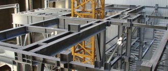
Main nuances of the process
According to technological features, the converter method is divided into two types:
- Converter processes with bottom air blast – Bessemer and Thomas processes.
- Oxygen converter process with oxygen purging from above and below.
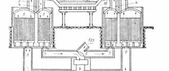
Oxygen-converter method
With air blast, the cast iron poured into the converters is blown from below with air. Due to the fact that air particles oxidize any impurities in cast iron, the temperature of the steel increases up to 1.6 thousand degrees. It is this heat that turns cast iron into steel.
Differences between the two methods
The above-mentioned production is divided into Bessemer and Thomas processes. The differences between them are in the main components of the converter linings.
The Bessemer steelmaking process allows for the use of low phosphorus and sulfur content. In the Thomas method, on the contrary, cast iron is melted using a high phosphorus content.
The essence of oxygen-converter production is the smelting of steel by lining and blowing oxygen from a liquid cast iron base. A water-cooling mold must be used for this.
Water cooling form
In the units, oxygen is supplied from below. This method is most common in Russia. Although in foreign countries a combined blowing method is often used. In metallurgy, the oxygen-converter smelting method is recognized as one of the most effective in several respects:
- Reproduction of one steel-smelting unit exceeds the power of other methods by several tons.
- In heavy-duty converters, reproduction reaches about 500 tons in 1 hour.
- The costs are significantly lower than with other production.
- Quite economical arrangement of any workshop, even regardless of the power of the melting units.
- The simplicity of the process lies in the automation of the steel smelting method.
Due to the fact that pure oxygen is used, the resulting steel does not have a high nitrogen content. This allows the material to be used in a wide range of small industries. It is also important that comparative safety for health allows the use of mid-level specialists.
Opportunity to provide employment to more people
Bessemer converter
The Bessemer process (acid lining of the converter) was developed by the Englishman G. Bessemer in 1856-1869. and allows you to process cast iron with a low content of phosphorus and sulfur and a sufficient amount of silicon. Melting in a Bessemer converter is carried out as follows. Bessemer cast iron (0.7-1.25%Si; <0.06%P; <0.06%S) is poured into the converter at a temperature of 1250 - 1300 °C and purged with air. During blowing, carbon, silicon and manganese of cast iron are oxidized and acidic slag is formed from the resulting oxides. After the carbon has oxidized to the specified content, the blowing is completed. The metal is poured through the neck into the ladle, simultaneously deoxidizing it. Since the slag is acidic, sulfur and phosphorus are not removed during melting.
Features of steel production using the oxygen-converter method
To create steel in this way, not only special equipment is used.
First of all, it is necessary to take into account the technological requirements for preparatory work.
An integral part of such work is compliance with safety regulations. It is mandatory that a labor safety engineer must periodically inspect every person employed in production. At the slightest change in working conditions, it is necessary to instruct each employee.
Converter production by oxygen purging occurs in several stages:
- scrap metal is loaded into the converter;
- cast iron raw materials are poured;
- purging of the converter contents with oxygen is switched on;
- steel waste, slag and slag-forming materials are loaded.
Converter steelmaking process
Each stage is performed only in the described sequence with the correct proportions taken into account. Scrap of any type of metal is loaded into an inclined converter tank using loading machines.
In the next step, specially installed pouring taps allow you to pour the required amount of cast iron. After this, the converter must be installed vertically and only then begin purging with oxygen. The frequency of which is not less than 99.5% O2.
Once blowing begins, it is important to load some of the slag materials. The entire volume of which, including iron ore, is distributed in several stages. It is important to observe the speed of their loading, but no later than 5–7 minutes after the first stage of smelting.
Support ring.
A general simplified view of the support ring is shown in Fig. 6.
1 - half ring; 2 - trunnion plate; 3 - axle; 4 - window for air circulation
Figure 6 – General view of the converter support ring
It is a structure consisting of two half-rings 1 and two axle plates 2 fixed between them; half rings and plates are fastened with pins. The half rings are made of welded hollow rectangular (box-shaped) sections. To protect the support ring from overheating and from drops of metal and slag above it, a protective casing 3 is welded to the converter body (see Fig. 3).
Figure 7 shows the support ring of the converter suspended from the axle by three rods (meridional).
1 — meridional thrust attachment unit; 2 - window; 3 - emphasis; 4 - trunnion plate;
5 - axle; 6 — channel in the trunnion; 7 - stiffener
Figure 7 – Converter support ring
Half rings are made by welding from sheets of non-aging steel 09G2S. Typically, the upper and lower shelves of the semiring are made of sheets 100 mm thick, and the vertical walls are 50-60 mm. To strengthen the structure, transverse stiffeners are located inside. There are holes for air circulation in the walls of the ring, as well as in the stiffeners, which help cool the half rings.
The axles are forged from alloy steel type 40ХН. They are attached to the support ring by pressing into a trunnion plate. The journals of heavy-duty converters are made water-cooled; An axial channel is provided in the trunnion for water supply.
Features and secrets of the process
This method differs from other methods of steel production in that it involves very high speeds. The entire method, as a rule, takes place in literally 14–24 minutes. High temperatures make it possible to set the instantaneous rate of dissolution of lime in slag contents.
Therefore, steel smelting in one converter, including the entire production process, does not take more than 30 minutes. It is important to note that the quality of the main process is directly affected by the uneven oxidation of each component contained in the aggregate.
The leading principle of the oxygen converter process is determined by temperature control and changing the number of blowdowns. A necessary condition for the efficiency of smelting is the introduction of coolants such as iron ore, scrap metal, and limestone.
Dust waste is cleaned using a waste heat boiler. All waste gases from the smelting process enter the installation for their purification. All oxygen steel production is controlled by powerful modern computers.
It is worth noting that with bottom blowing, the specific volume of finished steel is much less than with top blowing. It is with the bottom method that the speed of obtaining finished steel is much higher.
Technologies for producing liquid steel
In addition, as for the finished metal, after all production work is completed, the result is 1–2% more efficient.
Additionally, during the process, the duration of purging is reduced and scrap melting is accelerated. All this allows you to set up a specific technological process at a lower height of the production building.
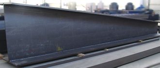
Hull and bottom.
The converter body is welded from non-aging sheet steel 09G2S with a thickness of 20 to 100 mm and is either all-welded or with a detachable bottom, which is secured with bolts or wedge joints.
The neck, more than other casing elements, is susceptible to high temperatures and warping and can be damaged when removing frozen metal splashes. Therefore, the top of the neck is protected with a massive helmet. The helmet design shown in Figure 4 has proven itself well.
Figure 4. – converter neck helmet
A thickened shell 2 equipped with an annular groove 3 is welded to the body 1 of the neck, on which several cast segments 4 are fixed using embedded strips 5. These segments are usually made of heat-resistant cast iron, to which splashes of metal (accretion) are welded less than to steel. Damaged segments (one or more) can be replaced relatively easily.
The bottom of converters is often made spherical, which facilitates metal circulation and helps reduce lining wear. Both permanent (see Fig. 3) and detachable bottoms are used. Detachable bottoms can be attached (Fig. 5, a) and plug-in (Fig. 5 b).
1 — attached bottom; 2 — converter casing; 3 - reinforcing layer of lining; 4 - working layer of lining;
5 – blocks of fused magnesite; 6 — pre-reinforcement layer (refractory mass, asbestos); 7 - fire-resistant mass; 8 — plug-in bottom
Figure 5.- Lining of oxygen converters with attached (a) and plug-in (b) bottoms
The leading principles of high-quality steel smelting
According to statistical indicators, every tenth ton of steel produced in the world is obtained as a result of the oxygen-converter method with bottom blowing.
The entire process, with low production costs and adequate working conditions, contributes to the production of high-quality steel. The unique technological capabilities of converter units allow the use of various alloy compositions, except for the liquid cast iron itself.
A certain interest in this method in industry is caused by its widespread use since the 60s of the last century. The main standard range of containers for converter units was established during the Soviet Union. The huge vessels are pear-shaped and have a volume range from 50 to 400 tons.
It should be noted that it is the size of the converter that influences the improvement of finished steel performance. The optimal specific volume of the oxygen converter promotes an intensive supply of oxygen and prevents emissions of foaming slags and metals.
One of the leading principles for the production of steel in oxygen converters is their design with a capacity of 400 to 4.3 thousand tons and a minimum height of 6–8 meters. Units that are too low provoke emissions of foaming metal through narrow necks. This fact negatively affects the entire production process and the quality of the output steel itself.
Process planning
It is also fundamentally important to carry out detailed planning of all optimal conditions before each melt. They include:
- consumption of cast iron and scrap;
- level of oxygen supply to the tuyere;
- approximate calculations for the concentration of phosphorus, sulfur and slag;
- analysis of the final steel mass and specified waste volumes.
The specific intensity of steel smelting using the oxygen method in converters makes it possible to produce high volumes of raw materials with minimal load on the process. An important role here is played by the design and selection of accompanying conditions, as well as the organization of production technology.
High-quality steel in the country is produced not only in huge factories, but also in small premises; efficient production requires the necessary power of units and qualified specialists.
General information about converter shops
A modern oxygen converter shop is a complex complex of interconnected buildings and structures equipped with a variety of equipment, in which stock of charge materials is stored, fed and loaded into the converter, steel is smelted and cast, and smelting products are removed. The workshop includes a number of main production and auxiliary departments, located either in separate buildings or in the bays of one building.
The work of modern newly constructed and reconstructed workshops is characterized by the use of steel-smelting units of large unit capacity; intensification of the steel smelting process, the predominant use of continuous steel casting; high level of mechanization of production processes; automation of workshop management and individual production processes and areas; the use of catching and cleaning devices to prevent environmental pollution. In recent years, the use of various methods of out-of-furnace processing and refining of liquid steel has been expanding. Steel-smelting units are increasingly beginning to be used only for melting metal, heating it to the required temperature and oxidizing carbon in the metal to specified limits; bringing the composition of the metal to the specified level for other elements, deoxidation and refining from harmful impurities are transferred to the ladle.
There are more than 250 workshops in the world with converters of various capacities (in Russia there are 8 workshops).
The differences between the workshops are primarily due to changes in production volume, the range of steel produced, and the specifics of the plant’s general plan. Attempts made in the country and abroad to reuse the developed workshop designs due to technocenological limitations were not crowned with success. Although all workshops in the world were built according to individual projects, studying the results of construction and operation makes it possible to identify some patterns common to most known facilities.
Performance indicators of converter shops
The composition of the workshop, the number and type of departments and buildings included in it depend on the type of steelmaking process, on the adopted method of casting steel and on whether the departments are interlocked with each other or not. When choosing the number of departments and buildings, it is taken into account that it is advisable to design the workshop in accordance with the principle of continuous production, transferring individual operations and elements of the technological process to specialized departments, in which high labor productivity is ensured by performing similar work.
It is also taken into account that the location of specialized departments in separate buildings ensures improved working conditions due to the absence in many departments of hazards associated with the presence of liquid metal and the operation of melting units, as well as due to improved aeration of separate buildings.
With such a layout, with an increase in the number of separate buildings and especially when railway transport is used for communication between them, the area occupied by the workshop increases significantly. Currently, due to the need to save areas suitable for agriculture, the task is to develop a more compact layout with a reduction in the number of individual buildings (by blocking departments, organizing work in specialized bays of the main building).
At the same time, it is necessary to develop special measures to improve working conditions in a multi-bay building (insulation of melting units with the capture of released harmful substances, installation of local suction in places where dust, heat, harmful gases are released, etc.).
The converter shop is located on the territory of the metallurgical plant, taking into account the direction of the “wind rose”. In order to reduce air pollution above the plant, the workshop is located on the leeward side.
The workshop is also located taking into account the main direction of the plant's transport routes. At most factories, the delivery of raw materials to the main workshops and the harvesting of products is carried out by rail and the tracks through the plant are laid mainly in one direction. The location of the workshop and its paths should create a minimum of interference with general traffic flows. The converter shop is located along the direction of the main tracks or can be located in the transverse direction, due to their relatively short length.
The main lines of the converter shop's cargo flow system are; delivery and filling of liquid cast iron, delivery and loading of scrap; delivery and loading of bulk materials into the converter; delivery and loading of ferroalloys into a ladle, often with their heating or melting; transportation of ladles with liquid steel; pouring and cleaning of ingots or castings; slag removal; delivery of materials for the repair of converters and other equipment and garbage collection.
The diagram of the main cargo flows of the converter shop is shown in Figure 1.
Figure 1. – Scheme of cargo flows of a modern converter shop
Scrap metal is transported by rail to the magnetic materials department and loaded into receiving bins. The scoops are filled with scrap metal using magnetic grab cranes 28. The loaded scoops are weighed and installed on a scrap truck 1, which delivers them to the work site or loading bay. Filling of scrap metal into the converter 3 is carried out by loading machine 4.
Liquid cast iron is supplied and poured into the converter in two ways, determined by the type of mixers used - stationary or mobile.
In the first case, cast iron is delivered in the ladle of cast iron carriers 13 from the blast furnace shop to smelter department IV and is poured by crane into a stationary mixer 12. If necessary, cast iron is released from the mixer into the ladle of self-propelled cast iron carriers 11, transporting it into the loading bay to the converters. The cast iron is poured using a filling valve 10. In the second case, the cast iron is supplied by mobile mixers 14 to the overflow compartment IV, in which the pouring ladles are filled. The ladles are transported to the main building by self-propelled cast iron carriers 15, and cast iron is poured by pouring cranes 10.
Bulk materials are delivered to. charge separation of ΙΙ non-magnetic materials by rail or road transport. Materials from railway gondola cars 30 are unloaded into receiving hoppers 29 with subsequent delivery by electric vibrating feeders. Materials are supplied to the consumable bins 9 of the converter housing ΙΙΙ by an inclined conveyor path 7 and reversible mobile conveyors 8. The weight dosing and supply system 6, consisting of vibrating feeders, weighing dispensers, conveyors, intermediate bins and chutes, ensures the loading of certain portions of slag-forming materials into the converter in smelting process.
Technically pure oxygen is supplied to the converter by machine 5 through an oxygen lance. Supply is carried out via the main line from the oxygen workshop.
Delivery of ferroalloys to the main building of the workshop is carried out by road or rail in containers, or a conveyor path for supplying bulk materials is used. In the first case, containers with ferroalloys are unloaded by crane into consumable bins 16. Weighed portions of ferroalloys are heated in chamber furnaces 17 and, via chute 18, fed into a steel-pouring ladle on a steel truck. In the second case, ferroalloys are delivered in railway cars to the ferroalloys department, directly adjacent to the bulk materials department. From the receiving bins, ferroalloys are delivered to the belt conveyors of the bulk materials supply path, which fill the consumable bins in the main building.
In converter shops, two main casting methods are used - into molds mounted on trolleys, and on continuous casting machines (CCMs). In all cases, the steel is poured from the converter into a steel-pouring ladle mounted on a steel truck 19. In the first method, the ladle with steel is transferred by a steel truck to a separate casting compartment V or to casting bays adjacent to the main building. The molds are filled with liquid metal from a ladle moved by a casting crane 20 over a composition 21 with molds. After solidification and complete crystallization of the ingots, the compositions with molds are delivered by locomotive to stripper compartment VI to remove profitable extensions and blast the ingots with the widening upward. Molds with widening downward are removed from the carts and sent to prepare for the next filling. All operations are performed with a stripper tap 22. Then the composition is fed into the heating compartment VII of the crimping mill, in which the ingots are installed in heating wells, and the composition with molds is sent to the Dusting Unit VIII. After cooling, the molds enter department IX for cleaning and lubrication, and then to department X for preparation of compositions, where cleaning work is carried out and installation of pallets, centerpieces, profit extensions, etc. on trolleys is carried out. The prepared compositions are again fed to the pouring department. The molds perform a closed cycle of work and preparation.
According to the second method, the steel-pouring ladle is fed by a steel truck into the continuous casting department V and installed by a casting crane on stand 23. The billets produced by continuous caster 24 are supplied to the rolling shop.
The slag from the converter is poured into the ladle of a self-propelled slag carrier 2 and transferred first to the slag span of the main building to move the bowl to the harvesting slag carrier 26, and then sent to the slag compartment XΙ for cooling and subsequent crushing by blows of the woman lifted by crane 27. The processed slag is shipped to the dump by dump cars 25.
The layout of the main lines of cargo flows, the relative location and number of workshop departments, and the layout of the main building in existing workshops are very diverse. This is largely due to the fact that the operating experience of converter shops is short-lived and, as it accumulates, planning solutions continue to be improved; This is also explained by the fact that many foreign converter shops used forced design solutions, since they were built in conditions of cramped space, existing cargo flows and using the buildings of pre-existing workshops.
Railway, road, conveyor transport, roller conveyors, pipeline transport are used as intra-shop and inter-shop transport; Rail carts and cranes are also used for intra-shop transportation. Transport design includes the following main stages, calculation of the volume of inter-shop and intra-shop cargo turnover, selection of the type of transport, the actual design of the transport system, including determining the required number of vehicles.
The volume of cargo turnover is calculated based on the known productivity of the workshop and the consumption coefficients of materials per 1 ton of steel or cast iron. The type of transport is selected taking into account the volume of transportation, the type of cargo transported, the nature and conditions of the technological process, and based on a comparison of the efficiency of a particular transport in the specific conditions of the workshop. Currently, at metallurgical plants, 72% of inter-shop transportation is carried out by rail; For new workshops and when reconstructing existing ones, it is recommended, where possible, to use other, more economical modes of transport.
The main advantage of railway transport is its versatility, which allows the transportation of almost all types of cargo, including liquid metal and slag. It is also important for metallurgical shops that over many years of operation, well-proven special types of rolling stock have been created - iron carriers, slag carriers, etc.
The disadvantages of this type of transport are the relatively low efficiency and flexibility and the fact that the construction and operation of railways require relatively large capital costs, operating costs, labor costs and land area occupied.
When transporting over short distances, road transport requires lower specific capital investments, operating costs, and labor costs compared to railway transport. In addition, the area occupied by transport is reduced by 4-5 times; for vehicles, we allow twice the slope of the tracks; characterized by greater maneuverability (the permissible radius of curvature of tracks is 6-7 times less than that of railway tracks); unloading is possible without the use of workshop lifting and transport vehicles.
Conveyor transport is used for transporting bulk and lumpy cargo. Compared to rail and road, it allows you to automate the transportation and unloading of materials, allows the intersection of cargo flows, requires less space and operating costs, fewer maintenance personnel, allows you to supply cargo directly to the consumer unit, which reduces the number of overloads and the mechanisms required for this. Roller conveyors are suitable only for transporting specific loads, for example, slabs from ONRS to the rolling shop.
Inside industrial buildings, the rational organization of cargo flows is ensured by a combination of floor transport - rail and, less often, motor transport, conveyor transport and the operation of overhead cranes, which allow the movement of cargo in any direction and regardless of floor transport.
Overhead cranes play a very important role in ensuring the smooth operation of many departments of steelmaking shops. With the help of cranes, cast iron is poured, scrap is loaded, steel-pouring and slag ladles are transported, repairs and many other works are carried out.
For new workshops, the following ratios between the capacity of the melting unit and the capacity of the ladles and the lifting capacity of the cranes are recommended:
When designing converter shops, taking into account these factors, it is advisable to install converters of maximum capacity. Increasing the converter capacity improves the technical and economic performance of the workshop; productivity increases, specific energy costs, refractories of some smelting materials and, accordingly, the cost of steel, as well as specific heat losses are reduced, allowing for an increase in the share of scrap in the metal charge.
For small-capacity workshops, the installation of one or two large units that ensure the implementation of the entire workshop program is, as a rule, not recommended, since this leads to underutilization of the equipment and complications in the work of adjacent workshops and departments when the converter is stopped for repairs.
The capacity of the converters selected in the project must also be coordinated with the capacity of existing steel-pouring ladles and especially with the load-carrying capacity of existing filling and casting taps.
So for each given workshop productivity and other conditions indicated above, it is necessary to select the most rational capacity of converters and their number. The capacity of converters varies widely and reaches 400 tons. The most widely used are converters with a capacity of 100 ... 350 tons. GOST 20.067-74 provides for a number of converter capacities for steel smelting: 50, 100, 130, 160, 200, 250, 300, 350, 400 t.
When selecting converter capacity for a given performance, dependencies are recommended.
Dependence of converter capacity on workshop productivity
The productivity of the converter and workshop can be represented by the liquid steel poured into the steel ladle or by suitable ingots.
The productivity of casting shops is given for casting steel into slabs. The average loss of liquid steel during casting at the ONLZ is assumed to be 5%.
Recommended converter productivity, million tons per year
In modern steelmaking shops, various methods of processing and refining liquid metal after its release from the furnace are widely used: purging with neutral gases and powdered materials, evacuation, deoxidation and bringing to the desired composition and temperature, treatment with synthetic slags and a number of combined processing methods. The use of these methods does not make fundamental changes to the workshop layout, but requires appropriate design developments. In this case, it is necessary: selection of the method of out-of-furnace processing and the optimal design of the corresponding units or stands and their number; choosing the optimal way to place them; additional areas for their placement and the creation of repair areas for relevant equipment, taking into account the increased complexity of cargo flows associated with the transportation of buckets to units; taking into account the increased workload of cranes that most often transport buckets; development of a system for supplying ferroalloys to units and stands.
The method of out-of-furnace processing is chosen taking into account the range of steel being produced and the requirements for its quality.
Yield rate of ingots from liquid steel