Metal drawing and its types
Main types of rotary metal drawing:
Step molding
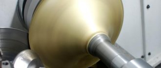
A sheet blank in the shape of a circle is fixed between the mandrel and the support. The mandrel must match the internal configuration of the product. The drive begins to rotate the blank, and controlled forming pressure is carried out by a special passive roller driven by the rotation of the blank. Pressure is applied in both longitudinal and radial planes. The roller presses the metal against the mandrel and moves along a complex curve, either towards the edge of the blank or back.
The clamping is carried out in several passes, in steps. At the end of the treatment, a series of smoothing movements of the roller are carried out with reduced pressure to obtain a high-quality surface.
Projection - One-Pass Molding
Extraction is carried out in one pass. The roller moves parallel to the mandrel, depending on the angle of its installation, the wall of the blank is thinned more or less, its material moves under the influence of the roller in the axial direction.
Projection - One-Pass Molding
The method is characterized by efficiency and dimensional accuracy, as well as a high class of the resulting surface.
Rolling with or without mandrel
In this case, the outer diameter of the workpiece is reduced with a simultaneous thickening of its wall due to the redistribution of the material. Rolling is carried out towards the center, in several passes.
Rolling with or without mandrel
As an option, the part is formed by individual segments of the mandrel using a roller with an offset center. Cutting, additional profiling or flanging are carried out as final operations.
Combined
For parts with complex configurations, stepwise forming, rolling, profiling and cutting are used together in various combinations.
Mechanical parameters and basic circuits
Metal cutting: technologies used
The worker must take into account many technological parameters of the operation, since an accidental deviation from the norm may significantly change the technical parameters of the processing, which will lead to a violation of the accuracy of the procedure.
Preload
One of the main parameters is tension. From a technical point of view, interference is the difference between the dimensions of the original hole and the mandrel tool (usually this indicator is measured in millimeters, and the diameter of the pipe and the diameter of the mandrel are used as the measurement object). If the interference is too large (that is, the mandrel and the hole are very different in size), then it will be problematic to make a smooth, hard surface. Also, when processing, you need to take into account some features of the material from which the pipe is made - ductility, hardness, and so on.
Force
In addition to the tension, the force of the burnishing is of great importance, which means this parameter means the intensity of the hole machining
Please note that there are two types of mandrel force - radial and axial. By radial force we mean the degree of influence of the mandrel in the perpendicular direction. This indicator reflects the degree of expansion of the pipe diameter during processing
This indicator reflects the degree of expansion of the pipe diameter during processing.
Axial force refers to the impact of a tool along its axis. The higher this indicator is, the easier it will be for the mandrel to cut off various roughnesses
Also note that relative deformation must be taken into account when processing. This indicator reflects the degree of increase in the outer part of the part
Scheme selection
Also, before processing, it is necessary to choose a mandrel method - the tensile method, the compression method or a combined method. Each technology has its pros and cons.
The most popular is a combined tension-compression method. What is the reason for its popularity? It does not create the excessive axial loads associated with conventional tension or compression methods. Thanks to this, processing is carried out smoothly, which avoids mechanical damage.
However, it must be remembered that the combined method scheme requires special equipment, which is quite expensive. To burnish a pipe at home, you should choose an alternative method.
Rotary metal drawing process
As a rule, a sheet plate in the shape of a circle is used as a blank. In addition, for some parts other flat shapes are used - an oval or an ellipse, as well as complex curvilinear closed contours. Blanks are also used - sections of pipes, most often round.
Preparatory operations for unique parts and small series are performed on round cutters. In the case of large series, cutting is more efficiently performed on hydraulic cutting machines, due to the fact that laser or plasma cutting is associated with high temperature exposure in the cutting area. This may impair the ductility of the material.
Calculation of drawing force
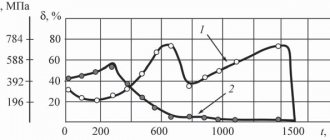
Drawing hollow round parts from a flat workpiece is a non-stationary deformation process. Due to the significant complexity of the analytical formulas for calculating the drawing force on the devil. 209 shows a graphical method for calculating the force for drawing cylindrical hollow parts with a clamp from a flat workpiece without thinning the material.
Crap. 209
At the top right in square I the values of the average deformation resistance Sav It also shows the relationship between the value of the elongation coefficient m1 and the value of true deformation, as well as with the value (Conditional deformation). Curves of average resistance to deformation Sav of aluminum, copper, brass and steel were plotted based on data from hardening curves.
where Sφ is resistance to deformation taking into account hardening at the corresponding magnitude of deformation, kgf/mm 2;
σт - yield point, kgf/mm 2.
The values of Sφ and σт are taken from experimental data.
At the top left in square II there are inclined straight lines indicating the initial thickness of the material s=0.2÷8 mm;
At the bottom left in square III there are inclined straight lines indicating the diameter of the hood d1= 10÷1000 mm;
At the bottom right in square IV there are inclined straight lines indicating the drawing force P = 0.4 ÷ 160 tf.
Below are examples of determining the forces of the 1st drawing operation according to the schedule (Fig. 209).
Example 1. Given: Dз=29 mm; d1= 16 mm; s=1 mm. Material: steel strip containing 0.06% C..
Draw coefficient (starting point A) on the line. 209.
We draw a dotted vertical line from point A to the intersection at point B with the hardening curve of steel 0.06% C. We draw a horizontal line to the intersection with an inclined straight line corresponding to a thickness of 1 mm (point C). We draw a vertical line until it intersects with an inclined straight line corresponding to the diameter of the hood d1 = 16 mm (point E). Draw a horizontal line to the right from point E to the intersection with a vertical line drawn through the starting point A.
Methods for rotary drawing of metal
The variety of techniques for rotary drawing of metal comes down to one of two types:
- Straight. The metal moves along the forming roller.
- Back. The metal moves against the movement of the forming roller.
Direct method
The outer contour of the punch corresponds to the inner contour of the future product (taking into account the necessary allowances). Because of this, the mandrel is made longer than the product. The design of the punch becomes more complicated, the weight, cost and labor intensity of debugging the technological process increases.
Direct method of rotary drawing of metal
This method is applicable for molding parts in the form of a cone and cylinder with a large ratio of length to diameter and diameter to wall thickness.
Back
In this case, the mandrel must match in size and shape with the inner surface of the workpiece, which makes it possible to make the mandrel much shorter than the future product.
Thick-walled rotary hood
The method is used in the production of products with a small length-to-diameter ratio and relatively thick walls.
Rotary metal drawing operations are also divided into forming:
- With thinning, the outer size is maintained, the wall thickness is reduced.
- Without thinning - the wall thickness is maintained during processing, but the outer diameter changes.
- With rolling, the outer diameter is maintained, the wall thickness increases.
Main types of rotary metal drawing
The workpiece is secured between the mandrel fixed to the drive and the caliper clamp.
TruMAX - an innovative approach to production
If you are looking for enterprises that perform rotary metal drawing in St. Petersburg, contact TruMAX!
- We have extensive experience in the field of metal processing: our designers, designers and operating personnel are masters of their craft.
- Considering the scope of application of our products, we use only high-quality materials in production.
- Aesthetic appearance and long service life are important to us, so all parts are carefully processed according to your technical specifications.
- We respect your time, so we complete your order within the agreed time frame.
- The client's wishes are law for us. We can carry out rotational metal drawing to order according to the provided drawings.
- Our production facilities are equipped with modern high-tech equipment. This allows you to complete any order quickly and efficiently.
- We do not forget about the environment, so our enterprise was built in accordance with European standards and requirements.
You can contact us in several ways:
- by phone numbers listed on our website;
- by visiting our sales office;
- by sending a request to an email address;
- by filling out a special form on the official website.
We will answer all questions, carry out a preliminary calculation of the cost of the service and easily bring your ideas to life.
Machines for rotary drawing of metal
To implement the technology, the following types of machines are used:
- Pressing and rolling machines for rotary drawing of metal.
- Rotary forging machines.
- Round cutters.
On manual lathes, molding is performed by the muscular strength of the worker. Used to produce unique products or especially small series. For medium and large series, pressing and rolling (rolling) machines with numerical control are used. Hydraulics or electric drives, controlled by a controller according to a program loaded into the central CNC unit, allow precise control of the force and direction of the clamp, as well as the direction of movement of the roller, including the most complex curved trajectories. Such machines ensure absolute identity of products in a series, which is especially important for jet engine parts and other high-tech products
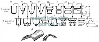
Scheme of forging on rotary machines
Rotary forging machines allow you to form conical-shaped products from pipes by crimping the pipe with a special tool - a forging die. The peculiarity and main advantage lies in the unique ability to produce products that have:
- the length is many times greater than the diameter.
- along the length, the diameter and opening angle of the cone can be repeatedly changed.
- knurling of stiffeners is required.
Circular cutters are designed for cutting rolled sheets into flat pieces in the shape of a circle or ellipse. Also used are both manual and electro-hydraulic.
Spinning lathe
A rotary drawing machine, or as it is also called a lathe-spinning machine, is designed for the manufacture of various thin-walled parts that are bodies of rotation, obtained from sheet or hollow workpieces and the corresponding material. The rotary drawing machine allows us to produce a wide range of competitive products, ranging from decorative products to products for the space industry.
Rotary drawing differs from stamping and has its own characteristics. The workpieces for processing on lathes are any viscous material, it can be: aluminum, copper, brass. You can also use annealed low-carbon steels, kovar, stainless steel, etc.
The design of a spinning lathe is very similar to an ordinary lathe, but unlike the latter, it does not have a feed box and a caliper. Instead of a tool holder, the lathe-spinning machine is equipped with a support for special “press” tools, if we are talking about ordinary mechanical equipment.
In addition to manual lathes, industry in advanced countries produces universal machines equipped with numerical control systems, in which the processing process is fully automated. As a rule, rolling on such machines is carried out with rollers.
Rotary drawing is carried out on lathes of various capacities, which make it possible to produce a wide range of products, from musical cymbals and bells for wind instruments, to the bottoms of tanks and containers used for storing liquids installed in railway and road transport.
With the help of high-performance lathes, various products are produced, such as: head fairings of the front parts of rockets, airplanes and other fast-moving objects that provide the least aerodynamic drag, satellite antennas that provide high-quality signal reception and transmission. These machines produce light reflectors, which, after running in, take on a spherical or conical shape and are used to illuminate factory areas, shops and other premises. Reflectors can also be decorative, which in addition to lighting have a pleasant appearance and serve as a worthy addition to the interior.
Rotary drawing technology allows you to reduce the cost of serial and small-scale production of some machine parts, for example, pulleys, which are usually turned from a workpiece (round blank), they can also be rolled on a lathe, which is much faster in production speed and more economical in metal consumption . The parts can also be various casings, flanges, guides, thin-walled vessels of a special shape, overhead cones, etc.
But the main direction of lathes and presses is, of course, the production of consumer goods: saucepans, which are constantly in demand, mugs that are daily necessary in everyday life, decorative trays and stands, plates, bowls for eating, thermoses that keep the contents warm, and much more.
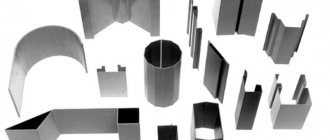
Scope of application of rotary metal drawing
The method is used to produce:
- jet engine parts in weapons systems;
- tank bottoms and covers;
- various screens in radio engineering, including radar screens;
- thin-walled vessels of complex shape: cans, teapots, cylinders, kettles;
- parts of construction mixer bodies;
- parts of fans and exhaust hoods.
Products made by rotary drawing
The method is also used in the production of contemporary art objects and in the studio for customizing unique motorcycles and cars.
What are the features of CNC pressing and rolling machine?
Would you like to know more about CNC press-forming machines? Find out about rotary hoods, classification, features and advantages of such units.
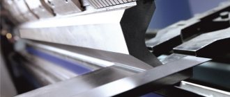
Pressing and rolling machines with numerical control are equipment used for processing sheet metal blanks. Pressing and rolling processing of a roller is a modern method carried out on CNC pressing and rolling machines.
This method involves the use of devices that have hydraulic and electro-hydraulic supporting parts of the metal-cutting device. They move the pressure rollers, which are the main tools in the processing of parts.
What is a rotary hood
A method for processing sheet-type metal products, in which a three-dimensional part is transformed into a hollow one with an axisymmetric appearance, is called rotary drawing. It involves significant deformation and thinning of the walls of the spare parts. This method of processing sheet metal by drawing has ancient roots. In modern manipulation of steel blanks, it is carried out by a pressing and rolling machine.
Using the rotary drawing method, these devices are capable of producing household items with thin walls and complex shapes. A set of such devices is presented:
- teapots;
- scoops;
- sponges;
- vessels;
- coffee pots.
Characteristics of sheet stamping
Cold sheet stamping is today one of the most widespread technologies for processing metals, plastics and some other materials. The range of application of the technology is from large structures in shipbuilding to thin-walled parts of household appliances
The technology is characterized by the following undeniable advantages:
- Exceptional opportunities for mechanization and automation of production processes.
- Reducing the cost of manufacturing mass products.
- High utilization rate of sheet metal.
- The ability to accurately manufacture thin-walled but durable products of almost any shape.
- Minimal need for subsequent machining.
However, in addition to obvious advantages, cold sheet metal stamping also has disadvantages. This is, first of all:
- High complexity of technological process design.
- High cost of preparation for production of molds.
- Highly qualified press equipment debuggers.
Sheet metal stamping
It should be noted that with large series of manufactured products, these disadvantages are leveled out due to the economies of scale known from economics, and the cost of manufactured products turns out to be lower than with alternative methods of metal processing.
Classification of CNC machine tools
Pressure-rotary drawing has many of the properties and functions of turning analogues. In contrast, pressure-rotary devices have a higher operating speed. There are three types of devices of this type:
- manual tabletop;
- manual floor;
- with a rotary hood.
Rotary drawing is accompanied by additional actions such as rolling, expanding and welding. The rolling machine is capable of both producing a solid part using the rolling method, and completing the drawing and production of spare parts made using other equipment. The most popular products of this kind, for example, are tubular spare parts with various combinations of cross-sections.
The machines can be used not only for processing metal parts, but also copper ones that have a conical shape. The advantage of CNC devices is that the process is less labor-intensive than using presses. Modern technologies make it possible to monitor the operation of devices remotely. Round metal plates are used as the main raw material for working on a rotary pressing machine.
But the devices can also cope with workpieces that have a more complex geometric shape. Additional methods of working with the product are circular and hydrojet cutting. Examples of plasma and laser cutting in this case are less effective, since they can increase the temperature, which will change the plastic qualities of the spare part.
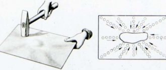
Rotational-local shaping of products with complex profiles from sheet material
The method of forming products with a complex profile from sheet material by local deformation is carried out as follows (Fig. 1).
Sheet blank 1, intended for the manufacture of a product of complex shape, is subjected to local deformation by tool 2, which is installed with the ability to move along three coordinates. The tool moves sequentially along specified trajectories. At each point, the tool is located tangential to the path and perpendicular to the surface of the workpiece. In these directions, under the action of force P, local deformation occurs. A plane stress state arises in the deformation zone, and the deformation zone is surrounded by elastically deformed zones.
Figure 1 – Generalized diagram of the implementation of the method of local processing of sheet material : 1 – sheet blank; 2 – tool; 3 – tool movement trajectory; 4 – tangent to the trajectory
Local deformation can be carried out: with one movable tool; between the movable tool and the fixed matrix; between the rotating mandrel and the moving tool; between two movable instruments (Fig. 2). Processing of sheet materials with one moving tool is technologically limited to simple-shaped products. The use of an additional permanently fixed matrix expands the possibility of local deformation, but the cost of technological equipment increases. The method of local processing of a sheet blank between a rotating mandrel and a movable tool (rotary drawing) has found wide application. Development and technological research is being intensively carried out to develop technologies and create equipment for the widespread use of two moving tools.
Figure 2 – Technological schemes for implementing processes of local processing of sheet material : a – with one movable tool, b – between a movable tool and a fixed matrix; c – between the movable mandrel and the movable tool (rotary hood); d – between two movable tools; 1 – fastening; 2 – tool; 3 – workpiece; 4 – matrix; 5 – mandrel
Figure 3 shows a design diagram of a specialized experimental setup for shaping products of complex shapes using two movable tools. The upper 13 and lower 10 movable tools are installed coaxially in a C-shaped frame 1 with the possibility of vertical movements. The C-shaped frame is fixed to the supporting carriage 7 and, with the help of side carriages 3, 9, moves in a horizontal plane along guides 5, 8. The force of the supporting carriage is perceived by a ball bearing 6 mounted on the foundation plate 4.
The sheet workpiece is placed on a horizontal table and secured with clamps 2. The upper and lower tools are respectively located on both sides of the workpiece.
The shaping of the surface of the workpiece is carried out in the process of joint movements of the C-shaped frame and tools. The motion trajectory and processing modes are set automatically.
Figure 3 – Scheme of a specialized installation for double-sided shaping : 1 – C-shaped frame; 2 – clamp; 3, 9 – carriages; 4 – foundation slab; 5, 8 – guides along the X, Y axes; 6 – ball bearing; 7 – supporting carriage; 10, 13 – lower and upper tools; 11 – table; 12 – sheet blank
It seems very promising to carry out rotational-local shaping under the influence of the electroplastic effect. To do this, the upper and lower movable instruments are connected to a pulse current generator. The tools move towards each other and locally compress the sheet workpiece. When the yield strength of the workpiece material is reached, a pulsed current is passed through the electrodes with a frequency of 100 Hz, a pulse duration of 200 μs, and a current strength of the order of 2000...3000 A. Under the influence of current pulses, local heating and local softening of the workpiece material occurs.
As a result:
- springing of the workpiece is eliminated due to the removal of internal stresses;
- there is no need for intermediate annealing, which means energy saving;
- the unevenness of deformation is reduced and the formation of cracks and tears is eliminated;
- the residual plasticity of the workpiece material increases.
In order to reduce time and money for creating specialized installations, the shaping of products with complex shapes can be carried out using two robots (Fig. 4). The sheet blank is secured in a vertical position with 2 clamps 3. Robots 1, 4 are placed on both sides of the workpiece. Processing tools are fixed in the working parts of the robots. The shaping process is carried out by synchronous movements along a complex trajectory of both tools. Such a shaping system requires precise adjustment of both robots and coordination of their movements.
Figure 4 – Scheme of shaping by two robots : 1, 4 – robots; 2 – sheet blank; 3 – clamp; 5, 6 – tools
The processes of forming products of complex shape using local deformation methods are at the stage of intensive research and development. The results obtained open up broad prospects for practical application (Fig. 5). The processes can be successfully used for the manufacture of complex-shaped bodies of cars, electric trains, ships, airplanes, etc.
Figure 5 – Current and potential applications of local shaping : 1 – prototypes and component design; 2 – spare parts; 3 – aircraft manufacturing; 4 – automotive industry; 5 – economic and technological areas of application of local shaping
The use of rotational-local forming technologies compared to conventional stamping will approximately provide:
- reduction in energy intensity of production by 4–6 times;
- reduction in manufacturing labor intensity by 4–5 times;
- reduction in metal intensity of production by 17–30 times;
- elimination of the use of stamping equipment;
- possibility of full automation of production and control of products.
Advantages of machines of this type
All types of rotary pressing machines have the same principle of use. The roller tool is the most commonly used. When working with this equipment, it is possible to produce unique spare parts of complex shapes, while simultaneously carrying out equipment. The machine is equipped at a low price. For other types of metal manipulation, the price of equipment will be significantly higher.
Among the main advantages of units with a rotary hood are:
- possibility of mass, small-scale and single production;
- possibility of operation in large and small workshops;
- possibility of manufacturing wooden equipment;
- production of parts for the economic, chemical and food industries;
- economical use.
Features of the package
Models of CNC machines have a high productivity rate. Thanks to numerical control, they have an automatic production mode. By using such a machine, you can provide yourself with a number of advantages. One of them is the presence of two tool rollers, which simultaneously exert increased pressure.
The configuration of the above models consists of examples:
- circle-centering device;
- optional manipulator;
- double type tool head;
- 4+4 positioning mechanism;
- hydroelectric power stations;
- additional roller with a compensator.
The thickness of aluminum blanks for processing should be from 0.6 to 4 millimeters. For steel blanks - from 0.6 to 2.5 millimeters. For workpieces made of corrosion-resistant steel - from 0.6 to 1.5 millimeters. The specified characteristics are relevant only for original models.