How to make a locator with your own hands
Citizen K. had long dreamed of settling somewhere in nature, far from the noisy bustling civilization of a big city, among the peace and quiet of the harmony of the world. And so his dream came true: he bought a small plot of land on the outskirts of the village for construction, in a good location and even with a small abandoned garden... but then he had to face such a problematic issue as finding pipe routes and cable lines, without knowing where are they located:
- During construction, you can damage them, and if the cable is live, you can put your own life at risk;
- You can forget about connecting to electricity, gas and water supply, without knowing where it runs.
But how to find these unfortunate lines? Tear up all the soil and search at random. Not at all! You just need to turn to the help of such a useful device as a locator, which allows you to find lines quickly and safely. Today the device can be purchased in every specialized store; you can make a locator with your own hands. And we will tell you how later. But first, it’s worth figuring out what kind of device this is, a locator.
Question 7. How to narrow the search area for the location of damage?
In many ways, the accuracy of leak localization is determined by the characteristics of the soil. Therefore, a situation arises when, at a fairly significant distance from the location of the actual damage, the values of the leak detector readings practically do not change. This is caused by the presence of a capacitive component in the leakage value.
Solution 1 . Line defect detectors TDI-05M-3, TDI-MA can be switched to operating mode at a lower frequency - 893 Hz. This will largely filter out capacitive leakage.
Solution 2 . The TDI-MA digital fault detector has an infra-low operating frequency of 7Hz, which allows you to narrow the leak search area as much as possible.
A little theory
So, a route finder is a unique device that allows you to detect a cable line or pipes. Modern devices are divided into two types based on their operating principle;
- Contact principle;
- Induction variety.
The contact principle is used in the event of a break in a live cable.
The device, operating on the induction principle, is capable of detecting both live cables and passive tracing, that is, underground communications that do not produce active signals. The induction method is more complex and is based on the device capturing high frequencies and recording these indicators on a special indicator.
Locators are also divided into single- and multi-frequency. The first is the most acceptable option; such devices are easy to install yourself, and they are used to determine communications located underground in the case when some routes do not intersect others, and thus the signals emanating from them do not overlap.
Multi-frequency devices are a more complex design and are used to determine route signals in cases of high density cable lines and pipelines. Multifrequency devices are able to determine the frequency specified in the program without straying to others. Modern devices are equipped with software, which greatly facilitates the work, which for the user consists of one press of a key and reading the received information displayed on the indicator.
For information about the purpose of route finders in horizontal directional drilling and methods for searching for routes and cables, see here. The purpose of casing pipes, their scope of application, manufacturers and selection rules are described here.
Devices for finding hidden wiring: an overview of models and functions for the home handyman
Experienced electricians know well that a hammer drill quite accurately finds live cables hidden in the wall, as well as pipelines with hot water pressure.
This property causes a lot of trouble for inexperienced workers. Devices for finding hidden wiring are designed to prevent such cases.
They are produced in a large assortment with a different set of functions for regular use by professional craftsmen or rare use by home craftsmen. I suggest you read a brief overview of their capabilities.
What are the principles of devices for finding hidden wiring?
The industry produces 3 types of such devices for the modern electrician, which are usually divided as:
- locators;
- electromagnetic field indicators;
- detectors for detecting hidden wiring.
They are created for specific application conditions and have different technical capabilities.
How modern locators work
As an example, let’s look at the operation of the Mastech MS6812 cable tester-router. It is most often used to detect the location of a cable break in closed wiring and consists of two autonomous parts:
- Tone generator cable pressor (Cable tracker), which produces high-frequency signals. Its output is connected to the cable being tested, the route of which must be clarified.
- A cable tracker signal receiver that emits specific sound signals indicating the location of the cable when it is placed in the search area.
Cable tracker tone generator Cable tracker signal receiver
To connect the generator, first determine the broken core by testing the cable with a digital multimeter. A high-frequency signal is supplied to it and the ground loop.
If you just need to determine the cable route, then connect a generator to the whole core and the ground circuit. In this case, in most cases, external power must be removed from the circuit under test.
The high-frequency radiation is picked up by the tracker's receiver, which produces a clearly audible single-tone continuous whistle. If desired, it can be changed to a two-tone euk, which is better heard in industrial noise conditions. To do this, use the switch built inside the case.
The receiver is led along the route of the laid cable, guided by the sound of the speaker. When the damage is reached, the sound disappears. They are looking for a cliff in this area. The method is very accurate.
To ensure reliable searching, it is recommended to switch the generator to the opposite end of the cable, and then pass the receiver from the opposite side to the same place.
Both the generator and the receiver are powered by their own batteries, which ensures their independent operation.
The locator from Proskit and many other manufacturers works similarly.
More complex cable defects, when it is crushed with a violation of the insulation and cross-section of the cores, but without a break or short circuit, can be determined with an ohmmeter and megohmmeter. However, it will be difficult to determine the exact location of the damage.
Professional route finders, depending on the design, are capable of finding cables hidden in walls up to 40 cm and up to 2.5 meters buried in the ground. But they are expensive.
For home use, it is quite possible to use the budget device Mastech MS6812. It copes well not only with electrical wiring, but also with low-current alarm circuits, video surveillance, antenna devices, computer systems and other similar devices.
Designs of homemade route finders
Home craftsmen with amateur radio skills use their high-frequency generators, directing their signal to damaged wiring. They are tuned to the frequency of a VHF receiver or smartphone and with their help they successfully search for cable defects.
The method requires skills and special equipment, and is not reliable in all cases.
How simple electromagnetic field indicators work
To detect hidden wiring, the property of electric current to propagate an electromagnetic field in the surrounding space is often used. It is detected by indicators of various designs.
The simplest version of such a device is represented by an indicator screwdriver.
Just keep in mind that they are produced with different circuits for capturing the electromagnetic field and the simplest models with an LED or neon bulb and a current-limiting resistor do not have sufficient sensitivity .
Indicator screwdrivers with built-in amplifiers based on bipolar or field-effect transistors or microcircuits are suitable for these purposes. The manufacturer states in the instructions about the function of searching for hidden wiring.
Such a screwdriver is taken by the blade with your fingers, and the back of the handle is applied to the wall.
It is placed in the area under study, moved in different directions, and the route of laying the wire is determined by the strength of the indicator light.
It should be taken into account that the current causing the indicator to glow passes through the human body and he needs to create a closed circuit by touching the slip ring or screwdriver blade with his finger.
Please note that this method is rather approximate and not precise. Its result is affected by:
- the magnitude of the electromagnetic field that is created by the strength of the current. To increase the reliability of the result, it is recommended to apply a large load, on the order of a kilowatt, to the wire cores;
- condition of the wall. A humid environment, wet wallpaper, embedded metal plaster mesh, fittings, even hidden screws can enhance the propagation of the electromagnetic field, distorting the reliability of information;
- increased depth of cable embedding, especially in a dry reinforced concrete wall, can distort the electric field so much that the indicator screwdriver cannot sense it.
Such a universal device is not difficult to buy, but individual homemade designs have similar search performance characteristics. I will present one of them below.
It includes:
- an antenna wound from turns of thin copper wire and receiving a signal from an electromagnetic field;
- three NPN transistors of the C945 type, assembled in a series cascade that increases the antenna current;
- LED, indicating by its radiation the presence of an electromagnetic field;
- Krona battery powering the circuit;
- current limiting resistor.
A diagram of a homemade hidden wiring indicator is presented below.
As a reference, I show what the pinout of the C945 transistor looks like.
Now many similar circuits have been developed using bipolar and field-effect transistors. It is not difficult to assemble them with your own hands, practically no adjustment is required, but they do not provide high accuracy of readings.
How do hidden wiring detectors work?
The device uses the principle of a metal detector. Its design is based on a scanner that generates signals and receives them after reflection from the controlled environment.
By comparing the characteristics of outgoing and incoming radiation, the density of the controlled environment is determined and assessed. The calculation results are displayed on a scoreboard or digital display in a user-friendly form.
For accurate operation, the scanner body must be lightly pressed against the surface under study with guide rails and evenly guided in one direction.
Most detectors are digital devices that are good at distinguishing metal objects, wires, and voids. More complex products can additionally detect wood and plastic pipes.
Modern, even relatively inexpensive scanner models are endowed with the ability to interact with electromagnetic field radiation and show wires and cables laid in the wall and under voltage.
Devices for finding hidden wiring: TOP 7 models with an overview of characteristics for the home craftsman
In fact, there are a lot of such products now. I tried to select the seven most popular devices that are most discussed among craftsmen. How it turned out - judge for yourself.
Appearance in photos and videos of popular models
I warn you right away that the presented rating of scanners expresses a purely personal opinion. You can influence him.
BOSCH GMS 120 Professional
The detector is designed to identify hidden technical structures and utilities with automatic calibration when turned on. Behind
This increases its reliability and accuracy.
The operation of the device is manifested by a change in the shade of the three-color light ring on the “Center-Finder” scale and information on the backlit display.
The detector operates in three modes, allowing it to detect:
- (Drywall): Wood and metal objects within drywall sheathing.
- (Metal): Magnetic or non-magnetic products built into a wall of any material.
- (Current-carrying cable): electrical wire under voltage 110÷230 volts.
The housing protection corresponds to class IP 54. After 5 minutes of operation, the automation turns off the power to the circuit.
A short video from the manufacturer clearly demonstrates the capabilities of the BOSCH GMS 120 Professional
MASTECH MS6906 - “3 in 1” metal detector
The device is designed to search for hidden things in walls:
- wooden and metal racks;
- metal pipes;
- electrical wiring with current.
Accurately and safely determined:
- single-phase and three-phase wiring with alternating voltage;
- edges of hidden racks made of wood and metal;
- metal pipes.
The device will not indicate:
- damp wood;
- combinations of materials;
- 2 wires in the circuit are live.
Auto power off works after 7 minutes of inactivity
To mark the position of the edges of the profiles on the walls, there is a metal point in the upper part of the device.
UNI-T UT387B
To control the detector, 6 buttons are used:
- power up;
- searching for wood;
- metal detection;
- finding wiring;
- increasing search accuracy (zoom);
- mute.
Changing the usual green LED display to a red tint indicates the location of the desired item.
Auto power off occurs after 5 minutes of waiting. There are no markings on the body.
Hidden wiring detector Woodpecker E121
The alarm is intended for:
- searching for hidden wires;
- phase rotation checks, including on connected electric meters without removing protective covers;
- finding a phase conductor in a household network using a non-contact method;
- checking the integrity of fuses and wires operating under live voltage;
- determination of electrical connections with open grounding or grounding circuits.
Some users praise this alarm, while others constantly criticize it. You can assemble its circuit with your own hands. There is a lot of information on this issue.
Assembly technology
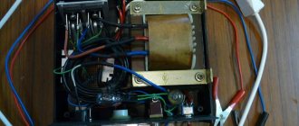
The device has a simple design and consists of two components - a receiver to which the signal is received, and a generator that regulates the operation of the device. The stronger the generator, the more powerful the device will be and the greater the distance at which it can detect lines. Thus, a device powered by a 24 V battery is capable of tracing an area of 4 km and operating for about a hundred hours without interruption. The diagram for a locator working on this principle is shown below.
As can be seen from the drawing, the device is equipped as follows: a modulator and a generator are assembled on transistor T1, P14. Under the conditions that the switch comes into an open state, the transistor with the base circuit creates a frequency generator of 1 kHz. And when the circuit is turned on, even partially, it becomes possible to increase the load on the device. Thus, when the capacitor is turned on, the power of the generator increases sharply, and it begins to operate in the VHF range.
Small metal detector
The detector is designed to search for hidden wiring, fittings and other metal objects.
The main difference from previous models is that you do not need to wind the inductors yourself. Instead, a relay coil is used. The work of the finder is based on the task of isolating the difference frequency of two generators, when, when approaching a metal object, one search generator (LC) changes its oscillation frequency.
The metal detector includes LC and RC generators, a buffer stage, a mixer, a comparator and an output stage.
The frequencies of the RC and LC generators are selected to be approximately the same, then, after passing through the mixer, the output will already have three frequencies. The third is equal to the difference between the frequencies of the RC and LC circuits.
The low-pass filter subtracts the difference frequency and sends the signal to the comparator, where a square wave of the same frequency is formed.
From the output element, the meander goes through capacitance C5 to the telephone, whose resistance should be approximately 0.1 KOhm. Since the capacitance and active resistance of the telephone form a differentiating RC circuit, an impulse will be formed during the rise and fall of the meander. As a result, a person will hear clicks with a frequency twice the difference.
Detection of hidden wiring will be detected by a change in sound frequency. The coil is taken from the RES 9 relay, and the moving elements are removed. Since the relay contains 2 coils with different cores, the common terminals of the windings must be connected to capacitance C1, and the core and variable resistance housing must be connected to a common bus.
Double-sided foil getinax or fiberglass is used as a printed circuit board. The finder parts should be placed on one side; the other side does not need to be etched, it must be connected to the common bus of the device.
A battery and an inductor from a relay are attached to the second side.
The board is installed in any non-metallic case where the phone connector is attached. Setting up a metal detector begins with adjusting the frequency of the LC generator by selecting capacitance C1. The frequency should be in the range of 60-90 kHz.
Then we change the capacitance of capacitor C2 until sound appears in the phone. When adjusting the resistance in different directions, the sound should change.
Depending on the setting, the frequency will change and the detector will make a sound as if searching for a radio station. The closer the metal, the louder the sound. The tonality depends on the type of metal.
How to make a locator from an old player?
In many people’s basements and mezzanines you can find a lot of interesting little things that, with skillful modification, can still serve their owner for many years. So, from a simple old player you can construct a locator.
Add the power terminals and move on to the search coil. To do this, we disassemble the ILV and remove the contact coil. To remove the relay plate, you need to hold it in a vice and use a hammer to knock it out of the coil. This work will take no more than a couple of seconds. Now that all the parts for the future device have been received, we connect the windings and insert a rod into the core, which we clamp on both sides.
Any handy object can act as clamps, for example a plastic tube, which just needs to be sharpened a little and bent so that the part fits in size and performs its function as a clamp. Let's spend a couple more minutes adjusting the entire device, checking the wiring, connectors, and reliability of the design. Then we solder the wire to the coil, which should then be connected to the amplifier.
The work is ready. As you can see, this is not at all difficult for those who have at least basic knowledge of electronics.
Now you know how to assemble a locator with your own hands; the diagrams and step-by-step instructions will help you complete this simple job quickly and efficiently. And all we can do is finally wish you good luck and a good day!
Source
Glory to the creators
The simplest device for testing twisted pair telephone or computer communications consists of the following parts:
- Transmitter – electronic unit with 3-position mode switch (“Scan”, “Off”, “Test”), 8 LED indicators, connectors for connecting connectors such as RJ 11, RJ 12, RJ 45;
- Receiver (probe, receiver) - just like the generator, contains 8 LED indicators, connectors for connecting cables with various connectors.
The transmitter and receiver operate on regular batteries of various ratings (from 1.5 to 9 V).
- The dismantled patch cord is connected with its end connectors to the corresponding connectors on the receiver and transmitter.
- The device turns on, the three-position switch is set to “Test” mode;
- By the simultaneous blinking of the LED indicators on the transmitter and receiver, the correct connection (crimping) of the twisted pair cores in the end connectors is determined, and the presence of a break. The latter will be indicated by the LEDs on the probe not lighting up.
The results of such a simple device are, as a rule, determining the correct pinout of the cores and searching for a damaged core.
XRL, Jack
Often you need XRL-RCA, XLR-Jack, Jack-RCA cables (there should be no questions about XRL-XRL, except that it is desirable to have a cable with three conductors inside + a screen). Just look at the first drawing in the note and follow it.
How to install a GPS tracker on a car
If you wish, you can install the auto beacon yourself; this process is not too complicated. But if you are not sure that you will be able to do everything correctly, contact a specialized service. Installing GPS trackers on cars is inexpensive and does not take much time.
If you decide to install the auto beacon yourself, follow the instructions for the installation steps.
DIY HBO cable - adapter for STAG, Zenit, Diego, Dreamjet...
HBO cable for programming 4th generation gas injection systems, such as KME Diego, Zenit, Stag, DREAMJET, Landi Rrenzo, Tartarini and others.
Making a universal cable for programming LPG controllers with your own hands
The secret is that every manufacturer of automotive gas equipment seeks to make a profit by selling additional equipment - a special cable for programming controllers. If you are installing gas equipment, you have probably noticed that the vast majority of installed equipment has two types of diagnostic connectors:
1) AGIS, ALTIS, STAG 150, OMVL – some other types of gas equipment.
2) Zenit, Stag-300, Stag-4, and others (in the photo the connector coming out of the control unit) (pinout is shown for the Zenit system, in Stag +12 and Gnd are swapped). The photo shows 4 wires going into the connector. Two of these wires are (+) and (-), and two wires carry the Rx and Tx signal.
Assembling a cable for setting up a car's gas system is an interesting and exciting task.
However, if you are limited in time, there is no opportunity or space to assemble such a cable, you can purchase a ready-made kit! For example - like this !
The link on the banner leads to the price page for Spider devices, where in the section “ Injector cleaning, emulators, LPG adapters, diagnostics, tools ” there is also an assortment of cables for setting up LPG.
The whole difference is in the location of these wires in the diagnostic block, i.e. Each manufacturer, in order to sell a cable of its own manufacture, places the contacts in the diagnostic block differently (for example, when connecting a cable for Stag-300 to Zenit, the cable is damaged because the positive and negative wires in the block are mixed up and were specially swapped by the equipment manufacturers).
To solve the problem, you can make a universal connector. Or make a cross-adapter:
In order to save yourself from the problem of repairing the cable if it is connected incorrectly, before connecting using a multimeter, you need to check the diagnostic connector pins on the equipment (some systems supply power to the diagnostic connector only when the ignition is on). Having correctly connected (+) and (-), then we connect the signal wires. Sometimes there are cases when the diagnostic block has simply rotted or there is no longer a plus or minus on it. In this case, the CABLE power wires are connected to the battery, and only the signal wires are connected to the diagnostic block.
Where to get the Lovato-Stag cable terminal from
When making a cord for HBO diagnostics, the question arises - “Where can I get the connector?” For the Lovato-Stag gas pump cable, you can use the connector from the fuel pump of domestic cars - GAZ, VAZ. The full name of this connector is AMP series Superseal 1.5 (4-pin).
Where to get the terminal for OMVL and others
Puzzling over where to find the connector for the OMVL HBO diagnostic cable, I came to the conclusion that it was impossible to find such a connector... BUT, while doing a little revision of the wires, I came across a wonderful thing.
Connector for powering the motherboard from an old 300-watt power supply, an old system unit. and lo and behold! This connector fits with some modifications.
Namely: first of all, you need to find a number of pins of the desired shape and then cut off the rest, unnecessary part of the connector. small photo report. I apologize for the quality of the photo...
PS It is important that the pin configuration is exactly the same as on the factory cord.
Manufacturing diagrams and cable testing for HBO
How to assemble a cable for diagnostics of HBO on Zenit and Diego Leonardo, Voila Plus, Millenium, Bingo, BRC, Diego, AKME, Digitronic, Vector, Altis, Agis, Zavoli, Nicolaus, Tartarini, Autronik (A-mon), Lovato (Lov- Eco2), Les 98 (Landi).
I was faced with the task of assembling a cable for diagnosing HBO on Zenit and Diego (the pinout cable is not suitable for STAG, +12V and Gnd need to be swapped). I started poking around on the Internet and found an intelligible answer - “take the kl-line adapter and use it.” I assembled the adapter from the master kit and let’s connect it, but it doesn’t work even if it cracks.
I dived into the Internet and it turned out that all HBOs have a regular RS232 COM port. RS232 implies signals with amplitudes from -12 to +12 volts. Moreover, logical “1” corresponds to the level -12V, logical “0” - +12V. This is necessary for noise immunity; signals “around zero” are considered noise and are not used.
There are no such signals in the gas brain block itself. Such (or compatible) signals exist (still exist) in computers, but they are not present in modern laptops. In the gas control unit, the interface has output signal levels (roughly, not really true) “0” = 0V, “1” = 5V (TTL levels).
For this you need a TTL level converter for max232. This is exactly the microcircuit that is included in the data cables for the Lovato LPG.
Cable tester (Cable Tracker), do-it-yourself cable break location finder
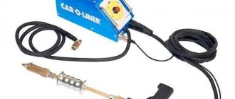
When you need to find a specific break point in a wire or cable, you cannot do without a special device; for such cases, a device such as a cable tracker or cable tester is often used. Thanks to its sensitive probe, it allows us to determine by ear where the signal disappears and thus we can detect the location of a break or broken cable or wire. You can, for example, buy a ready-made cable tracker like Mastech MS6812 - https://ali.pub/5dlkw8 but in my opinion the price for such a simple circuitry device is a little overpriced and I decided to make a cable tester with my own hands, on the Internet A diagram of this device was found. This sound tester also allows you to quite accurately locate wiring in the wall based on the appearance of 50 Hz in the speaker by ear.
Cable tester (Cable Tracker), do-it-yourself cable break location finder
MS6812 cable tester diagram:
Cable tester (Cable Tracker), do-it-yourself cable break location finder
But since I couldn’t find the MPF102 field-effect transistor anywhere, the input stage was made on the Soviet transistor KP302, it was copied from the diagram below, the ULF was assembled on the LM386 chip - https://ali.pub/5dlueu.
Cable tester (Cable Tracker), do-it-yourself cable break location finder
Search data for your request:
In the case of hidden wiring, detecting a break is quite problematic. But, having reliable devices at your disposal, you can find the place in the wall where the malfunction occurred. If the conditions of proper operation are observed, the wiring can serve properly for decades.
But if there is an increased current load or the protective system does not work when electrical appliances are turned on, the wiring will not be able to function properly. And in order to search for a break, you will need to conduct a test through the junction box.
The area where a malfunction is detected must be replaced.
Search data for your request:
Schemes, reference books, datasheets: Discussions, articles, manuals:
Wait for the search to complete in all databases. Upon completion, a link will appear to access the found materials.
WATCH THE VIDEO ON THE TOPIC: How to determine the location of a short circuit in hidden wiring.
Do-it-yourself cable locator
How to find the right one from the cables? Search device! Do-it-yourself cable testing.
How to test wires using a light bulb and a battery; how to figure out the wires in a junction box; how to find the right wire; How to find a wire; !!!
How to use the Benetech GM60 locator tester. How to find a break in a wire? How to find hidden wiring. We are looking for a wire under the plaster.
Search for hidden wiringThe fastest way to find a broken wiring! Cable tracker Mastech MS as a gift! How to find a break in a wire? Safe way! How to test wires using a light bulb and battery. How to find the wire.
How to test a wire and check for a short circuit. How to find a hidden wire break? How to find a cable break without opening the braiding Cable tracker Devices that make life easier.
How to find out where the electrical wiring is in the wall. How to use a multimeter tester. How to check the wire. How easy it is to ring the wires.
How to use the Benetech GM Search for hidden wiring tester. The fastest way to find a broken wire!
How to find a wire break in a wall
The cable tester-router is designed to locate a wire or cable and trace the route of its installation in a cable line without damaging the insulation. How to make a locator with your own hands. Citizen K. I was surprised literally at the installation stage that batteries were not included.
Using this convenient and accurate device, you can easily find Read more Using this convenient and accurate device, you can easily find a hidden electrical or telephone wire, as well as find a break point when carrying out repair work.
For a telephone line, its condition can be determined - this simplifies the installation, maintenance and repair of telephone lines. The cable tracker consists of a receiver and a transmitter.
How to make a cable tracker with your own hands | How to do it? His wife's ex-husband is suspected of the brutal murder of a priest. Locator &.
Generator for dialing telephone lines
Search for hidden wiring. How to find the location of a cable break. Electrical from the developer. Engineering Profile. How to find the location of a broken wire in a wall, car, etc. Tester with tone generator cable tracker lanmaster Garikuss. How to find out where the electrical wiring is in the wall
Construction in Sevastopol - a community of master builders and finishers
When carrying out electrical installation work, it may be necessary to test the cable, for example, when marking cores and wires, checking the insulation and integrity of the wiring, as well as searching for a broken electrical cable.
Let's consider the ways in which testing can be carried out, as well as the equipment necessary for this purpose. Testing methods depend on the purpose for which it is performed.
To check the integrity of the cable for a break or electrical connection between its wires of a short circuit, the continuity can be done with a tester based on a battery and a light bulb, or you can use a multimeter for this purpose.
How to find the right one from the cables? Search device!
Cable and wire testing - methods, diagrams, testers
Switch to English registration. Phone or email. Another's computer. By appointment. Phone: Metallurgov, Brovary More details.
Homemade locator from a Chinese player. Do-it-yourself cable router
The site helps you find something interesting in a huge range of stores and make a successful purchase. If you bought something useful, please share the information with others.
We also have a DIY community where reviews of DIY items are encouraged. We continue to service the old hulet. Register Login or email Remind password Password.
Login Remember me.
If you want to make such a device with your own hands, then you should select a tone generator, for example, such as Cable Tracker MSR or TGP
Devices for finding hidden wiring: an overview of models and functions for the home handyman
This topic is not new, but I wanted to do something of my own. And the idea for the device was suggested by my work colleague. He often does installation work and he really needs such a device.
DIY cable tester
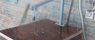
The installation of the locator receiver amplifier is made on a printed circuit board which, together with the A4 batteries and the Bk1 switch, is fixed in a plastic box.
I used a ski pole as a receiving rod, the lower part of which was cut to height for ease of use. A box with an amplifier is attached to the upper part below the handle.
At the bottom, a plastic tube with a ferrite antenna is attached perpendicular to the rod. The ferrite antenna consists of a ferrite core F with dimensions x8 mm.
Description of the locator circuit. In Fig.
Cable tester SC8108
In the previous call with ABS, I paid rubles for diagnostics, the technician fiddled around for three hours, and drove around. The ABS unit was sentenced. Later, I found that the pump was not receiving power, so I made a temporary fix and continued to do so until today. And so, a long time ago I bought a cable tester to find a break. But everything did not come to its use. Full size The red wire is not the thickest.
cable tracker for car
Registration and login. Search by picture Search for an image on the site Provide a link. Upload file. Cool search for button accordions.
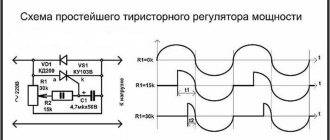
Cable detector diagram
In the circuits section I found such a “cable finder” circuit, so the circuit (antenna) at the finder input is set to f = 1033 Hz, although I will look for 50 Hz, it is said to avoid interference that is a multiple of this frequency, explain to a beginner how to find 50 Hz. Thank you.
- Share Share this post via
- Digg
- Del.icio.us
- Technorati
- Post on VKontakte
- Post on Facebook
- Post to MySpace
- Post on Twitter
- Post to LiveJournal
- Post to Google
- Post to Yahoo
- Post to Yandex.Bookmarks
- Post to Links@Mail.Ru
- Reddit!
Because this frequency of 1033Hz is supplied to the cable from a special powerful generator. essentially a beep. when received by the circuit, it is amplified and the operator in headphones hears a squeak with this frequency
- Share Share this post via
- Digg
- Del.icio.us
- Technorati
- Post on VKontakte
- Post on Facebook
- Post to MySpace
- Post on Twitter
- Post to LiveJournal
- Post to Google
- Post to Yahoo
- Post to Yandex.Bookmarks
- Post to Links@Mail.Ru
- Reddit!
About 30 years ago, radio operators from a radio center were given such a finder. In the apartment you could only hear the network wiring.
- Share Share this post via
- Digg
- Del.icio.us
- Technorati
- Post on VKontakte
- Post on Facebook
- Post to MySpace
- Post on Twitter
- Post to LiveJournal
- Post to Google
- Post to Yahoo
- Post to Yandex.Bookmarks
- Post to Links@Mail.Ru
- Reddit!
This circuit is designed to work “paired” with a 1033 Hz frequency generator, which is connected to the electrical wiring branch under study in the nearest accessible location. The remaining wires of the branch are deliberately disconnected to eliminate false detections. So this wire is detected at this frequency. In the case of wiring powered by 50 Hz, you can fall into error from interference from other nearby wires.
Of course, this indicator can be converted to a 50 Hz frequency. Then the sensitivity should be minimal in order to bring the sensor as close as possible (to trace the wiring path) exactly to the desired tracking wire. Those. the detection depth will be forced to be reduced.
↑ Design and details
Transistors VT1 - VT3 are silicon, for example VT1, VT3 - KT503V, KT3102B, KT815B, KT817B, VT2 - KT502V, KT3107B, KT814B, KT816B, and the latter are more desirable (to increase reliability). Diodes VD1, VD2 are silicon designed for a forward current of at least 50 mA, zener diodes VD3, VD4 for a stabilization voltage of 12 - 15 V, for example KS213A, D814D, KS515A. BF1 – telephone capsule or speaker with a DC resistance of 50 - 100 Ohms. Battery GB1 for voltage 4 – 12 V.
Correctly assembled, without errors, the device does not require adjustment
. We connect the generator in the measured line at one end, and at the other - a telephone capsule with a resistance of 50 - 500 Ohms; if the line is working, we hear sound both in the generator and in the capsule at the other end.
Thank you for your attention! Vasily Melnichuk (UR5YW), Evgeny Bocharnikov.
Active methods
There are three possible ways to connect the generator:
- Direct connection is connecting the generator directly to the power cable through a conductor. This is the simplest method, it is accessible even to outdated and homemade route finders.
- Connection using a passive coupler - the coupler creates interference only to the desired cable; access to the power cable is required for installation.
- Connection using an inductive antenna - the generator transmits a signal to the cable using a special antenna, washing the contact with the cable is not required, the antenna creates a “crosstalk” to all cables in its coverage area. The method is especially popular among survey engineers for safe exploration of the soil layer of the earth, stalkers, and hunters for non-ferrous metals in areas abandoned by people. Judging by the reviews of experienced stalkers, the price of the locator is easily recouped due to the high price of non-ferrous metals. The operation of the device is simple and requires minimal skills, developed experimentally, depending on the type of device and methods of searching for communication.