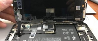
Most laptops are equipped with modern video cards. Computer manufacturers are creating GPU adapters using new technology. A design feature of such components is the absence of microcircuit legs, which were used previously. Instead, a grid of balls is stretched on the surface of the video chip. They perform the functions of microcircuit contacts.
Security Methods
Ventilation: Flux fumes from soldering and desoldering can be harmful. Use general or local exhaust hoods to comply with the Maximum Permissible Concentration of Harmful Substances in the workplace. Consult the technical data sheet (MSDS) for soldering materials for permissible maximum concentration limits.
Personal Protection: Chemicals used in the reballing process may cause damage to areas of the skin. Use appropriate safety equipment when performing cleaning, soldering or desoldering activities
Lead Hazards: The USEPA Carcinogen Assessment Group classifies lead and its alloys as teratogens and its components as a Class B-2 carcinogen.
When working with static-sensitive components, ensure that your work area is static-free by using the following:
- Fingertips
- Conductive work mat or table cover
- Grounded heel or wrist bracelets
Soldering for Beginners
A novice electronics repairman has a huge number of questions. Having been engaged in soldering work, both SMD components and BGA microcircuits, for more than 8 years, Bgacenter experts have prepared for you a comprehensive soldering guide. You can also learn soldering for beginners under the guidance of experts, here is a professional soldering program.
Susceptibility of components
Sensitivity to Humidity Plastic BGA packages are moisture absorbent.
The chip manufacturer designates the component's sensitivity level on each package. Each level of susceptibility has a time limit for external influence associated with it. The JEDEC standard reflects the time limit for external exposure at standard atmospheric pressure, 30 degrees C and 60% relative humidity. Our instructions also provide a table of humidity levels (see information below). If the permitted exposure time is exceeded, the JEDEC standard requires drying of the component. The standard drying time is 24 hours at 125 degrees C. After drying, the component should be placed in a bag with a moisture-absorbing substance, which will prevent moisture from re-entering it. This drying will prepare the component for the soldering process. Susceptibility to Static Charge The sequence of removing, reballing, and reinstalling a component on a PCB creates multiple chances of static charge damaging the component. Try to use appropriate protective equipment. If the allowed exposure time is exceeded, the JEDEC standard requires drying of the component. The standard drying time is 24 hours at 125 degrees C. After drying, the component should be placed in a bag with a moisture-absorbing substance, which will prevent moisture from re-entering it. This drying will prepare the component for the soldering process.
Temperature Sensitivity BGA components are susceptible to temperature changes in the following cases:
- Rapid changes in temperature will lead to thermal shock due to uneven distribution of internal temperatures within the chip itself. Rapid heating of just one side of a BGA chip can cause thermal shock to the chip substrate.
- Elevated temperature: Plastic BGA chips are most similar to printed circuit boards. Their substrates consist of tempered glass and typically have a Tg (glass transition temperature) of approximately 230 degrees C. Above the glass transition temperature, the coefficient of thermal expansion begins to increase, adversely affecting internal temperature shocks. It is very important to keep the chip substrate below this temperature.
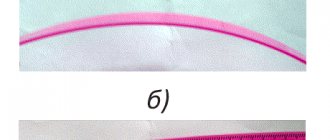
- Uneven temperature heating: It is recommended to use a convection type oven rather than a gun type soldering system. Effective soldering of components requires a furnace that provides uniform heating of the components. Moreover, a furnace that is capable of delivering hot air at a low velocity can reduce the likelihood of thermal shock due to uneven heating of the component. The layer of ball leads helps to isolate the substrate contact pads from air. The "soak" time in the oven gives time for all pads to be evenly wetted with solder. When the temperature profile reflow process is complete, the ball leads are light brown in color. High blowing temperatures can cause the terminals to appear dark brown or even black.
- It is recommended that BGA components never exceed 220 degrees C.
Susceptibility to shock. Internal shocks occur due to thermal gradients and stresses within the chip structure. Thermal shocks are more noticeable during the reballing process, even when both types of shocks are present. To minimize the risk of temperature shock, carefully monitor the process temperature cycle. Heating uniformity is critical to minimizing shock to the chip.
Video card diagnostics
Diagnostics of the video card was carried out in the following sequence:
- We checked the installation of the video driver in the test bench (before starting the VK test under load). To do this, go to computer properties, then to Device Manager. Then open the video adapter branch and make sure that the video card is correctly identified.
- We launched a load - Furmark, GPU-Z or a YouTube video with FullHD resolution. Please pay attention to the appearance of artifacts. If artifacts appear, the video chip or graphics memory is most likely faulty.
- We launched the MATS utility to check video memory channels. Test result: If the test passes, then the memory is working.
- When there are errors on all memory channels, it means the memory controller in the chip itself is faulty. Rarely, a GPU reball can help.
- If the error is in one memory channel, then the microcircuit is faulty and needs to be replaced.
- If there are no block errors, the chip is most likely faulty. It needs to be replaced.
- In our case, there were no errors in MATS. The decision was made to replace the GPU.
- We disassembled the video card. We removed the cooling system and backplate (if equipped). Pay attention to the cooler and backlight cables (if available).
- Removed the thermal paste from the video chip. For this we use a dry cloth. If you use alcohol or other liquids, the thermal paste will spread all over the video card and turn it pale white. Be careful when removing thermal paste from capacitors around the GPU.
- If there are thermal pads, pay attention to their condition. Possible options if:
- They break when removed (fragile) and need to be replaced.
- Thermal pads are “non-greasy” and do not leave greasy marks on your hands, which means their service life is coming to an end and it is advisable to replace them.
- We examined the video chip. Emphasize on:
- Chip end color. If the PCB is dark brown, most likely it was soldered. That is, the video card was repaired. There are chances that the chip was soldered poorly, in which case it will be enough to remove the video chip.
- The color of the compound around the crystal. If the compound is darkened, the chip may be damaged as a result of improper maintenance of the cooling system
- Presence of crystal damage. Inspect for cracks or chipped edges and corners.
Comparison of the color of the compound around the crystal
The process of removing ball leads (deballing)
There are many tools that allow you to remove solder residue from a BGA component.
These include hot air vacuum tools, tip soldering irons and, most preferably, low temperature wave soldering machines (220 degrees C.) Any of these tools, when used correctly, allow for reballing. Since soldering irons with good temperature control for soldering are not so rare these days and are relatively inexpensive, we will describe the deballing process using a soldering iron with a tip. Stay confident throughout the deballing process because... it contains many mechanical and thermal stresses that are potentially harmful to the chip. Tools and materials
- Flux
- Soldering iron
- Isopropyl wipes (isopropyl alcohol)
- Conductive mat
Additional recommended tools
- Microscope
- Exhaust hood to facilitate the removal of fumes generated during the desoldering process
- Protective glasses
- Scissors
Preparation
- Preheat the soldering iron
- Put on finger pads
- Pre-check each chip for contamination, missing pads, and solderability.
- Wear safety glasses
Note:
It is recommended to dry the component to remove moisture before deballing it.
Step 1 - Apply Flux to the Chip
Place the chip on a conductive mat, pad side up. Too little flux will make the deballing process difficult.
| Fig.3 Scratched pads of the BGA chip | Step 2 - Removing the Balls Using a desoldering wire and a soldering iron, remove the solder balls from the chip's pads. Place the braid on top of the flux, and then heat it with a soldering iron from above. Before moving the braid along the surface of the chip, wait until the soldering iron warms it up and melts the solder balls. ATTENTION: Do not press on the chip with a soldering iron. Excessive pressure may damage the chip or scratch the pads. (see Fig.3) For best results, clean the ip using a clean piece of braid. A small amount of solder should remain on the pads to make reballing easier. |
| Step 3 - Cleaning the Chip Immediately clean the chip using a cloth soaked in isopropyl alcohol. Timely cleaning of the chip will make it easier to remove flux residues. Remove the napkin from the bag and unfold it. By wiping the surface of the chip, remove the flux from it. Gradually move the chip while wiping to cleaner areas of the napkin. Always support the opposite side of the chip when cleaning. Do not bend the corners of the chip. Note: 1. Never clean the BGA chip with a dirty area of the tissue. 2. Always use a new wipe for each new chip. | |
| Fig.4 Clean BGA surface Rice. 5 Dirty BGA surface | Step 4 - Inspection It is recommended that inspection be carried out under a microscope. Check for clean pads, damaged pads, and loose solder balls. (See Figures 4 and 5) Note: Since the flux is corrosive, additional cleaning is recommended if the chip is not reballed immediately. |
| Step 5 - Additional Cleaning Apply deionized water to the chip pads and scrub them with a brush (you can use a regular toothbrush). Note: For best results, brush the chip in one direction first, then rotate it 90 degrees and brush in the other direction. Then clean using circular movements. | |
| Step 6 - Rinse Give the chip a good brush and rinse with deionized water. This will help remove any remaining flux from the chip. Then dry the chip with dry air. Recheck the surface (Step 4). If the chip will lie for some time without the applied balls, you need to make sure. That its surface is very clean. Immersing the chip in water for any length of time is NOT RECOMMENDED. |
Signs of a video chip malfunction
The need to reball the video chip manifests itself in the form of characteristic symptoms:
- no response to pressing the power button;
- black screen;
- random reboots;
- the image freezes in one position;
- interference, picture distortion, “artifacts”;
- incorrect color rendering;
- the image is divided into several parts.
Each of these signs indicates a video card malfunction. The component stops working due to constant voltage surges, the laptop being flooded with liquid, or mechanical damage.
If the GPU module of your laptop is presented in the form of a separate chip, which is connected to the MXM or MXM II connector (external video cards), then you can safely replace the broken part. It is much more difficult to restore a laptop with an integrated video card. Many users and workshops are trying to save money on equipment repairs, so instead of completely replacing the component, they carry out reballing, that is, warming up the chip.
The process of applying ball leads (reballing)
Tools and materials
- Repair stencil
- Stencil clamp
- Flux
- Deionized water
- Cleaning tray
- Cleaning brush
- Tweezers
- Acid-resistant brush
- Reflow Oven or Hot Air Soldering System
Additional recommended tools
- Microscope
- Fingertips
Preparation
- Before you begin, make sure the stencil holder is clean
- Set the temperature profile for the solder reflow equipment.
| Step 1 - Inserting the Stencil Place the stencil in the holder. Make sure the stencil is hung tightly. If the stencil is bent or dented in the clamp, the restoration process will not work. This is usually a consequence of contamination of the clamp or poor adjustment of it to the stencil. | |
| Step 2 - Apply Flux to the Chip Use a syringe to apply a small amount of flux to the chip. Note: Please make sure before you start. that the chip surface is clean. | |
| Step 3 - Distributing flux over the surface of the chip Using a brush, spread the flux evenly along the side of the contact pads of the BGA chip. Try to coat each pad with a thin layer of flux. Make sure all pads are coated with flux. A thinner layer of flux works better than a thicker layer. | |
| Step 4 - Inserting the Chip Place the BGA component into the fixture, with the flux-coated side facing the stencil. | |
| Step 5 - Securing the Component Seal the stencil and component into the fixture by gently pressing down on the component. Make sure the component sits flat against the stencil. | |
| Step 6 - Reflow Place the fixative in a hot convection oven or hot air reballing station and start and run the reflow cycle. In any case, the equipment used must be configured to the thermal profile developed for the BGA chip. | |
| Step 7 - Cooling Using tweezers, remove the retainer from the oven or reballing station and place it in the conductive tray. Leave the chip to cool for about a couple of minutes before removing it from the retainer. | |
| Step 8 - Removing the BGA Chip Once the chip has cooled, remove it from the retainer and place it in the cleaning tray, ball side up. | |
| Step 9 - Soak Apply deionized water to the BGA stencil and wait about thirty seconds before continuing. | |
| Step 10 - Removing the Stencil Using fine tweezers, remove the stencil from the chip. It is best to start from a corner, gradually removing the stencil. The stencil must be removed in one go. If it doesn't come off, add more deionized water and wait another 15 to 30 seconds before continuing. | |
| Step 11 - Cleaning Up Any Dirt Fragments There may be some small bits of particles or dirt remaining after removing the stencil. Remove them with tweezers. Just gently move one tip of the tweezers between the balls of the component, grabbing the particles with the other. WARNING: The tip of the tweezers is sharp and may scratch the solder mask on the chip if you are not careful. | |
| Step 12 - Cleaning Immediately after removing the stencil from the chip, clean the egeo using deionized water. Apply a small amount of deionized water and scrub the chip with a brush. CAUTION: Support the chip while brushing to avoid mechanical stress. Note: For best cleaning results, first scrub the brush in one direction, then turn it 90 degrees and scrub in the other direction. Complete the cleaning process with circular movements of the brush. | |
| Step 13 - Wash the BGA Chip Wash the chip with deionized water. This will help remove small particles of flux and dirt left behind from previous cleaning steps. Let the chip air dry. Do not wipe it with napkins or cloths. | |
| Fig. 6 Clean BGA balls Fig. 7. Corroded residues at the base of the balls | Step 14 - Check Application Quality Use a microscope to check the chip for contamination, missing beads, or flux residue. If re-cleaning is necessary, repeat steps 11 - 13. CAUTION: Since the process does not use clean flux, careful cleaning is necessary to prevent corrosion and further chip failure. Note: Steps 9 - 13 are unambiguous. At some other stages it is also possible to use spray cleaning. |
Cleaning the Retainer
| During the BGA reballing process, the fixative becomes increasingly sticky and dirty. Rice. 10 shows traces of contamination on the fastener. It is necessary to clean the remaining flux from the clamp so that the stencil fits correctly. The process described below applies to both flexible and rigid fasteners. For better cleaning, it’s a good idea to use an ultrasonic cleaning bath Tools and materials
Additional recommended tool
|
| Step 1 - Soak Soak the BGA stencil fixative in warm deionized water for approximately 15 minutes. |
| Step 2 - Cleaning with Deionized Water Remove the retainer from the water and scrub it with a brush. |
| Step 3 - Rinse the Retainer Rinse the retainer with deionized water. Let it air dry. |
Chip drying
The drying procedure is very important to ensure that there is no popcorn effect during the chip reballing process.
It is highly recommended to dry the chip before each reballing operation to prevent the presence of moisture for a further period of time. Additional recommended tools
- Drying oven
- Package protecting against humidity and static charge
- Desiccant agent (for example silica gel)
Preparation
- Pre-check each chip for contamination, missing contact pads, and the possibility of soldering.
- Prepare and clean your work area.
Step 1 - Chip Humidity Level
Select the desired chip humidity level from the table below to determine the time required to dry the BGA component. The BGA manufacturer is required to indicate the level of sensitivity of the chip to humidity. You also need to know the amount of time your chips are exposed to the environment. If the exposure time exceeds the chip's sensitivity level by 2-5 times, a 24-hour drying period at 125 degrees C is required . (Note: If you are unsure about the exposure time of the chips to the external atmosphere, it is better to assume that it has been exceeded.)
Additional information regarding the humidity/reflow temperature susceptibility level of surface mount components can be found in IPC/JEDEC J-STD 033A.
ATTENTION:
Never dry BGA components in plastic trays made from a material with a melting point less than 135 degrees C. Moreover, do not use trays that are not clearly marked with their maximum operating temperature. Do not allow the solder balls to touch metal surfaces during the drying process.
Step 2 - Drying
Set the oven temperature and time according to the humidity level. When the oven reaches the required temperature, place the BGA components in it.
Step 3 - Dry Packing
Once drying is complete, place the components in a static-protected moisture-proof bag with a fresh dose of desiccant. A desiccant will help you keep components dry during storage and transportation.
Is it worth reballing a laptop video chip?
Today this is a common service provided by service centers; many users warm up the chip at home. However, how effective is it? Is this type of equipment restoration justified? Reducing the cost of repairs is an attempt to extend the service life of the component. Therefore, you need to carry out a full reballing or replace the broken part.
Text kindly provided by a specialist from the Odessa-Repair service center
Subscribe to us on Google News, and also read us on Telegram and Facebook
Moisture Susceptibility Level Chart
| Susceptibility level | Exposure time (outside the protective bag) at 30 degrees C/60% relative humidity or as expected |
| 1 | Unlimited when |
| 2 | 1 year |
| 2a | 4 weeks |
| 3 | 168 hours/td> |
| 4 | 72 hours/td> |
| 5 | 48 hours/td> |
| 5a | 24 hours/td> |
| 6 | Forced drying before installation. After drying, it must be installed within the time indicated on it. |
Reflow Temperature Profile
As with all soldering processes, the temperature profile is a key element to a successful process.
The process of reballing a BGA chip itself is quite simple and repeatable; setting up the temperature profile for hot air reflow equipment takes much more time. Each BGA chip may require a different temperature profile. Start with the basic profile shown below, making adjustments for BGA material type, BGA chip weight and size should yield acceptable results. Please note that the profile setting is based on the measured component temperature. The temperature in the oven itself is usually different from it. ATTENTION:
Do not heat the component above 220 degrees C, as... this may cause it to fail.
Recommended reflow equipment:
Any hot air equipment equipped with:
- Time-controlled heating cycle
- Heating temperature range 20 - 240 degrees C
- Circulating air blowing
Key points:
- The slope of the temperature curve (temperature rise) is about 1 degree C/second
- The temperature peak should be between 200C and 210C
- Presence of liquidus line (183C) at 45-75 seconds
- Larger components or heat sinks will require longer heating cycles
Measuring Component Temperature
To create a working temperature profile, thermocouples are placed in various areas of the component, and their readings are monitored using special software, which allows you to find the optimal reflow profile of the component.
This reading method ensures uniform heating readings and minimal thermal shock to the component being tested. Adjusting the Airflow for Reflow
The equipment used for reflow will dictate how the retainer should be installed in it. Ensure that the clamp is installed so that the circulating air flow reaches the bottom of the chip or stencil. Do not place the clamp on the surface as shown in Fig.12
Fig. 12 INCORRECT placement of the clamp during reflow
Figure 13 shows the CORRECT way to heat a component. Most ovens have special guides that allow air to flow freely over the component. Hot air tools used to remove a component from the surface of a printed circuit board will not hold the retainer. The most preferred equipment is one in which the retainer is retained from both the top and bottom surfaces. These types of equipment may provide spacers or washers under the retainer to allow hot air to flow under the retainer.
The air flow around the component causes it to heat up. When a component is heated unevenly, temperature gradients (temperature changes) occur in its composition. A large temperature gradient results in thermal shock, which can damage the component.
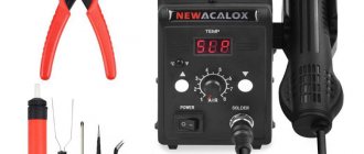
Soldering Station
We will talk about choosing a specific model in other publications, but in this article let’s decide on the type of soldering station.
For successful installation/disassembly of a small BGA chip, such as a mobile phone, a Lukey 852D+ hot air soldering station is sufficient. A more convenient option is a portable infrared soldering station like Tornado Infra Pro.
| Lukey 852D+ | Tornado Infra Pro |
If you need to restore a laptop motherboard with a large PCB area and large BGA chips, then, in this case, you cannot do without a repair complex with a lower and upper heater such as Jovy Systems RE-8500. You can read more about choosing a soldering station in the corresponding article.
| Jovy Systems RE-8500 |
FAQ
Q - How do I know if a component is clean enough?
A - The best way to tell if a component is clean enough is to use an ionograph or other similar equipment to detect ionic contaminants.
Q - What should the lead balls look like after the reballing process?
A - After reflow, the balls on the BGA component should be spherical and smooth. Their surface structure, like the skin of an orange, indicates that the reflow time is too long, the reflow temperature is too hot, or the cooling process is too slow.
Q - The stencil sticks to the component during its removal. What can I do?
A - Apply more water and let the stencil soak for a longer time. This usually helps. Increasing the water temperature can also have a positive effect. When this problem occurs, it usually means that the reflow cycle is too hot or too long.
B - One of the balls did not stick to the contact pad. What can I do?
A - The use of flux and temperature profiling is often the cause of these ball contact problems. Apply a small amount of flux to the pad and place a separate ball of flux on it, then melt it. This will allow you to secure the ball that was not soldered the first time. If there are too many of these balls, deball the chip and repeat the process of applying ball pins.
B — After several cycles of use, the stencils no longer adhere clearly to the clamp. What can be wrong
A - Flux can build up on the inside of the fastener and cause problems with fixing the stencil.
Clean the retainer according to the instructions above. Stencils \ Technical information >>>
Flux for BGA
| Interflux IF 8300-6 | Interflux IF 8300-4 |
One of the key factors for successful reballing is the correct flux. It is its properties that determine how the balls “stick” to the chip before heating, whether it will boil and foam during heating, and whether it will need to be washed off after mounting the chip on the board.
Therefore, BGA flux is the highest quality and most expensive type of flux. The use of other fluxes is extremely undesirable and can lead to negative results during restoration.