Semi-automatic welding has advantages over a non-consumable electrode.
- Everyone knows how important it is to carry out the welding process without breaking the arc, maintaining a constant distance between the electrode and the workpiece (arc clearance). If the parameters are set correctly, the semi-automatic device will independently adjust this clearance if there are slight deviations from the optimal position of the burner. In other words, the device takes on half of the tasks that were previously solved primarily by the skill of the welder.
- No need to hold filler material. The right hand is freed, which allows you to freely manipulate the part manually.
- Speed and efficiency increases.
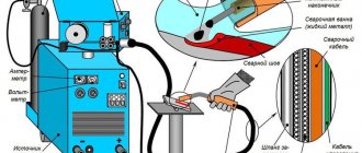
Standard consumable electrode welding consists of:
- inverter power supply (IPS);
- copper-plated wire feed unit;
- special burner
- mass crocodile
- shielding gas cylinder with flow meter.
There are inverters in which the SMPS and the feed mechanism are assembled under one housing. Such devices, operating on the “all-in-one” principle, are most often purchased to satisfy personal needs:
- welding of sheet material (especially thin sheet),
- welding a canopy or gate at the dacha,
- installation of pipelines, etc.
And also for solving special issues, such as, for example, body repair of passenger cars at service stations.
In factory conditions, more powerful equipment is usually used, so the SMPS and wire feeding are separated in them.
The principle of operation of the semi-automatic device is simple: it rectifies the alternating current entering the input into direct current at the output. At constant current, the current vector is determined by its polarity and how the cable is connected to the terminals.
The wire used is designed for a specific polarity. For common wire type 09G2S, “+” DC current is used on the torch.
During the welding process, when the distance from the consumable electrode to the metal changes, the working current and voltage are automatically adjusted so that the arc does not break. The SMPS “tries” to keep the voltage constant while the current increases or decreases.
The feed mechanism block consists of a spindle on which the reel is fixed, and the wire enters the hole of the feed roller through a guide. The feed wheel is designed for a specific wire diameter and can be replaced.
We have examined frequently repeated questions asked by novice welders who are learning to work on a semi-automatic inverter-type machine.
What protective gas is used when working with a semi-automatic machine?
Semi-automatic welding is carried out in a carbon dioxide environment, which is 100% carbon dioxide. You can work exclusively in argon, or in a mixture of argon and carbon dioxide. The welding wire, which is also an additive, is coated with a copper layer to improve electrical contact and smoothness of its feeding.
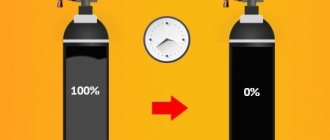
What should the shielding gas pressure be?
Choose 0.6 ... 0.8 MPa. This is if everything is fine and a new burner is used. If it wears out, you can add a little gas. The main thing is that there are no pores in the weld. If porosity does occur, then the pressure is insufficient (or very high, which can cause air to enter the welding zone, especially when working with an outer corner). Pores can also arise due to “dirty” gas, if there is be wind or drafts. The purity of the gas is especially noticeable when welding aluminum - the seam will simply become covered with a layer of soot and burning. When working with aluminum, choose only high-purity argon.
| Read the article on the website: Welding aluminum - instructions, apparatus, wire, gas |
What wire do you use? What polarity should be observed?
Copper-plated welding wire OK Autrod 12.51 ESAB
The most universal is 08G2S, all welders without exception are familiar with it. It is used for welding low-carbon and electrical steels. Naturally, this material is now sold under various trademarks. The world-famous company ESAB produces 08G2S under the name OK Autrod 12.51 - its composition is strictly controlled, which ensures stable mechanical properties of the seam. Also subject to control is the condition of the copper-plated surface, which is applied in a layer that is not too thick and not too thin, i.e. has an optimal size. Why is it important? Because low-quality wire quickly leads to failure of the feeding mechanism due to contamination with copper dust and chips.
The quality of the wire and copper coating directly determines the condition of the seam and the feed body.
Solid wire welding is carried out using reverse polarity current, that is, the torch is connected to the output with a plus sign. Also for corrosion-resistant steels, the additive ER-308 LSi is used - it contains 20% chromium and 10% nickel - exactly the ratio that gives the weld the greatest resistance to corrosion.
Is welding possible without shielding gas? If yes, what are its features? What are the pros and cons of this welding method?
Flux Cored Self Shielding Wire E71T-GS
It is possible to do without inert/active gases. In such cases, flux-cored wire is used, which is similar in its action to the piece electrode used in manual arc welding.
Flux-cored wire is a hollow tube filled with flux. During combustion, the latter provides the necessary gas protection from external influences for the correct formation of the weld.
Flux-cored wire is also often called flux-cored wire; it is less rigid than regular wire, therefore, in order to work correctly with it without stopping the feed mechanism, it is necessary to loosen the compression force of the roller. Or you shouldn't tighten it too much.
The wire is soft and will wrinkle. In order to avoid such problems, before feeding it for the first time, you should remove the tip on the burner and only then pull it through. Only install a tip of the appropriate size. There is no need to install a nozzle, since welding will be carried out without shielding gas. On the inverter, you should set the voltage, feed rate and inductance parameters using the smooth adjustment knobs.
Another peculiarity of working with such wire is the need to change the polarity on a semi-automatic inverter. The welder must be adapted for this. For example, on the OVERMAN 180 device, the polarity is changed inside the case next to the feed mechanism (the terminals are unscrewed and the wires are swapped). Do not forget also that the size of the feed roller groove must correspond to the diameter of the wire.
Welding a sheet 1-2 mm thick should be done with short seams at an angle back, in which case the seam is formed much better. For welding thin metal, 0.8 mm wire is commercially available. Maximum diameter 2.4 mm – for serious industrial applications.
Advantages:
- no need to carry heavy cylinders, mobility.
Flaws:
- high cost of wire,
- you need to be careful about its quality,
- A slag crust forms on the surface of the seam, which needs to be cleaned off.
| Read the article on the website: Semi-automatic welding for beginners |
One thought on “Semi-automatic welding with and without gas. Wire. Recommendations. ”
Add a comment Cancel reply
You must be logged in to post a comment.
When performing welding work, the main attention is paid to connecting the parts being joined. This factor largely depends on the correct settings of the welding equipment. When working with semi-automatic machines, you should adjust not only the current strength, but also set the desired polarity when welding with an inverter. The default settings do not allow you to fully solve the assigned tasks, especially when it comes to rare materials or high-alloy steels. Nevertheless, any inverter can be configured in the desired mode and get a high-quality seam.
Dependence on the type of voltage
If you cook on alternating current, the arc goes out and flares up when the sine wave passes zero. At high-frequency voltage this change is visually invisible. The type of current determines arc constancy. On a machine with a constant indicator, welding capabilities are expanded, since you can change the direction of electron movement and arc density. This will affect the connecting force.
We recommend reading: How to adjust the welding current
The influence of the type and polarity of the current is explained by the release of different amounts of heat.
On alternating voltage generators, the cable is connected in any configuration. The type of current should be taken into account when selecting electrodes. The recommended parameters are indicated on the box or in the instructions for consumables. It is more practical to work with universal elements designed for the possibility of changing poles.
How does forward and reverse polarity affect welding?
The very concept of polarity, in relation to welding equipment, means one or another connection option associated with current processes and the need to solve a specific problem. In order to change the polarity, you just need to swap the connection terminals. The current will change its direction and the physical processes, and the welding itself will proceed differently in each case.
There are two types of polarity that can be adjusted before performing work:
- Straight polarity. Installed on the equipment before joining thick workpieces with deep seams. In this case, the electrode is connected to the negative terminal, and the metal being welded is connected to the positive terminal. Due to straight polarity, so-called anodic and cathode spots appear during the welding process. A hotter anode spot appears on the workpiece side. Due to this, the base metal is melted to a great depth, making it possible to weld cast iron, aluminum and other workpieces made of complex metals.
- Reverse polarity. With this connection, the plus is connected to the electrode, and the minus is connected to the metal workpiece. An anode spot with an increased temperature appears on the opposite side, that is, on the electrode. The metal remains relatively cold, but the electrode heats up. This joining method allows you to weld thin-walled workpieces.
In accordance with specific tasks, the welder adjusts the forward and reverse polarity when welding with an inverter. Some young specialists do not know all the specifics of setting, so they sometimes have difficulty heating and melting workpieces made of different materials. It is recommended to first study the technical documentation of inverter welding and test the theory with practical actions.
Connection differences
The difference in connection is due to the polar redistribution of the workpiece and the electrode holder. With the direct method, electrons move to the workpiece, and a minus tends to the electrode end. The arc is characterized by increased compactness and density. On the “return” the plus goes to the holder, the place of contact of the thermal spot with the metal is scattered.
The method of connecting the poles is determined by the physical parameters and thickness of the part.
Specifications for polarity selection
The polarity of the connection is selected based on the technical conditions necessary to solve a specific problem. By changing the connection type, it is possible to obtain a concentration of the anode hot spot either on the workpiece itself or on the electrode. Direct heating is carried out due to the positive terminal, so direct connection to it leads to heating of this area.
This connection feature makes it possible to select the operating mode taking into account the following factors.
Thickness of metal workpiece
When welding parts with medium and large thickness, you should use a direct connection. In this case, thermal energy is concentrated on the product itself, helping to obtain a deep weld. In the same mode, it is possible to cut metals, regardless of their thickness. For welding thin sheet metals, it is recommended to use reverse polarity, where the main heat is concentrated on the electrode. Due to this, it is possible to avoid overheating of the workpieces, and the melting of the electrode will occur much faster.
Types of metals to be welded
The ability to change the location of the anode heat spot allows you to select the operating mode that is most effective for a specific part. For example, when welding cast iron or stainless steel, reverse polarity is used when welding with an inverter so as not to overheat the alloy and form a reliable connection. Aluminum, on the contrary, needs to be welded in direct connection mode in order to overcome the oxidative film as quickly as possible. There are recommendations for setting up equipment for specific alloys, which should be carefully studied and used in practice.
Type of welding wire or electrode
These components also differ in their individual temperature regimes, which largely depend on the fluxes used. If welding is performed with carbon electrodes, then connecting in reverse polarity mode is not suitable, since the flux will be subject to severe overheating and the electrode will become unsuitable for work. In such cases, choosing the most appropriate settings depends entirely on the type of flux and wire.
Sometimes the metal and electrodes require completely different settings, and the welder has to select the most optimal combination of work cycles and amperage. In addition, it is necessary to take into account the manufacturer’s recommendations reflected in the technical documentation.
What criteria should you use to choose polarity?
When choosing the type of connection for a welding machine, you need to pay attention to a number of important criteria. This will prevent defects or excessive consumption of materials and ensure the required strength of the connection.
Sheet metal thickness
Parts whose thickness does not exceed 3 mm are often burned through. To weld such workpieces, a reverse-polar scheme is used, providing an anode thermal spot at the edge of the electrode. This approach is appropriate when processing non-ferrous, alloyed materials.
We recommend reading: How to weld heating pipes using electric welding
Types of metals
The positive terminal is responsible for the final heating of the products and the holder. The cathode generates less heat than the anode. When machining refractory steels, it is better to use direct connection when the temperature reaches 4000 °C. For metals that change characteristics when overheated, connect the negative terminal. With direct-polar processing, the seam deepens; with “reverse” processing, it concentrates on the surface.
Types of electrodes
When choosing the brand of electrodes, take into account the type of current. Any variety is suitable for alternating voltage, since polarity does not play any role in this case. For varieties OK, OZS, MR, reverse connection is recommended. UONII and similar modifications are designed for a direct circuit. Manufacturers' recommendations are indicated on the packaging. Many welders prefer universal analogs to other options.
Features of welding with direct and reverse polarity
The direct and reverse polarity of the inverter have individual properties that must be taken into account when performing welding work.
Features of welding when connecting an inverter with direct polarity:
- Electrodes and filler materials melt during operation and are transferred into the weld pool in the form of large metal drops. This leads to increased metal spattering and an increase in the penetration coefficient.
- The direct connection mode is characterized by instability of the electric arc.
- On one side of the workpiece, the depth of welding is reduced, and on the other, the amount of carbon introduced into the metal mass of the part is reduced.
- The metal is heated correctly, its structure is not damaged and remains unchanged.
- The welding wire or electrode heats up less, which makes it possible to increase the current if necessary.
- Certain welding materials are characterized by an increased deposition rate, especially when consumable electrodes are used in active and inert gases. The same effect is obtained when additives interact with certain types of fluxes.
- Straight polarity during welding affects the structure of the material remaining inside the seam between the welded metal parts. The result is a composition containing manganese and silicon in the complete absence of carbon.
Reverse polarity when welding with an inverter is necessarily used when workpieces made of thin sheet metals are welded. This process requires attention and caution, since there is a high probability of burning and damaging the material. This connection mode is complemented by other methods to avoid inadvertent damage.
Among them are the following:
- A decrease in current strength, causing a decrease in temperature on the surface of the workpiece.
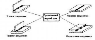
- It is recommended to use an intermittent weld during the welding process. First, several sections are welded in different places, after which they are connected to each other into a single whole. This scheme may vary depending on the specific conditions of the metal connection. In this way, it is possible to prevent deformation of metal workpieces, especially if their length exceeds 20 cm. A larger number of segments makes each section shorter, and the metal warps much less due to this.
- Welding of workpieces that are too thin is carried out with a periodically interrupted electric arc. The electrode quickly leaves the working area and immediately returns to its place and is ignited. The process runs almost continuously.
- When joining with an overlap, the pressure of the workpieces against each other should be as tight and airtight as possible. The presence of even a slight air gap can cause burning of the part located on top. You can create a tight fit using some kind of weight or clamps.
- When making butt joints, it is necessary to ensure a minimum gap between the products being welded. Ideally, there should be no gap at all.
- If thin sheet workpieces have too uneven edges, then a material is placed under the welding joint in this place to compensate for excess heat. Copper or steel plates are best suited for these purposes, the thickness of which should preferably be chosen as large as possible.
For beginners who have just begun to master this type of connection, we recommend training welding with reverse polarity on damaged metal sheets. This will make it possible to feel all the features of the process and in the future avoid burns and other defects.
MIG/MAG welding was invented in the 1950s and the basic principles are still used in modern welding machines today. It is the most versatile and often used in body repair. When we talk about semi-automatic welding, this is exactly what we mean. Unlike other types of manual welding, it is easy to use and still produces high-quality results.
p, blockquote 1,0,0,0,0 —>
A more correct and complete name for this type of welding is GMAW (Gas metal arc welding - electric arc welding of metal in a shielding gas environment), but the abbreviation MIG / MAG (Metal Inert Gas / Metal Active Gas) is more often used.
Theory of semi-automatic welding
The profession of a welder, like any other, requires certain training, because you will have to work with an electrical device that has several modes. Even if an experienced welder takes on the training directly at the place of work, he will in any case, before allowing the student to make the first seam, teach him a number of theoretical lessons.
General structure of a semi-automatic welding machine
Semi-automatic welding machine is suitable for welding ferrous and non-ferrous metals of various thicknesses Source svarkagid.ru
Each semi-automatic welding machine has an inverter, where there is space for installing a spool of wire, which is fed automatically. This wire, in fact, is nothing more than a consumable electrode. Devices of this type provide the ability to independently adjust the wire feed speed and current strength, guided by production needs.
Depending on the modification of the device, it has one or another set of functions, therefore, each unit can be used to perform different jobs in work processes. Of course, for novice welders, the simplest devices are needed, where control is limited to a few functions or has synergetic control, which greatly facilitates its setup. Professionals often prefer three-phase semi-automatic devices, if, of course, it is possible to connect them to a 380 V network.
In general, the working configuration of the welding machine consists of:
- welding unit;
- semi-automatic burners;
- cylinder with reducer;
- gas supply hose;
- cable with a crocodile clip for grounding the product during operation.
Selecting the right gas in relation to the metal
Accessories for cylinders: valves, tips, flow regulators, supply reducers, etc.
purchased separately Source lagma.ua In a semi-automatic machine, any gas performs a protective function - it isolates the welding site (bath, electrode) from contact with air, but depending on the metal or its thickness, the requirements may change - the gas can be active, inert, or it's a mixture of them. If we talk about the most common ones, these are carbon dioxide (CO2) and argon (Ar), which significantly reduces metal spattering, therefore, increases the strength and aesthetic qualities of the weld.
| Steel | Gas |
| Structural | CO2 |
| Structural | CO2+Ar |
| Stainless | CO2+Ar |
| Alloyed | CO2+Ar |
| Duralumin | Ar |
Note: gas cylinders are expensive in any case, but the larger their volume, the cheaper it is for the buyer.
Operating principle
p, blockquote 7,0,0,0,0 —>
MIG / MAG welding (Metal Inert Gas / Metal Active Gas) is carried out using an electric arc, protected by gas, formed between the working surface and the wire (electrode), which automatically flows to the welding site when the trigger is pulled. Wire feed speed, welding voltage and gas quantity are preset. Due to the fact that the welding wire is automatically supplied to the welding site, and only the manipulation of the welding torch depends on the welder, this type of welding is often called semi-automatic.
p, blockquote 8,0,0,0,0 —>
When MIG/MAG welding, setting up the welding machine is very important. With stick welding and TIG welding, the settings are not as critical. The cleanliness of the metal before welding is also important.
p, blockquote 9,0,0,0,0 —>
The end of the wire must protrude a certain distance, otherwise an electrode wire that is too long will not allow the shielding gas to operate normally. We will look at this option later in this article.
p, blockquote 10,0,0,0,0 —>
Shielding gas
The main task of the shielding gas is to protect the molten metal from atmospheric influences (oxygen oxidizes, and nitrogen and moisture from the air cause porosity of the weld) and to provide favorable conditions for ignition of the welding arc.
p, blockquote 12,0,0,0,0 —>
The type of shielding gas affects the melting rate, penetration of the welding arc, the amount of weld spatter, the shape and mechanical properties of the weld. A certain mixture of gases has a significant effect on the stability of the electric arc and reduces the amount of spatter during welding. The composition of the gas affects how the molten metal is transferred from the wire to the welding site.
p, blockquote 13,0,0,0,0 —>
Inert gases and their mixtures as shielding gas (MIG) are used for welding aluminum and non-ferrous metals. Argon and helium are usually used.
p, blockquote 14,0,0,0,0 —>
Active gases and mixtures (MAG) are used for welding steels. Most often it is pure carbon dioxide (CO2), and also mixed with argon.
p, blockquote 15,0,1,0,0 —>
Let us consider the types and mixtures of protective gases in more detail:
p, blockquote 16,0,0,0,0 —>
- Pure carbon dioxide (CO2) or carbon dioxide with argon, as well as argon mixed with oxygen, are commonly used to weld steel. If you use carbon dioxide (CO2) as a shielding gas, you will get a high melting rate, better arc penetration, and a wide and convex weld profile. When pure carbon dioxide is used, a complex interaction of forces occurs around the molten metal droplets at the tip of the nozzle. These unbalanced forces cause the formation of large, unstable droplets that are transferred into the welding zone by random movements. This causes increased spatter around the weld seam. Also, pure carbon dioxide produces more fumes.
- Argon, helium and argon-helium mixture are used in welding non-ferrous metals and their alloys. These inert gas mixtures produce lower melting rates, less penetration and a narrower weld bead. Argon is cheaper than helium and helium-argon mixtures, and also produces less spatter during welding. Unlike argon, helium gives better penetration, a higher melting rate and a convex weld profile. But when helium is used, the welding voltage increases for the same welding arc length and the shielding gas consumption increases compared to argon. Pure argon is not suitable for welding steel as the arc becomes too unstable.
- The universal mixture for carbon steel consists of 75% argon and 25% carbon dioxide (may be designated 74/25 or C25). When using such a shielding gas, the least amount of spatter is generated and the likelihood of burning through thin metals is reduced.
Tables
Yes, experienced craftsmen are able to select the correct welding mode on the spot, as their experience and knowledge allow. But what should beginners do? A special table for setting up the mode will help them. More precisely, tables for each type of welding. But don’t overuse ready-made settings, experiment and don’t be afraid to put your experience into practice.
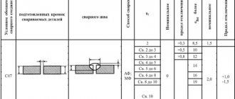
Table No. 1. Recommended settings for forming a butt weld in the lower spatial position and welding low-carbon and low-alloy steel in a shielding gas environment (carbon dioxide, a mixture of carbon dioxide with oxygen, and a mixture of argon with carbon dioxide) with reverse polarity current.
Table No. 2. Recommended settings for forming rotary butt joints using carbon dioxide, a mixture of argon with carbon dioxide and argon with carbon dioxide and oxygen, reverse polarity current.
Table No. 3. Recommended settings for forming an overlap weld with reverse polarity current, using carbon dioxide or a mixture of carbon dioxide and argon.
Table No. 4. Recommended settings for welding carbon steel, the spatial position is vertical, reverse polarity is used, as well as carbon dioxide or a mixture of carbon dioxide and argon.
How to hold a welding torch
p, blockquote 18,0,0,0,0 —>
The semi-automatic MIG/MAG welding torch can be operated with one hand, but using two hands will facilitate control and increase the accuracy and quality of the weld. The idea is to hold the burner with one hand and rest it on the other hand. This makes it easier to control the distance from the surface to be welded and the angle, as well as make the necessary movements with the torch when forming a seam.
p, blockquote 19,0,0,0,0 —>
To work with two hands, you need to use a full-size welding helmet (preferably with auto-darkening), which is held on your head and your hands remain free.
p, blockquote 20,0,0,0,0 —>
Video description
Selecting polarity for semi-automatic welding.
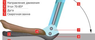
Torch position and movement
The semi-automatic MIG/MAG welding torch can be operated with one hand, but using two hands will facilitate control and increase the accuracy and quality of the weld.
Source svarkagid.com If we talk about the angle of inclination of the torch mouthpiece, then on average it can be 45-60° relative to the weld pool. But here several factors are taken into account at once, these are the type and thickness of the metal. That is, the larger the angle, the faster the metal heats up, therefore, when the mouthpiece is positioned 90° to the workpiece (strictly perpendicular), the heating will be most intense.
Of great importance for the mechanical quality and aesthetics of the seam is the factor of the distance between the welded edges and the core of the flame - the most optimal option is 2-6 mm from the edge of the torch, where the temperature is maximum. In this case, the additive is either immersed in the bath or located in the reduction zone.
Also, the quality and aesthetics of the seam depends on the movement of the torch during welding work and it can be carried out:
- for connecting workpieces of medium thickness - with a crescent, in increments of 2 to 5 mm;
- for thick-walled workpieces - with a delay of the torch along the weld pool;
- for thin sheets - with slight deviations to the sides;
- for workpieces of medium thickness - loops (rings).
Welding speed
The speed of movement of the welding torch must be controlled by the welder and correspond to the wire feed speed and voltage Source instrumentsmitino.rf
The speed of the welding process is under the control of the welder himself, that is, it depends on him at what speed the electric arc will pass through the junction of the workpieces. On the other hand, the welder does not have unlimited freedom of action, since he must adapt to the voltage of the arch and the intensity of the wire feed. The last two factors are also dependent - they are set in accordance with the metal, the thickness of the workpieces being welded and the shape of the seam.
Movement of the welding torch during welding
p, blockquote 21,0,0,0,0 —>
- A straight weld, without any sideways movement, can be used on metals of almost any thickness, but it requires some experience to make sure that the welding arc acts evenly on both metals being welded.
- When welding metal parts with a thickness of less than 1 mm, it is better to use electrode wire of a smaller diameter, reduce the current parameters, as well as the wire feed speed. You need to cook in short bursts, taking a break between them within 1 second so that the metal has time to cool. A short break is needed so that the next segment merges with the previous one and a monolithic sealed seam is obtained.
- When welding a long segment, in order to avoid overheating of the metal and thermal deformation, you can weld in small segments or points at intervals, alternately, from one or the other end of the welded segment. Thus, it is possible to weld the entire segment without causing thermal deformation of the sheet metal.
Electrode type
To determine the polarity, it is necessary to take into account the main characteristics of the electrode: types of anode spot, type of flux and temperature. The following types of electrical conductors are distinguished depending on technical characteristics:
- TsL-11: used when welding using reverse polarity schemes. These electrodes are capable of treating the surface of metals made of dense stainless steel and other iron alloys with high resistance to corrosion. They provide high quality welds without destroying the protective layer of metal. TsL-11 electrode rods are coated with a special solution of phosphorus and potassium. It protects the weld seam from the negative effects of the environment. Electrical conductors TsL-11 must be stored in dry rooms. When using them, it is recommended to use short arcs, which ensures better metal penetration.
- NIAT-1: used for connecting parts of small thickness when connecting cables using a reverse polarity scheme. These electrodes have anti-corrosion properties. They are resistant to heavy loads. These conductors increase the strength of the welding joint. The composition of NIAT-1 electrical conductors includes magnesium, molybdenum, carbon, nickel and silicates. These chemical elements have low deposition rates (up to 10 g/Ah), which increases the productivity of the electrode. Before using electrical conductors, it is recommended to heat treat them in specialized ovens. Calcination of the electrodes must be carried out within 1 hour.
- OZL-8: used when processing non-ferrous metals with direct polarity current. They can function in operating environments with temperatures below 1000°C. These electrical conductors have anti-corrosion properties. Therefore, they can be used for processing alloy steels. Electrode rods OZL-8 are made on the basis of a small rod of welding wire with a diameter of up to 5 mm. The deposition rate of these electrical conductors is no more than 13 g/Ah, the yield strength is 400 MPa. For surfacing 1 kg of welding seam, 600 g of OZL-8 electrodes are required.
When using electrodes, the following rules must be observed:
- Before welding metal parts, thoroughly clean the electrical conductor rods.
- Treat the parts to be welded with a chemical solution that protects their surface from dust and other types of contaminants. It also makes the metal shine.
- When using new electrodes, they must first be calcined in special drying ovens.
- In the process of welding workpieces, it is necessary to keep the electrode rod perpendicular to the axis of the weld.
- Keep the electric arc at a distance of 3 mm from the edges to be welded.
- During welding, do not make sudden jerks. Otherwise, the seam pattern will change.
- To avoid the formation of porous surfaces, it is necessary to clean the workpieces from slag and residues of the molten electrode.
- A sharp drop in the temperature of the electrical conductor should not be allowed. Otherwise, the tool may become partially deformed.
The nuances of operating electrodes at different polarities are indicated in the instructions drawn up during the manufacture of these instruments. They are published on the official websites of electrical conductor manufacturers.
Welding speed
p, blockquote 22,0,0,0,0 —>
Welding speed is the speed at which the electric arc travels along the welding site. It is controlled by a welder.
p, blockquote 23,0,0,0,0 —>
The speed of movement of the welding torch must be controlled by the welder and correspond to the wire feed speed and arc voltage selected in accordance with the thickness of the metal being welded and the shape of the seam.
p, blockquote 24,0,0,0,0 —>
It is important to achieve the correct welding speed. Too high a speed may cause too much molten metal to splash. Shielding gas can remain in the rapidly solidifying molten metal, forming pores. Welding speeds that are too slow can cause excessive penetration of the welding arc into the metal being welded.
p, blockquote 25,0,0,0,0 —>
Shielding gas flow rate
Can significantly affect welding quality. The flow rate of the shielding gas must strictly match the wire feed speed. A flow rate that is too slow will not provide adequate oxidation protection, while a shielding gas flow rate that is too high may create turbulence that will also interfere with proper protection. All deviations lead to porosity of the weld. It is important to create a smooth air flow, without turbulence. This may be affected by the presence of frozen splashes on the nozzle.
p, blockquote 27,0,0,0,0 —>
Welding torch angle during welding
MIG/MAG welding can weld different parts at different angles, so there is no universal angle to follow when welding. When welding parts lying in the same plane, an angle of 15–20 degrees (from the vertical position) would be ideal. When welding two parts at an angle, it is more convenient to hold the torch at an angle of 45 degrees. With practice, you can determine for yourself the most convenient angle in a particular situation.
p, blockquote 28,0,0,0,0 —>
Welding voltage (electric arc length)
Arc length is one of the most important variables to control in MIG/MAG welding. The normal welding arc voltage in carbon dioxide (CO2) and helium (He) is much higher than in Arone (Ar). Arc voltage affects weld penetration, strength and width.
p, blockquote 29,0,0,0,0 —>
As the electric arc voltage increases, the weld becomes flatter and wider and penetration increases to a certain extent. Low tension produces a narrower, more convex weld and less penetration.
p, blockquote 30,1,0,0,0 —>
Too much and too little voltage causes arc instability. Excessive stress causes spatter and porosity in the weld.
p, blockquote 31,0,0,0,0 —>
External influence on settings
Changing the spatial position of the seam, strengthening the leg, thickness, and configuration of the joints of one metal will require different settings. Basic settings of a semi-automatic machine (PA):
- Arc voltage; the adjustment is reflected in the change in current value.
- Current – wire feed; An increase in wire feed speed is responded to by a proportional increase in the current value and vice versa.
- Gas consumption is set based on the main parameters and is regulated by assessing the quality of the seam while excluding pore formation.
Further, based on the results of the test pass, the modes of electric arc welding in a shielding gas environment are adjusted.
For an experienced practitioner, even the sound of a lit arc is informative. Once you purchase a semi-automatic machine, you will have to get used to its features and the need to adjust to changes:
- The configuration and assembly of PAs with equivalent characteristics differ in their filling; differences in configuration are found among the same manufacturer.
- Voltage fluctuations disrupt settings; the transformer PA will turn off, and the inverter may burn out.
- Changing the composition of the shielding gas.
- Changing the brand and diameter of the wire.
- Even minor repairs or replacement of components will have an impact.
Gas protection
Gas flow also refers to calculated tabular values . Does not directly affect the settings of the semi-automatic welding machine. Control is simplified if the gearbox is equipped with 2 scales. Registration of the reduced flow value is perceived more objectively with the installation of a rotameter.
The rotametric flow meter shows the supply of carbon dioxide (argon) working pressure in constant values. The static pressure reading will drop when the burner trigger is triggered, creating a protective cloud. The initial range for the rotameter is 6–10 l/min, for a gearbox with pressure gauges – 1–2 atm.
Economical consumption is selected according to the porosity of the seam: the gas flow increases until the pores disappear . In a room with forced exhaust and in the wind, in order to save money, it is preferable to use cored self-protecting wire.
Selection of gas mixture
The choice of mixture is determined by the quality requirements and material properties:
- CO2 is an ideal protection for the weld pool of structural steels, deep penetration, but the spattering and roughness of the weld are not suitable for fine work.
- A mixture of argon and carbon dioxide C25 (75% Ar; 25% CO2) - the combination is suitable for welding thin-sheet structures, creating a uniform seam with a minimum of splashes.
- Composition of 98% Ar; 2% CO2 – for stainless steels.
- For aluminum – argon in its pure form.
Voltage setting
The power consumption for burning the arc and melting the metal is determined by the voltage setting. Energy consumption increases with increasing penetration depth (material thickness) and wire diameter.
The settings of household PAs are stepped. Coarsening with min/max modes or multi-mode, with soft adjustment as an extended range of adjustment of the welding voltage of the Wester MIG-110i semi-automatic machine for 10 settings.
On the inside of the casing cover there is a table of regulations for voltage settings . This is the manufacturer’s main hint; it is printed on models that differ in power and technical equipment.
The final solution is how to set up a semi-automatic welding machine for the operator. Vague recommendations are not dogma, the main criterion is the depth of penetration and the strength of the connection.
Wire feed speed
The wire feed speed controller controls the current intensity . The feed amount is one of the main variable characteristics. Set after voltage selection: the melting speed determines the movement of the electrode in the burner.
This value is subject to adjustment after changing the brand and diameter of the wire, changing the voltage. There are PAs with automatic mode adjustment, but they are in the segment of expensive equipment.
Fine-tuning the movement of consumables to optimize adjustments is desirable . Excessive acceleration will lead to sagging, deceleration will lead to subsidence, waviness, and seam breaks. The balance of current and voltage, controlled by the feed rate, adds up to an optimal roller.
The first indicator of a mode discrepancy is revealed in action - the feed speed with the ignited arc decreases, but the wire does not have time to melt, bends, sticks to the workpiece, and active spatter occurs.
Insufficient supply - the inverter electrode burns out before touching, the tip becomes clogged. Selecting the speed/current mode for the set voltage is the first step towards professionalism .
Wire feed speeds in a semi-automatic machine, a table of the direct relationship of the effect of changing settings on the final result:
Polarity
The procedure for changing polarity is simple. Under the cover there is a sign indicating which type of metal and wire require direct or reverse polarity. Direct - the burner is connected to the minus terminal. With straight polarity, the melting of the wire is accelerated by 50%, but the stability of the arc decreases.
Welding with self-shielding flux-cored wire is carried out with straight polarity . The maximum heat generation energy is spent on protecting the seam. The flux will react without any residue. The tendency to splash is compensated by indifference to under-cleaning of work areas and gusts of wind. Costs in the form of splashes and slag crusts are a necessary evil.
A solid copper plate in a gas cloud is connected to the positive terminal . Preparing material for welding involves cleaning up signs of corrosion, contamination of joints, and cutting. Conductivity increases with increasing diameter. For large cross-section workpieces, there is a reason to increase the wire cross-section.
Wire ejection and release
The length of the consumable electrode extending from the contact tube (tip) and the size of the working gap of the torch affect the quality of the permanent connection.
The relative position of the burner tip relative to the nozzle varies in individual designs. They are located at the same level, the contact tube is recessed or extended relative to the nozzle up to 3.2 mm.
At a short reach, welding of structural low-alloy steels is carried out - increasing the distance thins the cover with protective gas. The flux-cored wire is artificially lengthened to increase the melting point .
Arc setting
Already simple PA models have a vernier control over inductance values . Setting the hardness changes the temperature of the arc and the depth of penetration with a noticeable convexity of the seam. Parts are sensitive to overheating and thin walls no longer interfere with welding.
Reducing the compression of the current channel (increasing inductance) raises the melting temperature, the penetration is deep, and the weld pool liquefies. The seam bead is flattened. Controlling the penetration depth, arc and bath temperature is a qualitatively new level of setting up a semi-automatic welding machine.
Small diameters of the additive make the arc more stable, the deposition rate increases, the penetration depth is optimized, and spatter is reduced. Based on the convexity of the seam and the amount of spattering, the length of the arc is specified: a short one gives a volumetric seam, a long one interferes with the concentration of the melt .
| Inductance max | Inductance min |
| The penetration deepens | Low temperature arc |
| Weld pool liquefaction | Splashing increased |
| The seam bead is even and smooth | Volumetric seam bead |
| Corner, reinforced seams | Setting up a semi-automatic machine for welding thin metal |
Wire feed speed control
The wire feed activation switch can be two-position (High/Low) or multi-stage. Larger diameter solder is dispensed at a slower rate, optimizing the process.
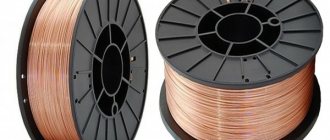
Welding wire
Welding wire serves as filler material. When welding, the wire enters the seam and melts along with the edges of the metals, filling the seam. It must have a chemical composition similar to the composition of the materials being welded. For example, the carbon content, on which the ductility of the weld depends.
p, blockquote 32,0,0,0,0 —>
The melting point of the electrode wire should be slightly lower or the same as the metals being welded. If the wire melts later than the metal being welded, then the likelihood of burning through the metal increases.
p, blockquote 33,0,0,0,0 —>
For welding aluminum and its alloys, wire made of pure aluminum or with an admixture of magnesium and silicon is used.
p, blockquote 34,0,0,0,0 —>
Welding wire diameter
p, blockquote 35,0,0,0,0 —>
The diameter of the welding wire affects the size of the weld, the penetration depth of the welding arc, the strength of the weld and the welding speed.
p, blockquote 36,0,0,0,0 —>
A larger electrode (wire) diameter creates a weld with less penetration, but a wider one. The choice of wire diameter depends on the thickness of the metal being welded and the position of the parts being welded.
p, blockquote 37,0,0,0,0 —>
In most cases, a small wire diameter is suitable for thin metal and for welding in a vertical position.
p, blockquote 38,0,0,0,0 —>
Larger diameter wire is desirable for thicker metal. She needs to operate at a reduced wire feed speed due to lower penetration.
p, blockquote 39,0,0,0,0 —>
Semiautomatic welding inverter
The semi-automatic welding inverter is a fairly new unit on the welding equipment market. However, it is already very popular and is used everywhere for surfacing and welding metal products, parts and structures. These devices carry out welding on electrode wire, protected by inert gases.
Distinctive features of a semi-automatic machine from an inverter
Welding inverters gave impetus to the development of welding equipment, which is being improved every day. The development of welding technologies has also gained momentum. All these factors led to the creation of an inverter-type semi-automatic machine. Inverter machines have a lot of advantages compared to traditional designs, which makes it possible to say that inverters are the most popular type of welding equipment offered on the market. It's all about their design features.
Welding wire output length
p, blockquote 40,0,0,0,0 —>
Before touching the metal to be welded, the wire must protrude from the tip to a certain length.
p, blockquote 41,0,0,0,0 —>
This segment of wire conducts the welding current. Thus, increasing the length of this segment increases the electrical resistance and temperature of this piece of wire. The more the wire protrudes, the smaller the electric arc will be. With a long wire exit from the tip, a narrow seam, low penetration and increased seam thickness are obtained.
p, blockquote 42,0,0,0,0 —>
When reducing the length of the output of a piece of welding wire, it has the opposite effect. The penetration of the welding arc increases, resulting in a wider and thinner seam.
p, blockquote 43,0,0,0,0 —>
Typical welding wire output lengths range from 6mm to 13mm.
p, blockquote 44,0,0,0,0 —>
When using flux-cored wire without gas, the length of the welding wire output should be greater than with gas (30 - 45 mm).
p, blockquote 45,0,0,1,0 —>
Welding with self-shielding wire without gas
Self-shielding flux-cored wire, also called flux-cored wire, has a core containing all the necessary additives to protect the seam and welding arc during welding without gas.
p, blockquote 46,0,0,0,0 —>
Such wire contains components that form gas during welding, antioxidants, cleaners, and additives that improve the electric arc. Thus, when an arc occurs, a gas is formed that protects the molten metal, and special components form a kind of slag on top of the metal during cooling, which protects it during solidification.
p, blockquote 47,0,0,0,0 —>
p, blockquote 48,0,0,0,0 —>
This wire is convenient to use when a welding machine is not needed often. The advantage is better equipment mobility (no gas cylinder required) and the ability to be used outdoors (even in windy weather, due to the lack of protective gas flow).
p, blockquote 49,0,0,0,0 —>
When welding with self-shielded wire, a lot of smoke and fumes are generated and it is difficult to visually control the welding process. The welding flux that remains on top of the finished seam does not conduct electricity, so after cooling, in order to weld over the finished seam, it must first be cleaned off.
p, blockquote 50,0,0,0,0 —>
Flux cored wire can weld thicker metal than wire used with gas.
p, blockquote 51,0,0,0,0 —>
Welding with this type of wire “forgives” an insufficiently prepared surface.
p, blockquote 52,0,0,0,0 —>
Semi-automatic welding machine without gas
One of the most frequently asked questions about welding is “how does a semi-automatic welding machine without gas differ from a unit running on gas?” There are many different arguments and thoughts on this topic, but what is the main difference? Well, let's try to figure this out.
Generally speaking, using carbon dioxide (or semi-automatic gas welding machines) welding is carried out protected by an inert gas environment: here either ordinary carbon dioxide or a mixture of carbon dioxide and argon can be used. Since carbon dioxide blocks a process such as combustion, therefore, there are no high temperatures at the welding site, the metal does not burn through.
The semi-automatic welding machine, which does not use gas, uses a special wire coated with flux. During the welding process, the flux burns, releasing the same carbon dioxide, which also prevents the metal from burning.
Pros and cons of welding with and without gas
When welding without gas, the welding zone is completely protected. Flux creates a protective surface because flux is lighter than metal.
When welding with gas (for example, carbon dioxide), the welding conditions are the most favorable; in addition, the metal is cooled in the welding zone. This method is used a little more often. In addition, it is more profitable from an economic point of view.
However, quite a few people use the second welding option, mostly due to the fact that when using a welding machine without gas, the seam comes out more neat. Carefully!
When welding with a welding machine without gas, under no circumstances should you use ordinary wire. When using ordinary wire, the quality of the seam will be very low, it will turn out uneven, and will have holes. There will be a serious increase in wire consumption, since a significant amount of it will simply evaporate.
And most importantly, in the welding area (in the weld pool) the influence of oxygen will be observed, and therefore, oxides and many cavities will form in the weld. Which welding method you choose, with or without gas, is entirely your decision. And you can always easily pick up the equipment necessary for this in specialized stores.
Polarity when welding without gas
Polarity is the direction of flow of electricity in the welding machine circuit.
p, blockquote 53,0,0,0,0 —>
With straight polarity, the electrode (wire) is a minus, and the metal being welded (grounding) is a plus. With reverse polarity, the electrode is positive and the metal being welded is negative.
p, blockquote 54,0,0,0,0 —>
For welding using flux-cored wire, straight polarity is used (wire - minus, ground - plus).
p, blockquote 55,0,0,0,0 —>
When welding with gas – electrode (+), mass (-).
p, blockquote 56,0,0,0,0 —>
The polarity with which cored wire will work normally depends on its composition. There are also those that will weld normally with any polarity.
p, blockquote 57,0,0,0,0 —>
In most cases, when welding without gas, the welder should be set up with a positive ground and a negative electrode. This will give more power to melt the cored wire.
p, blockquote 58,0,0,0,0 —>
The sound of proper semi-automatic welding
When learning MIG / MAG welding, it is important to listen to the sounds made during welding and, of course, control the welding process visually (through a darkened mask). When welding correctly, a semi-automatic welding machine produces a sound reminiscent of frying meat in a frying pan. This "hissing-buzzing" sound indicates a good balance between wire feed speed, gas flow and voltage settings. Solidified spatter on the nozzle or tip of the welding torch impairs the flow of shielding gas, poor contact of the ground clamp, poorly cleaned welding area, all of these can impair the formation of the welding arc, and will be reflected in the welding sound. You can also read the article “how to set up a semi-automatic welding machine” for a better understanding of the correct settings of the machine before welding.
p, blockquote 59,0,0,0,0 —>