Welded structures are distinguished by a variety of ways to connect parts. The final strength depends on compliance with technological processes. Therefore, it is important to correctly mark welds on drawings.
The designation of the weld in the drawing and its interpretation depends on the type of connection.
Necessity of notation
For accurate and uniform reading of drawings, graphic symbols and text descriptions must comply with ESKD and GOST.
The need for designations is caused by the need to convey to the performer in a concise form the maximum amount of information, allowing him to immediately begin work.
The description indicates the following characteristics:
- type of material of the parts forming the weld;
- dimensions with tolerances;
- technologies used;
- size and shape of surfacing;
- strength properties and tightness requirements;
- conditions of technological processes and order of execution.
Designation options.
The quality of the welded joint is checked by comparing the actual characteristics with those stated in the technical documentation.
This leads to the need to standardize symbols on drawings to prevent discrepancies.
Non-standard cases
How is a weld seam indicated on the drawing if its dimensions do not fit within the GOST standards? In such a situation, the dimensions of all its elements should be included in the design documentation.
Then the performer, in the process of directly solving the problem, will be able to achieve the desired quality of the result, even taking into account the effect of residual stresses. The latter appear due to shortening deformation (which occurs due to uneven heating of surfaces) and are distributed depending on the selected mode, geometry and other factors. The thickness of the workpieces also cannot be discounted, because it can provoke plane or volumetric stresses.
GOST with requirements for weld markings
The assembly of a structure using welded joints is regulated by the following types of technical documentation:
- technological instructions;
- welding production project (WPP);
- separate sections of the general work project (WPP).
Example of designation according to GOST.
The main purpose of the listed documents is to ensure uniform reading and understanding of drawings and technological maps by engineers, workers and representatives of control services.
When assessing the quality of welded work, the following documentation is used:
- as-built drawings with changes made by the manufacturer or installer of structures;
- approval by the developer or design organization of the changes made;
- certificates for welded materials.
Operational control is carried out by the contractor, the foreman, to ensure that the work results comply with the requirements specified in the technological maps, approved instructions and state standards.
Types of welded joints
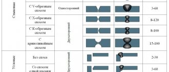
The type is determined by the relative position of the parts being connected. According to GOST 5264-80 and GOST 14771-76, there are five types of welded joints:
| No. | Name | Description | Marking |
| 1 | Butt | The elements to be joined are placed in the same plane, welded at adjacent ends, and edge processing is possible. Requires precise adjustment of joined parts and is highly durable. | WITH |
| 2 | Lap | Parallel planes of parts overlap each other. They are inferior to butt joints in terms of reliability under load, and are not so demanding in terms of accuracy of fit. | N |
| 3 | Tavrovy | The end of the part is welded to the surface of another part of the structure vertically or at an angle. Not recommended for bending loads. | T |
| 4 | Angular | The surfaces of the joints to be connected are inclined relative to each other (the angle of contact of the edges is more than 300), welding is carried out at the ends of the products. | U |
| 5 | Tortsevoy | The ends of the nodes whose side surfaces are in contact are connected. To do this, a layer of metal is fused to the ends. Used when connecting thin elements to avoid burning. | WITH |
| 6 | Special types of seams not provided for by GOST | ABOUT |
According to GOST, welded joints can be single-sided (SS) or double-sided (BS), depending on the metal deposit on one or both sides. There are also single-layer and multi-layer welding.
The choice of welding seam is determined by the design requirements for the connection.
Types of seams according to GOST standards (squares 2 and 3 examples)
Possible methods of connecting two elements are closely discussed in GOSTs 14771-76 and 5264-80. There are the following types of welding joints:
- C – butt seam. The two elements being connected are in the same plane and at the same level. They are connected to each other by adjacent ends. This is one of the most popular connection options. Its peculiarity lies in the fact that the mechanical characteristics of the weld are very high, and the appearance of the finished structure is aesthetic. Along with the positive aspects, there are also negative ones. This type of connection remains technically difficult. It can only be performed qualitatively by experienced specialists.
- T – T-seam. This implies a connection of two elements located at an angle of 90 degrees relative to each other, and the junction has a T-shaped configuration. This is the most rigid connection option of all those considered. Therefore, it is not used in cases where some elasticity is important for the finished structure.
- N – lap seam. Two workpieces are located parallel, but not in the same plane. They are in contact with some overlap of the plane. A fairly strong and reliable connection method, but in terms of rigidity it is inferior to the T-type version.
- U – fillet weld. The ends of two workpieces are positioned at an angle of 90 degrees. The ends melt, resulting in a fairly strong and rigid connection.
- O – special types. This designates all other options for welding workpieces that are not described in the standard.
Both GOST standards mentioned at the beginning of the section have common features and overlap with each other. For manual arc connection according to GOST 5264-80:
- C1 – C40 butt;
- U1 – U10 corner;
- H1 – H2 overlap;
- T1 – T9 tee.
Performing welding work in an inert environment in accordance with GOST 14771-76:
- U1 – U10 corner;
- C1 – C27 butt;
- H1 – H4 overlap;
- T1 – T10 tee.
Images for different types of welding
Each weld in a metal structure must be described and reflected in the design documentation. All seam symbols must comply with the interstate standard.
We recommend reading: What are the types of defects in welds?
The types of connections of welded parts are indicated in the drawings by 1 symbol. The transcript is presented in the table.
| Connection type | Description of properties | Designation on the drawing |
| Butt | The structural elements are located in the same plane and welded at the ends. The connection requires processing of the edges of the joint. | WITH |
| Angular | The structural elements are connected at an angle to each other with an angle of more than 30° between the ends. | U |
| End | The ends of the structural elements form such a connection so that their lateral planes touch. | WITH |
| overlap | The parts are superimposed on each other by the main planes. It is used in cases that do not require high accuracy of fit and matching of end contours. | N |
| Tavrovoe | One structural part is welded to the surface of another at an angle or vertically. | T |
Welding installation joints
WELDING DEFORMATIONS AND STRESSES
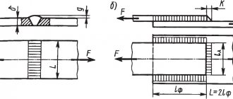
As noted above, when joining two sections of a structure during installation, the conditions for welding are the most difficult. Welding the entire section at the same time is completely impossible, and therefore, after applying some of the seams, the rest will be applied under conditions of fastening both sections to be welded.
So, for example, when welding an assembly joint of an I-beam, shortening of the first of the sheets being welded can still occur due to the bringing together of both sections and reducing the gap between the remaining sheets, but when applying subsequent seams, such a bringing together of the welded sections can no longer occur, since they are pushed apart by the first sheet . Therefore, if special measures are not taken to combat deformations and stresses when welding, it is necessary to weld first the butt seams of those cross-sectional elements that give the greatest shrinkage (the thickest seams), so that the stresses caused by welding the last butt seams in a fixed position, were the smallest. To prevent stresses from appearing in the structure, it is better to bend the sheets being welded. For example, if the wall joint is welded first (Fig. 216), then when welding the joint of the chords, the latter must be bent, as indicated in § 63. To make bending possible, it is necessary that
| Rice. 216. Welding the installation joint of an I-beam. |
The waist seams were undercooked to some length. After welding all joints, the remaining uncooked sections of the waist seams must be welded. At the same time, so that unequal shortening of the wall and belts (due to their different cross-sections) does not cause stress in the butt seams, it is advisable to start welding the belt seams from the joints (Fig. 216), taking into account
that the creation of somewhat unfavorable conditions at the junctions of the fillet assembly weld with the factory weld is less dangerous than the creation of stresses in the butt seams of the beam.
In cases where the use of preliminary reverse bending for one reason or another is impossible (for example, with an X-shaped butt seam of thick sheets), expansion of the joined sheets should be applied in order to increase the gap in the joint due to elastic compression deformations. In this case, the tightening forces during the welding process will not be transmitted through the entire structure to the fastenings, but will be absorbed by spacer jacks; after the seam has completely cooled, the elastic tensile deformations remaining in it will be removed upon release from the jacks due to elastic compression deformations in the rest of the structure.
In difficult cases, in addition to using special techniques, it is advisable to weld the seams with piercing.
The sequence of application of individual seams must be consistent with both the welding methods used and methods for combating warping and stress, and with the nature of the distribution of stresses from the payload in the section along the joint. Considering that the last butt welds are usually performed under the most severe conditions, the last to be performed are the seams (or sections of welds) located in those parts of the butt section that are least stressed by the payload. This rule can be deviated if the last closing seam is made using special measures (for example, bending) to ensure that it is free of dangerous stresses.
| Rice. 217. Layout of the installation joint on Liberty type ships. |
Insufficient attention to the welding sequence of assembly joints was one of the reasons for the appearance of cracks in the deck of Liberty-type ships. Ignoring special measures to combat deformations and stresses (and in particular the lack of use of preliminary bends) led to the fact that the deck sheets received very large depressions in the area of the installation joint (Fig. 217). The latter excluded a significant part of the deck flooring from participating in the work of the main design section of the ship, causing overstresses in those parts of the deck flooring that were not formed due to the longitudinal beams supporting them.
In addition, the lack of clear instructions on the sequence of seams at the hatch could lead to a sequence in which an already very overstressed section (due to the lack of rounding of the corners of the hatch) could be further weakened due to the occurrence of plastic deformations in the deck during the welding process and partial reduction deformation capacity of the metal decking. As a result of all these omissions, on a large number of Liberty-class vessels, emergency cracks appeared precisely in the area of the specified installation joint.
Without dwelling on the details, it should only be noted that without proper consideration of the sequence of application of welds, rational structural forms cannot be selected and the proper strength and operability of the structure cannot be ensured. The choice of welding sequence should be based on a clear understanding of all phenomena occurring during the welding process
[1] Due to the fact that in this guide the temperature in all* cases is indicated b
degrees Celsius, hereinafter the symbol of the Celsius scale is
[3] • 131
[4] = 2S. tg“.
If the general deformations of welded structures are greatly influenced by the sequence of application of individual seams, then the local deformations and deformations out of the plane of the sheets being welded are significantly influenced by the method of making each seam. ...
As noted above, when welding complex composite sections and structures, the nature of the resulting deformations depends on the order in which the seams are applied. Therefore, one of the main means of combating deformation in the manufacture of welded structures...
msd.com.ua
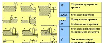
Auxiliary signs and notes
Solid thin lines are used to indicate visible welds, and dotted lines are used for invisible ones. In notes, supporting characters must be the same height as numbers. Features of the installation of welded structures in technical documentation are often indicated using additional symbols. They make it easier to read the drawing and clarify the conditions for processing the ends of parts.
Section 2 of GOST 2.312-72 provides a list of graphic symbols meaning:
- Elimination of convexities to the level of the main plane.
- Processing irregularities and forming a smooth transition to the surface of the parts to be joined.
- Creating a seam along an open line. The sign is used when its position is clear from the drawing.
- Formation of a spot or intermittent seam (chain placement) and with an inclination of 60°.
- Installation of structures with staggered placement of welded sections.
- Formation of a closed welded contour. This will be indicated by a sign with a diameter of up to 5 mm.
- The welded connection is created during the installation of the structure, i.e., at the place of its constant operation.
Auxiliary signs and meaning.
If it is necessary to add a description, it is made the same height as the previously made inscriptions.
Most often, the notes indicate the side to form the main connection:
- the surface is considered front if there is a one-sided seam on it;
- for a double-sided connection, the surface on which the main seam is made is considered to be the front surface;
- For a double-sided joint with symmetrical edges, any surface can be considered front.
We recommend reading Existing types of welded joints
MOUNTING SEAM is... What is MOUNTING SEAM?
- An assembly seam is an element of an abutment assembly, which is a combination of various insulating materials that fill the installation gap and have specified characteristics. [GOST 30971–2012] Term heading: Window and door blocks... ... Encyclopedia of terms, definitions and explanations of building materials
- Assembly seam - Assembly seam: an element of the abutment assembly, which is a combination of various insulating materials intended to fill the installation gap, and having specified characteristics... Source: GOST R 52749 2007. Assembly seams... ... Official terminology
- Assembly seam - 78. Assembly seam A weld performed during installation of a structure Source: GOST 2601 84: Welding of metals. Terms and definitions of basic concepts original document... Dictionary-reference book of terms of normative and technical documentation
- Forceful operational impact on the assembly seam is the impact arising from the mutual movements of the window frame (frame) and the wall opening when linear dimensions change due to temperature, humidity and other influences, as well as during shrinkage of buildings. Source: GOST 30971 2002: Assembly seams ... Dictionary of terms of normative and technical documentation
- Operational force impact on the installation seam is the impact on the installation seam resulting from deformations of the wall opening and frame of the window unit due to changes in temperature, humidity conditions and wind loads during operation. [GOST 30971–2012] Category... ... Encyclopedia of terms, definitions and explanations of building materials
- Forceful operational impact on the assembly seam is the impact arising from the mutual movements of the window frame (frame) and the wall opening when the linear dimensions change due to temperature, humidity and other influences, as well as during shrinkage of buildings... Source: GOST 30971 2002.... ... Official terminology
- STO 75298253-009-2008: Window assembly joints. Technical specifications - Terminology STO 75298253 009 2008: Window assembly joints. Specifications: 3.3 lateral installation gap: The installation gap between the end surface of the window frame and the adjacent surface of the window opening. Definitions of the term from different... ... Dictionary-reference book of terms of normative and technical documentation
- GOST R 52749-2007: Window installation joints with vapor-permeable self-expanding tapes. Technical specifications - Terminology GOST R 52749 2007: Window installation joints with vapor-permeable self-expanding tapes. Technical specifications original document: 3.3 lateral mounting gap: Mounting gap between the end surface of the window frame and the adjacent one... ... Dictionary of terms of normative and technical documentation
- node - 04/01/14 node (computing networks) (2): An object that is connected or connected to one or more other objects. Note In a network topology or abstract layout, nodes are points on a diagram. In... ... Dictionary-reference book of terms of normative and technical documentation
- An abutment unit is a structural system, generally consisting of an SPK box, an assembly seam, a fastening system, a part of the enclosing structure, limited by the area of distribution of thermal inhomogeneity on its inner surface near the opening... Dictionary-reference book of terms for normative and technical documentation
dic.academic.ru
Application rules and decoding features
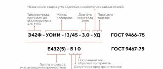
Explanations for welded joints in the drawings are given according to the ESKD rules. The joint is indicated by a one-way arrow coming from a horizontal line with inscriptions located above and/or below it.
The explanatory inscription consists of 9 blocks, the contents of which are:
- Indicates a closed circuit or an installation connection.
- Indicates the GOST to which the symbols used correspond.
- Indicates the type of seam (chain, checkerboard, interrupted).
- Provides the welding method according to the selected GOST.
- Gives the dimensions of structural elements and type according to the standards.
- Contains the length of the welded section in mm.
- Lists the connection type with additional characteristics.
- Shows additional characteristics such as stride length, etc.
- Contains requirements for the cleanliness of the surface of welded parts, which are represented by auxiliary signs. This parameter determines the need for mechanical cleaning of the ends.
The designations of welded joints recommended by the standards and examples of production practice do not always coincide, which requires a lot of time to decipher the description.
Welding techniques: reference books and GOSTs
Welded reinforcement also has special conditions and acceptance procedures in accordance with established GOST. Technical requirements for metal welding and embedded parts are also specified according to GOST, and then they undergo some tests. The quality of welded reinforcement and embedded metal elements must comply with GOST 10922-64. This reference book is called “Reinforcement and embedded welded parts for metal structures. Technical tests and methods. This GOST also applies to embedded parts, joints of reinforced concrete structures and welded connections of reinforcement elements.
Technical requirements for spot welding of metals and reinforcement mainly come down to the following indicators. The materials used for the manufacture of welded reinforcement must necessarily comply with the currently valid GOSTs, as well as technical specifications. Also, welding work is carried out strictly according to working drawings, which were approved in the prescribed manner.
Another requirement that is indicated in all reference books is the permissible deviation in the dimensions of welding fittings. Deviations in the cell sizes of mesh rods that have a diameter of up to 10 millimeters should not exceed “+ -” 10 millimeters.
The distance between the clamps (transverse rods) of the frames and between the flat elements of the parts of spatial reinforcement products, as well as the parameters of the mesh cells made of rods with a diameter of more than 10 millimeters should not be 10% larger than the design dimensions. The distance between the spatial frames and the rods of the flat frames should not exceed the design by more than 0.5 of the nominal diameter (but not more than 15 millimeters). For rods of different diameters, the tolerance is determined by the rod of small diameter.
Examples of seam markings
The speed of reading drawings increases significantly after training on samples of given welded joints.
T-joint seam
Illustration of a description of a T-joint having 2 seam sides. There is no bevel of edges. A machine is used for manual arc welding using a non-melting electrode with additives in a gas atmosphere (RINp according to standard 14806-80). An intermittent connection is created with a staggered placement of welded sections (T3 as required by state standard 14806-80). Welding length – 50 mm, leg size – 6 mm (Δ6), pitch – 100 mm (Z). In the drawing, the symbols Tsh and Tpr indicate the length of the welded section and the step size.
Overlap weld
The fragment of the drawing shows the correct welding designation according to GOST. The connection is made with an overlap with no beveled edges. The one-sided joint (H1) is welded in accordance with the requirements of GOST 14806-80 using a semi-automatic machine. The parts are connected by arc welding with consumable wire in a carbon dioxide atmosphere (PIP according to GOST). The leg size of the resulting joint should not exceed 5 mm (Δ5). The contour of the welded joint forms a closed figure (circle).
We recommend reading How quality control of welded joints is carried out
In modern production, most of the welding drawings that fully meet the requirements of the ESKD are created in specialized programs “KOMPAS”, AutoCad, SolidWorks, which greatly reduce development time.
Weld seams
| Weld A section of a weld joint formed as a result of crystallization of molten metal or as a result of plastic deformation during pressure welding or a combination of crystallization and deformation. | R. | Weld seam |
| E. | Weld | |
| D. | Schweissnacht | |
| F. | Soudure |
Butt joint weld.R.
| Butt weld | |
| E. | Butt weld |
| D. | Stumpfnaht;Slossnalit |
| F. | Soudure en bout;Soudure bout a bout |
Fillet, lap or tee weld.R.
| Corner weld | |
| E. | Fillet weld |
| D. | Kehlnaht |
| F. | Soudure d'angle |
A weld in which the connection between the welded parts is carried out by weld points.R.
| Spot stitch | |
| E. | Spot weld |
| D. | Punktschweissung |
| F. | Soudure par points |
An element of a spot weld, which is a circle or ellipse in plan.R.
| Weld point | |
| E. | Weld spot;Weld point |
| D. | Schwelsspunkt |
| F. | Point de soudure;Point soude |
The area of the weld point, the metal of which was subjected to melting.R.
| Core point | |
| E. | Weld nugget;Spot weld nugget |
| D. | Schweisslinse |
| F. | Noyau de soudure;Lentille de soudure |
Weld seam without gaps along the length.R.
| Continuous seam | |
| E. | Continuous weld;Uninterrupted weld |
| D. | Durchlauiende Naht |
| F. | Soudure continue |
Weld seam with intervals along the length.R.
| Intermittent seam | |
| E. | Interrupted weld;Intermittent weld |
| D. | Unterbrochen Naht |
| F. | Soudure discontinue; Soudure intermittent |
| Multilayer seam | |
| E. | Multi-run weld;Multi-pass weld |
| D. | Mehrlagennaht |
| F. | F. Soudure en plusieurs passes;Soudure a couches multiples; Soudure a plusieurs couches |
A smaller part of a double-sided seam, performed in advance to prevent burn-through during subsequent welding or applied last at the root of the seam.R.
| Back seam | |
| E. | Sealing bead |
| D. | Gegennaht |
| F. | Cordon support; Cordon a l'envers |
Weld seam performed during installation of the structure.R.
| Assembly seam | |
| E. | Site weld |
| D. | Baustellenschweissnaht;Montageschweissungs |
| F. | Soudure de montage |
- GOST 2601-84 Welding of metals. Terms and definitions of basic concepts
weldworld.ru
Full seam designation on the drawings
A complete indication according to GOST includes complete information. Additional symbols are shown schematically, the connection method, the name and article number of the seam are indicated. The drawing includes an arrow that points to the seam line. The display can be used using a shelf for additional information. Information or symbol is displayed above the shelf in cases of a visible seam, when the welding joint is invisible, the positioning is set under the shelf.
Types of welded joints and the structure of their designation
The front side of the product is the part to be welded. The dashed line describes an invisible joint when the part is displayed on the front. The drawing information must include letter and number combinations indicating the type and shape of the welded joint. Fastening methods are expressed in letters:
- A – automatic method, used with flux without spacers, for cooking operations;
- Af - Use of a flux pad in automatic welding;
- IN – Electrode welding method in inert gases, without the use of auxiliary material;
- IP – joining occurs with a consumable electrode in an environment of inert gases;
- UP - Consumable electrode is used in conjunction with carbon dioxide.
The drawings include the process designation, the name of the screed type and other parameters.