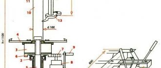
Drawings and diagrams
Before assembling the benchtop jointer, it is necessary to develop drawings. In the process of creating them, you should take into account the elements that will be part of the diagram. Standard jointers without additional features include:
- bed;
- shaft equipped with blades;
- rotating roller;
- engine;
- three tabletops;
- emphasis
In the process of developing drawings, the master must indicate the main distances between the key elements of the stationary structure. To do this, you will need to take into account the location of the motor, roller and shaft with blades. The circuit will allow you to determine how much the number of output rotor rotations will decrease if there is an increase in power, and vice versa.
Homemade surface planer from an electric planer
A wood jointing machine is made with your own hands from an electric planer; it is the main component of the tool. They plan the lumber directly with it. There is no need to worry about the performance of a hand-made mechanism - as practice shows, the quality of products does not decrease much when using such a machine, in comparison with purchased equipment.
First, you need to decide on the size of the parts that you plan to create on the future tool. In accordance with the selected dimensions, the dimensions of the machine itself are already selected. The width and height of the equipment body, the length of the pin, and the length of the thicknesser guides are determined.
What you will need to make a homemade surface planer with your own hands:
- Unoccupied manual electric planer.
- DIY drawings of a surface planer from an electric planer.
- Plywood and bars for assembling equipment casings, as material for assembling the casing.
- A small amount of free time.
Studs and guides
Then you need to correctly determine the location of the pin with which the surface planer will rise and fall. The efficiency of the future machine in working on parts directly depends on how well it is located.
For example, you can place it in the very middle of the body of the instrument, which is done quite often by inexperienced craftsmen. But this is far from the best option, since it does not provide ease of use, and also does not provide reliable and easy fixation. Ideally, in order to avoid any particular difficulties when working with the tool, you need to place the pin between the front and rear handle of the tool.
To provide the pin with the necessary mobility, a rolling bearing is installed on the top cover of the surface planer, converted from a planer. A nut is installed on the middle plate - with its help, the height of the thicknesser becomes easily adjustable, with a small step and increased accuracy.
Machine guides contribute to efficiency and precision when machining workpieces. They are made from the most ordinary wooden blocks, which do not require too much money. They should be slightly longer in length than the part for which they are intended, that is, they should not be made directly along the length of the workpieces, but leave a small margin.
Among other things, the lower plane of the marking machine must be arranged so that during operation it can be parallel to its knives. This way it will be possible to achieve maximum accuracy when processing a particular part.
Elements of a homemade tool
Electric planers were invented back in the middle of the last century and almost immediately gained popularity among builders.
They very quickly removed hand tools from the market due to high productivity.
Despite the absence of painstaking point processing, the plane allows you to perform the assigned tasks efficiently.
All modern models are quite different in appearance, but have common elements in the internal design. You can use an electric planer using one of two main methods:
- Use as a portable hand tool;
- In a stationary state, upside down (using reliable fixation on a workbench or table).
An electric planer that you can make yourself will have the same design elements as the factory models. Among them are:
- An electric motor that powers the tool;
- Protective cover (helps to save the operator’s hands from the sharp blades of the device);
- Start button;
- Knives mounted on a drum;
- Transmission mechanism (it helps transfer the rotational impulse from the shaft to the blades).
As a sole for an electric planer, it is allowed to use a flat slab (plywood, metal, boards), as well as a special workbench. The use of the second option is more preferable, since it does not require making legs for the machine. When using a stove, you will have to make a frame of sufficient height with your own hands. It must be suitable for the height of the planer operator so that it is comfortable to plane the wood.
How to work on a homemade machine
Thicknesser based on an electric planer
Working with a self-made surface planer is extremely simple. The machine pin is set at the required distance from the edge of the part, the required size is set, and the block is fixed. After this, the machine tilts slightly away from itself, as a result of which the cutting part of the pin is exposed. Then all that remains is to pull the tool towards you.
If properly executed, such a home-made machine will be almost in no way inferior in functionality to the simplest factory models of this type of electrical equipment for a home workshop.
https://youtube.com/watch?v=uE6ENWTKt0I
Construction drawings
Drawings of the frame to which all the parts of the structure being created will be attached are given below.
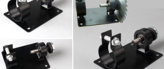
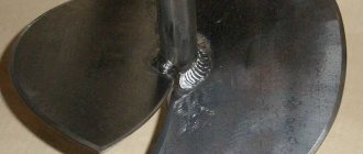
The part being processed will rest on the surface of the plate, secured with 10 bolts to a frame welded from steel angles. There is a groove cut in it for a drum with knives. To guide the workpieces and prevent their lateral movement, a square is also attached to the base plate with M8 screws.
The shaft with knives (working drum) will be attached under the table top with M6 screws. To do this, bearings will be placed at its ends, which will be fixed to the plate with special fasteners. The movement from the electric motor to the working drum will be carried out due to a belt drive.
The motor is installed inside the frame on a shelf made of two steel strips, with holes drilled in them of the appropriate diameter for the frame mounting bolts.
It should be taken into account that the slots for the engine mounts (mounting grooves) need to be made several centimeters wide (2-3) in order to be able to tension the transmission belt.
The casing, fixed with M6 screws with spring washers to the corner, covers the belt drive. The power button is installed in a convenient place on the body of the electric plane.
When working with an angle grinder and drilling, you must wear glasses - they will protect your eyes from metal shavings. In general, when working with any tool, you should follow safety rules and use personal protective equipment.
Electric planer design
Elements that will be needed for proper assembly of the structure:
Table of main parameters of electric planers.
- screws;
- bearings;
- V-belt pulley;
- steel corner;
- protective casing;
- spring washers;
- electric motor;
- steel strips;
- staples;
- switch;
- electric drill with a circle for cutting small diameters; welding device;
- knives;
- pressure plates.
The electric planer is used for processing wood up to 12 cm wide. The processing depth is 0.12 cm. The workpiece being processed will rest on a plate with a hole for a knife-type shaft. The guide square is secured to the base plate using several M8 screws with plastic heads. This element will not allow lateral displacement of the workpiece during processing.
The knife-type rotating shaft bearing supports will be attached to the plate from below; M6 screws with countersunk heads should be used as fasteners. Outside the support plate, a V-belt pulley will need to be mounted at the end of the knife-type shaft. The plate is secured with 10 screws to the body of the tool being manufactured, which is welded from a steel angle measuring 20x20x3 mm.
To protect your hands from the plane blade, you will need a hand guard.
The protective casing is secured to the housing with several M6 screws with cylinder heads. In this case, you will also need to use spring washers. The electric motor of the device being manufactured is placed inside the housing; for fastening, you will need to use two supports made of strips of steel. They have several holes with a diameter of approximately 6.5 mm, which are intended for fastening to the tool body. The elements provide several grooves that provide installation and adjustment of the placement of the electric motor for belt tension.
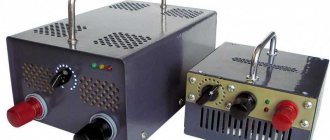
The electric motor of the device is controlled by a remote control located on the front of the case. Under the U-shaped bracket inside the remote control, you will need to place several phase-shifting capacitors, which must be fixed in parallel. The capacity of these elements is 4 µF. The switch is mounted on the outside of the console. The electric motor can be protected from direct contact with dust and chips with a special casing.
Sequence of actions for assembling the tool
The first step is to make a support plate. The most labor-intensive process is making a shaped slot in the slab, which is intended for the knives to come out. In this case, you will need to use an electric drill with a circle for cutting small diameters or make holes along the contour, and then file the slot. After preparing the holes for fasteners in the base plate, you will need to make threaded holes along them in the corners of the body of the electric plane.
Electric planer knives are mounted on the top of the tool’s rotating drum.
Before welding, you will need to attach the upper corners to the support plate with 10 screws, after which you need to attach the remaining corners of the body by welding. Next, the support plate must be dismantled, the body must be finally welded along the contour, and then the weld seams must be cleaned. Particular care must be taken to clean the plane in which the body is adjacent to the stove. It is not allowed to leave gaps, as they can provoke vibrations during operation of the electric planer. This must be taken into account.
After assembly is completed, the knife-type shaft will rotate counterclockwise - towards the feed, as viewed from the control panel. The direction must be exactly towards the feed, since the V-belt pulley cannot move in the other direction. Before starting work, the tool body must be secured without gaps. M6 screws should be used for fixation.
The knife-type shaft for making grooves must be equipped with several knives that are 12 cm wide.
You will need to install a counterweight on the back side of the shaft to eliminate imbalance and vibration.
Each knife is secured using clamping plates and M8 screws, which are screwed into the through threaded holes of the knife-type scrolling shaft.
For knives, a suitable blank is a produced metal file blade about 3 mm thick. The sharpening angle of the edge for cutting knives should be within 35-40°. In the process of shaped sharpening, it will be possible to obtain a relief base for artistic frames or platbands.
Profile slats of small thickness can be prepared by longitudinally cutting boards of greater thickness. When working with knives of small width, it is not allowed to process grooves with a depth of less than 8 mm, since the tool has insufficient strength.
Do-it-yourself thickness planer made from an electric planer
It is precisely this approach to solving most tasks for a surface planer that arise in a home workshop that we find most interesting.
First of all, this interest is based on minimal modifications to an existing tool to perform the work of expensive equipment with almost the same result.
By installing an electric planer on a platform with variable height, we get almost the same thickness planer. True, it is not the position of the work table that is regulated, but the position of the working tool in relation to the workpiece being processed, but this does not change the essence of the process. The role of the table here is played by a flat, powerful board with width limiters on the sides. They also serve as the mounting location for the main unit. But first, let's talk about him.
On the planer, we will replace the rear support plate with a homemade one made from OSB or plywood, with a thickness that ensures the same level as the front plate, which regulates the required gap (1 - 3 mm) for removing chips. Its width should correspond to the width of our improvised desktop.
On the sides of this plate, slats are screwed to attach the legs, the height of which is dictated solely by common sense. It is obvious that, based on the standard width of the plane knives of 82 mm, the thickness of the workpieces being processed should not be more than 100 mm, so the distance between the axes of the leg fastenings can be taken as 110 - 120 mm. Accordingly, their total length will range from 140 to 160 mm with a width of 35 mm and a thickness of at least 10 mm. The legs are fastened strictly at the same distance from the edge of the bar.
Installation of the assembled movable upper unit with an electric planer on the desktop is carried out locally, so that the fastening is strictly at the same level. This is done to ensure that its movement is parallel with respect to the base surface, which will ensure accurate processing of the workpiece.
The easiest way to set the height during work is by selecting slats of appropriate thickness, screwed onto the work table width limiters, or using other stands.
And the clamping of the working tool is ensured with spring ties or a harness, but for small workpieces this is not required at all. Also, in a given position, this parallel platform can be fixed with self-tapping screws.
Video of using a surface planer assembled by yourself:
Do-it-yourself electric planer repair
Almost all electric tools consist of a power cord with a plug, an off button (in most cases with a voltage regulator), an electric motor, a gearbox, an actuator and a housing.
To repair an electric planer, you will first need to determine the malfunction. If the instrument does not show any signs of life, you will need to use a multimeter or a 220 V test lamp.
To carry out repairs, the first thing you will need to do is disassemble the electric planer. It is necessary to disassemble until all current-carrying elements become accessible. Next, you will need to plug the power cable into the electrical network and check for voltage in all areas, from the cable itself to the motor brushes. If all components have been checked and voltage is supplied to the electric motor, you will need to dismantle it and carry out repairs.
Mechanical problems can be determined by visual inspection. Faulty components can be repaired, but it is recommended that they be completely replaced.
It’s not difficult to make an electric plane with your own hands; you just need to prepare all the necessary elements.
Additional Assembly Tips
The metal for the stove is cut with a grinder or jigsaw. To cut a groove, it is convenient to use an electric jigsaw, having previously drilled a hole for its file in the slab, or an electric drill with an appropriate attachment. The edges of the slot are processed with a file so as not to get injured by them later.
You can secure the metal base plate with flat head screws (so that they do not interfere with work) or by welding it. The first option is preferable because, if necessary, the electric plane is easy to disassemble.
Before installing the drum, it is recommended to check the sharpness of its knives. If it is bad, then it is better to sharpen the blades immediately, using, for example, a regular whetstone. It is necessary to constantly ensure that the cutting attachments are well secured without distortion.
The basis for making your own knives are steel plates or hacksaw blades for metal, sharpened at an angle of 30 degrees.
The sequence of making an electric plane from a grinder with the working drum placed in a vertical position is demonstrated in the videos below. It also shows possible errors when assembling a homemade product.
https://youtube.com/watch?v=SY6xchF8VzU
Another option for creating a homemade electric planer from an old, non-working model is shown step by step in the video below.
Using the made power tool, you can process boards, beams and other workpieces. An electric planer assembled with your own hands must be used in compliance with safety requirements. The parts must be fed correctly to avoid getting your fingers caught in the drum.
There are many options for homemade electric planes. They have varying degrees of complexity, as well as different functionality. In this regard, the limitations are mainly related to the technical thinking of the inventors and the parts and materials available “at hand”. If necessary, the manufactured equipment can also be equipped with automation equipment.
DIY thicknesser machine
The need to make a thicknessing machine with your own hands often arises in a situation where the use of conventional planing is clearly not enough to obtain a smooth surface for the future floor or parquet. It will not be possible to use an electric planer; the quality of the surface after an electric planer will probably be quite high, but it will obviously not be possible to get rid of the stripes that appear on the surface of the wood with each pass.
There is only one way out - try to make a thickness planer using an electric planer according to the drawings with your own hands. Thanks to the powerful bed and guide rails, the surface of the wood after processing the board with a thicknesser will be relatively uniform and flat.
Thicknesser from an electric planer
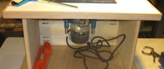
To build a full-fledged thickness planer, you first need to make a frame or table on which the tool will be mounted. The electric planer is equipped with a powerful commutator motor, which can easily cause injury, so the fastening of the homemade surface planer to the table must be strong and reliable.
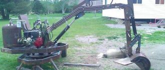
The second step is to select a plan for the layout of the surface planer. The simplest version of the device is shown in the drawing and photo.
In fact, it is necessary to make a movable platform on which the electric planer itself will be mounted. The lifting height of the tool sole on the surface being processed is adjusted using four screw-nut pairs installed on the sides of the device.
The main difficulty in operating an electric planer is correctly adjusting the lifting height of the cutting edge. In normal mode, the extension of the knife above the plane of the sole is adjusted by a screw spring-loaded handle. The amount of overhang is usually checked visually or by hand, whereas when working in the thicknesser mode, you will have to be guided only by the readings of the scale on the handle.
The only disadvantages of a planer of this type will be the small width of the surface being processed, 90-100 mm, and the actual loss of the electric planer as a hand tool. It is clearly inconvenient to disassemble and reassemble a thickness planer every time you need to remove a couple of millimeters from a nailed board.
Homemade woodworking thickness planer
Often, when carrying out carpentry work, there is a need to use a thicknesser to run a board or a board glued together from slats with a width of more than 100 mm. Planks and panels made of wood 100-140 mm can still be somewhat leveled with an ordinary hand-held electric planer, provided that the material is securely fixed on the workbench. True, it is necessary to plan diagonally in several passes, followed by processing with a manual grinder.
Cross planing of wide boards can still be used for one or two boards, but if we are talking about two dozen boards or boards, then you obviously can’t do without a homemade thickness planer.
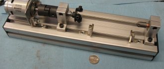
The simplest version of a surface planer is shown in the diagram.
The basis of the design is a massive steel frame welded from angle steel. An asynchronous motor with a power of 1.5-1.8 kW and a speed of at least 1200 rpm is installed in the lower part of the frame of the thicknessing machine. The motor must be mounted on a spring-loaded cushion to ensure tension on the machine drive belt and reduce vibration on the thicknessing knives.
The second most important element is a cylindrical block with slots for knives and bearing supports. You will have to buy this thicknesser part ready-made; making it yourself is almost impossible
The drum with bearings is installed directly on the machine bed after mounting the work table.
At the last stage, two pulleys are selected for the belt drive; the ratio of the diameters of the pulley groove should be in the range of 2.5-2.8. A pulley of larger diameter is mounted on the motor shaft, and a smaller one is mounted on the drum shaft. The rotation speed under load should not exceed 4 thousand rpm.
How to make a surface planer from an electric planer with your own hands?
To make a surface planer from an electric planer with your own hands, you will need a small set of metalworking and electrical processing tools, as well as a certain amount of lumber.
In general, a professional thicknesser is a special carpentry tool for mechanical processing of wood, in particular used for drawing marking design lines.
The product is also used to level the plane of specific lumber. A homemade surface planer has an electric planer as the main cutting mechanism.
► Tools and materials for making
Materials for the product:
- Plywood 15 mm thick;
- Planks and bars made of wood – 15x15, 25x25;
- Drive gears – 4 pieces;
- Bicycle chain – 1 pc.;
- Set of nuts with M14 thread;
- Set of washers;
- Screws for 25 – 100 pcs.;
- Threaded screws – 4 pcs.;
- Stands for screws – 4 pcs.
Also, to make a surface planer at home, you need a set of certain tools, in particular an electric planer and a jigsaw.
Tools:
- Electric jigsaw;
- Construction electric planer;
- Set of keys and screwdrivers;
- Screwdriver;
- Ruler and corner.
A construction electric planer will be used as the main mechanism for the product.
1. Plywood base
The base for the surface planer is made of plywood sheet with a thickness of at least 15 mm. The material is cut to the design size. The shape is a rectangle with an approximate size of 400x500 mm.
2. Fastening stands for a platform with an electric planer
The stands are also made of 15 mm thick plywood. In this case, the element is cut out from several parts and assembled on site. The unit is fastened with screws from the reverse side to the main base, to which an electric planer with a working platform will also be installed.
3. Making a platform for an electric planer
The construction electric planer is mounted on a special platform, which has a dimensional slot in the center. The technical hole must be cut with a jigsaw strictly according to the shape of the plane. The electrical appliance itself is installed using clamping strips and screws.
4. Installation of threaded screws with gears on the platform
A drive mechanism is mounted on the platform under the thicknesser, which will ensure the raising and lowering of the platform. Threaded screws are installed at the 4 corners of the base, where the electric planer is already mounted on screws.
5. Installing the platform on stands
The upper part of the surface planer with a platform and an installed plane is mounted on the main plywood stands, and fastening is carried out using screws. The electric planer cable is laid everywhere so that its braiding is not damaged during system operation.
6. Handle for controlling the platform with an electric planer
The handle on the thicknesser is mounted on one of the threaded screws. Fastening is carried out using a set of washers and nuts. To securely screw the fastening nut, you need to make a through hole on one screw.
It is important to ensure that the electric planer does not fall off its mounts.
7. Measuring bar and pointer
A measuring bar must be installed without fail to measure the material during its processing. As a bar, you can use part of a regular plastic ruler, which needs to be cut to 6-8 cm. The pointer for the thicknesser is used in the form of a regular arrow.
The finished thicknesser assembly is tested on rough material in order to further configure it. A working electric planer must be regularly maintained, in particular, it is necessary to periodically sharpen the blade and carry out cleaning.
Video: assembling a surface planer using an electric planer with your own hands.
main idea
Yes, such a homemade jointing machine, unlike serious industrial designs, has a number of disadvantages, namely:
- Cannot boast of high processing accuracy;
- The width of the workpiece is very small - only 110 mm;
- Lightweight is a disadvantage, since a heavy massive base always gives the device stability and, as a result, ease of use, which ultimately improves the quality of the result.
- Low power, limited by the power of a household electric planer;
- The body material is wood, that is, not durable;
However, it also has undeniable advantages that make it very useful for achieving certain goals and performing a number of tasks, since it has the following advantages:
- Low cost - serious jointing machines cost tens and hundreds of thousands of rubles, and the cost of this homemade jointing machine consists of the cost of the plane and materials;
- Compact and portable - it can easily be stored anywhere in the workshop and can be deployed for work in a matter of minutes.
- The simplicity of the design affects its reliability and maintainability.
- The ability to make the necessary dimensions of the machine “to suit you”, for example, you can increase the length of the work table or change the height.
Additional Assembly Tips
The metal for the stove is cut with a grinder or jigsaw. To cut a groove, it is convenient to use an electric jigsaw, having previously drilled a hole for its file in the slab, or an electric drill with an appropriate attachment. The edges of the slot are processed with a file so as not to get injured by them later.
You can secure the metal base plate with flat head screws (so that they do not interfere with work) or by welding it. The first option is preferable because, if necessary, the electric plane is easy to disassemble.
Before installing the drum, it is recommended to check the sharpness of its knives. If it is bad, then it is better to sharpen the blades immediately, using, for example, a regular whetstone. It is necessary to constantly ensure that the cutting attachments are well secured without distortion.
The basis for making your own knives are steel plates or hacksaw blades for metal, sharpened at an angle of 30 degrees.
Hacksaw blade
The sequence of making an electric plane from a grinder with the working drum placed in a vertical position is demonstrated in the videos below. It also shows possible errors when assembling a homemade product.
Another option for creating a homemade electric planer from an old, non-working model is shown step by step in the video below.
Using the made power tool, you can process boards, beams and other workpieces. An electric planer assembled with your own hands must be used in compliance with safety requirements. The parts must be fed correctly to avoid getting your fingers caught in the drum.
There are many options for homemade electric planes. They have varying degrees of complexity, as well as different functionality. In this regard, the limitations are mainly related to the technical thinking of the inventors and the parts and materials available “at hand”. If necessary, the manufactured equipment can also be equipped with automation equipment.
Additional recommendations
There are some nuances to creating an electric planer. To do this yourself, adhere to the following rules:
- The metal plate is cut with an electric jigsaw or grinder. To create a groove, first make a hole in the slab, and then drill it with a jigsaw or electric drill. Go along the edges with a file.
- Flat head screws or welding are used to secure the plate. The first method is more convenient for do-it-yourself disassembly.
- Before attaching the drum, check the blades for sharpness. If necessary, they are sharpened on a stone.
- If you make knives yourself, then use steel plates or hacksaw blades for metal sharpened at 30 degrees.
After completing the assembly of the tool, it can be used on boards, beams and other objects. Be sure to follow safety precautions for planing. The parts are fed carefully so that your fingers do not touch the drum.
How to extend the life of an electric planer
An electric plane is one of the main tools for woodworking. Properly configured, it is an indispensable assistant in the hands of a carpenter. If, over time, the tool settings have gone wrong, or you don’t know how to prepare the electric planer for work, then it is advisable to get specialized advice, which we are ready to offer in this material. Otherwise, all the work when working with an unregulated plane will go down the drain, and there will be little pleasure from such miserable work.
Like any tool, the plane must be properly adjusted before work. And an electric plane imposes even more stringent adjustment requirements than hand tools. Therefore, the following steps should be carried out before each work with such equipment.
The only warning before inspecting the tool is to follow the safety tips. So the cutting parts of the plane must be treated very carefully. After all, due to the fact that the cutters of this tool are extremely sharp, you can cut yourself on them even when the equipment is turned off, not to mention when the equipment is running. Otherwise, such equipment should be treated like any other power tool.
Required materials and tools
Let's consider the manufacture of the simplest design, designed for a planing depth of up to 1.2 mm and a width of processed wooden workpieces of up to 120 mm. To assemble such an electric plane with your own hands, you will need the following materials and parts:
- bearings;
- steel strips;
- pressure plates;
- M6 and M8 screws with nuts;
- spring washers;
- metal corners (20x20x3 mm);
- staples;
- sheet of plywood (10 mm) or metal (3-5 mm thick);
- belt drive pulleys installed on the shaft of the electric motor and drum;
- a drum (with one or two knives) from an old planer or electric planer, on which you can change cutting attachments;
- a working electric motor from a grinder, an old electric plane or a planer;
- belt;
- button (switch) to turn the electric planer on and off;
- wires and cord with plug;
- residual current device (RCD);
- capacitors (if the electric motor used is three-phase).
Installing a separate RCD for an electric plane in the panel (even directly on the machine) will increase electrical safety when working with equipment. Protection is selected according to the power of the working engine. The cord and wires must be of a suitable cross-section, taking into account the power of the installed electric motor.
Phase shifting capacitors must be connected in parallel. In this case, the required total capacity is determined by the power of the installed electric motor: approximately 100 μF per 1 kW. Capacitors must be designed for mains voltage.
To implement the project you will need the following tools:
- several wrenches designed to tighten the nuts on the bolts;
- roulette;
- building level;
- marker or pencil;
- welding machine with electrodes;
- an electric drill with drills and a circle of small diameter intended for cutting;
- a jigsaw with files for it for wood and metal or hand saws for a similar purpose;
- angle grinder complete with wheels for cutting metal.
- https://verstakdoma.ru/stati/instrument/samodelny/rubanok-svoimi-rukami/
- https://tehnika.expert/dlya-remonta/elektrorubanok/delaem-instrument-svoimi-rukami.html
- https://drevogid.com/instrumenty/ruchnoj-rubanok.html
- https://zdesinstrument.ru/ruchnoj-rubanok/
- https://stankiexpert.ru/ehlektroinstrument/rubanok-ruchnojj.html
Tools
0 votes
+
Vote for!
—
Vote against!
For many people, working with wood brings great pleasure. It’s nice to make a table for the veranda with your own hands, assemble a garden bench or replace a leaky board. Only the joys of creativity are overshadowed by routine physical work, which electric planes are designed to combat. Anyone, even a beginner, can work with a manual electric planer.
Content:
- The purpose of the electric planer
- Electric planer design
- Rotating drum
- Electric planer sole
- Electrical part
- Tool handles
- Knife protection
- Chip ejection
- Accessories for electric planer
- Specifications
- Making an electric planer with your own hands
The purpose of the electric planer
The plane is the oldest tool for wood processing after the axe. Any professional treats him with special respect. The painstaking work of the designers and electricity made the plane even more perfect and efficient. Thus, modern electric planers outwardly resemble their mechanical counterparts, but new designs are several times more productive than manual labor.
The electric planer is intended for processing wood, reducing the thickness of wood products, preliminary planing, fitting, processing boards on a bed, beveling edges and creating an extended recess of various shapes in products (chamfer, quarter, tongue). All this is called by one term - planing. This tool is not suitable for processing a larger area, but for small volumes it makes the work easier for a frequent repairman or a professional when handling wood.
The main function of a planer is to level a wooden surface that has previously been roughly processed. After leveling the product with a plane, all irregularities and defects disappear from the surface, and it becomes extremely smooth. Finishing wood is usually done with a sanding plane. An electric plane can also be used to make a chamfer or groove in a workpiece.
Electric planer design
The design of an electric planer is quite simple. Let's take a closer look at the electric planer circuit and its constituent elements.
Rotating drum
In the body of the electric planer, on the base plate, there is the main working element - a rotating drum on which the knives are attached. As a rule, in the “knife drum” there are two, less often three or one, knives, which cut the upper surface of the wood being planed. The knife shaft is much more technologically advanced than a conventional cutter, and the power of the tool allows you to work without any additional effort.
Knives are made from tungsten, hardened steel or carbide. According to the number of knives that are fixed on the drum, electric planers are “two-legged” and “one-legged.” The first type of tool works only with precise alignment, otherwise only one knife will work, the second is simple and productive. Electric planers with a knife mounted obliquely on the drum are capable of making a specific “spiral” cut for high-quality planing of the board.
Over time, knives wear out. There are reusable knives that need to be sharpened, or disposable knives that need to be changed. The frequency of these procedures is determined largely by operational loads: the type of wooden surface and the time of their processing. To remove the knife, slightly loosen the bolts that hold the knife holders in place. They are easily removed from the drum grooves. After sharpening, the knives are put in place, aligned in height with each other, as in the video about the electric planer.
Straight carbide knives, thanks to the presence of a centering groove, are easily mounted in their place in holders, which are in turn inserted into the grooves of the drum. Sharpened steel knives require more careful alignment in height.
Electric planer sole
The sole of the electric planer is made of cast aluminum and is divided into 2 parts relative to the drum - front and rear. The rear part is fixed, and the height of the front part, which can move on untreated wood, can be adjusted using a knob or button. The position of the front part primarily determines the depth of planing or, in other words, the thickness of the chips.
The sole influences the stability of the electric planer. In any case, this element should not interfere with work and be smooth. The soles, which are produced by some manufacturers, have several V-shaped grooves in their surface, which are needed for chamfering the corners of the workpiece.
Electrical part
The rotating drum is connected to an electric motor using a drive belt, which is responsible for transmitting the rotational motion. The drive belt needs to be changed from time to time. But this task is not at all troublesome, because belts are sold in all tool stores. You can remove the old belt yourself. To facilitate this operation, the manufacturers made the protective cover removable.
The electric motor has a power of 580 - 900 W, its rotation speed reaches 1000 rpm. The quality of the treated surface largely depends on the engine power. The electric planer contains a switch with a lock and a cord with a plug, as well as various electronic units: changing or stabilizing speed, soft start, drum balancing, overload protection and even an electronic brake.
Tool handles
To move along the working surface of the electric planer, two handles are used. The rear one allows you to push the tool; there is a start/stop trigger with a double safety system. Using the front additional handle, they only direct the movement of the electric planer; the same handle allows you to work “in a big way.” If you press firmly on the front handle, you can remove a large layer of wood at the end of the material being processed.
Since the adjustment handle is sometimes used as a second handle, it is often made with internal notches so that it can be raised when switching, otherwise it is possible to accidentally knock down the specified chip thickness during operation. A handle without such notches can adjust this parameter on the go, but this does not allow you to get rid of unwanted switching.
The switching step is usually 0.1 millimeter, but each electric planer has its own differences. The cutting depth can be set by turning the knob. At the same time, the front part of the sole lowers or rises, opening the drum with knives less or more.
Knife protection
Two types of protective devices protect the surface being processed and the fingers from the bottom and sides from contact with the knives. At the bottom of the sole there is a leg, like in the photo of an electric plane, which is automatically thrown out, slightly lifting the back of the sole. The movable safety leg will fold back when the electric plane is not working and protect the workpiece from contact with the knives. You can also place the plane on its side, with the drive belt cover down.
A protective plate on the side on a spring covers the edge of the knife drum and is raised as far as the plane will go deeper into the wood when selecting a quarter. The side edge of the knife drum, which allows you to select a quarter, is hidden under a rotating plate.
Chip ejection
The procedure of direct ejection of chips relieves the electric plane from clogging and occurs in three ways. In the first case, no technical frills are required; the shavings will scatter throughout the room, but the working surface will not become clogged.
The ability to direct the ejection bell in some models makes it easier to remove chips; this is where the second option for ejecting chips lies. The bag holds a large volume of shavings without being too bulky. If you need a bag, you should ask whether it is included in the set and whether it is possible to purchase it in addition.
A good solution to the problem is to connect it to a vacuum cleaner using a corrugated hose, but it will not completely rid you of debris. Depending on the location of the operating electric plane, it is convenient to direct the ejection of chips in a certain direction.
To do this, you just need to switch the key to the desired position. The method is simple, but is inconvenient in some cases, because the hose and cord limit the maneuverability of the structure.
Accessories for electric planer
There are many different accessories for the tool, regardless of the price of electric planers. For example, wavy knives made of hardened steel, of different overall dimensions, which are used for roughing, as well as equipment that allows you to install a plane motionless and turn it into a planer and an automatic jointer at the same time.
The side stop, together with the depth gauge, is able to accurately set the width and thickness of the chips being removed. To cut a corner, it is customary to tilt some stops from 0 to 45 degrees. When planing a thin edge, the side stop will help give the plane the necessary balance. Of all the possible accessories described above, they must be included in the kit.
Specifications
The power of an electric planer is 0.4 - 2 kW. An electric plane with a power of 500 - 900 W is suitable for use at home and for DIY repairs. For simple and short-term work, a household-grade electric plane or a homemade low-power electric plane is suitable. And for real masters, you will only need a professional powerful tool.
The rotation speed of the cutter can influence the surface finish and is 10 - 18 thousand revolutions per minute. In some models, the rotation speed can be changed. It can also be maintained at a constant level by electronics, which is very convenient when working with hardwood.
The planing width is 82 millimeters or more. This indicator is important when you spend most of your time processing boards. For many companies, the planing width of wood usually does not exceed 82 mm, but there are those on the market that have increased the planing width to approximately 102 millimeters.
You can set the planing depth within 0 - 4 millimeters. It can be smooth and step-by-step. The cutting depth of the edge ranges from 0 to 25 millimeters, respectively.
Making an electric planer with your own hands
The electric plane that you will be making is designed to process wood in one pass, which has a width of up to 120 millimeters and a cutting depth of up to 1.2 millimeters. The workpiece will rest on a plate with a hole for the knife shaft. The guide square is mounted on the base plate using 2 M8 screws that have plastic heads; it prevents lateral movement of the product during processing.
The bearing supports of the blade rotating shaft are attached to the base plate from below with M6 screws that have countersunk heads. Outside the base plate, it is customary to install a V-belt pulley at the end of the cutter shaft. The plate is secured with 10 screws to the body of the electric planer, which is welded from a steel angle measuring 20 by 20 by 3 millimeters.
The safety casing is connected to the body with three M6 cylindrical head screws above the V-belt drive through spring washers. The electric motor of the tool is located inside the housing and is connected to it using 2 supports in the form of steel strips. They have 2 holes with a diameter of approximately 6.5 millimeters, which are intended for mounting on the body of the electric planer with your own hands, as well as 2 grooves each, allowing for installation and adjustment of the position of the electric motor for belt tension.
The electric motor of the device is controlled from a remote control located on the front of the body. Under the U-shaped bracket inside the remote control there are 2 phase-shifting capacitors, which are mounted in parallel and have a capacity of 4 µF. The switch is mounted externally on the remote control. The motor is protected from direct contact with dust and chips by a casing.
First of all, make the base plate. The most labor-intensive operation is considered to be making a shaped slot in the plate, which is intended for the knives to come out. For this purpose, use an electric drill with a cutting wheel of small diameter or drill along the contour of the hole, and then file the slot. After drilling the mounting holes in the base plate, threaded holes are made along them in the 4 upper corners of the electric planer body.
Before welding, the upper corners are attached to the base plate with 10 screws, and the remaining corners of the body are secured to them by welding. Then the base plate is removed, and the body is finally welded along the contour, cleaning the welds. Particular care is taken to clean the plane in which the housing is adjacent to the base plate. In this case, gaps are unacceptable, because they provoke vibration during operation of the electric planer. Keep this in mind before making your own electric planer.
After completing assembly, make sure that the cutter shaft will rotate counterclockwise - in the direction of feed, as measured from the control panel. This feature is of great importance, because the method of securing the V-belt pulley to the knife shaft does not allow it to move in the opposite direction. Before starting work, secure the plane body without gaps with 4 M6 screws.
The knife shaft for cutting grooves is equipped with 2 knives that have a width of 120 millimeters, or one knife. In the latter case, a counterweight is installed on the opposite side of the shaft to eliminate imbalance and vibration. Each knife is secured using pressure plates and 3 M8 screws, which are screwed into the through threaded holes of the rotating knife shaft.
For knives, the most affordable workpiece is the spent blade of hacksaw saws for metal, which has a thickness of about 3 millimeters. The sharpening angle of the cutting edge of knives should be within 30 - 40 degrees. With figured sharpening, you can get a relief surface for artistic frames or platbands.
Narrow and thin profile slats, which are less than 10 millimeters wide, can be prepared by longitudinally cutting a wider board. When working with narrow knives (less than 12 millimeters), it is not recommended to process grooves that have a depth of 8 millimeters, due to the lack of strength of the tool.
Now you know how to make an electric planer, all that remains is to find out how to properly sharpen the knives for it. We'll talk about this in the next article.
A budget option for a homemade surface planer
This is the simplest method of using an electric planer as a surface planer. Of course, it would hardly occur to anyone to call this design a thickness planer, but in terms of the function it performs, this is exactly what it is.
We deliberately selected an option for wide blanks. Indeed, in this form it performs work that most industrial thicknessing machines cannot do precisely because of the width of the material being processed, and in our case it is limited only by the length of your hands.
Of course, we cannot recommend such a barbaric attachment of an electric plane - a rather expensive tool - to a moving platform. Much more interesting is the option of securing it, described in the previous section of the article, but using a wider platform and moving the slats along the width, and not along the axis of the tool
In this case, the danger of damaging anything important inside the plane body is reduced to zero.
In the example given, a glued assembly of wooden slats of various sizes and even types of wood is processed.
Height adjustment is made by installing calibrated bars on the sides of the work table, two sets of which will allow you to process an unlimited number of workpieces on both sides to a given thickness.
Planer device
During the evolution of the plane, quite a lot of its varieties have appeared, which can not only process the planes of wood, but also be used for figured cutting. To enjoy manual labor, you need to be able to choose the right plane, and then you will get real works of art from an ordinary piece of wood.
Modern planes can be divided into wooden and metal models. Each of them has its own advantages and disadvantages, but in terms of design, the instruments are similar, like twin brothers.
A standard plane consists of the following parts:
- sole, also known as body;
- cutter;
- wedge;
- slot for chip exit;
- cutter clamp;
- cutting depth regulator;
- horn - front handle;
- emphasis - rear handle.
The key element of the design is the cutter - this is a cutting tool made in the form of a pointed plate.
The blade is positioned at a given angle to the surface being processed. Thanks to the regulator, the knife extends to a certain distance, which allows you to finely adjust the depth of cut and the thickness of chip removal. In factory models, the blade sharpening angle is standard, but professional carpenters change it depending on the type of wood being processed.
The handles also play a certain role. The front one, called the horn, performs a guiding function and usually has a curved shape that provides a better grip on the hand. The rear one is a stop, thanks to which the force necessary for work is created.
With the sole, which can be wooden or metal, everything is not so simple. The main criterion for this structural element is a perfectly flat surface.
If this requirement is not met, it will be difficult to use a hand plane, and you can simply forget about planing accuracy. Taking these nuances into account, a metal sole looks preferable: it is made according to a template, so a priori it has the correct geometry. However, mistakes made by the manufacturer during casting reduce these advantages to zero. Moreover, the metal is susceptible to corrosive changes.
A wooden sole is lighter, and if deformed, you can straighten it yourself, breathing a second life into the plane. However, wood is not a durable material; it is subject to mechanical wear and loses its original properties when exposed to moisture or high temperatures for a long time.
Despite the standard design, there are more than 10 types of planes, and each tool performs a specific function when processing parts. Let's take a closer look at these products.
Machine parts
A homemade jointer is represented by a combination of various units that are connected together. The manufacture of the jointer must be carried out taking into account the information below:
- Base. It is represented by the lower part, on which various nodes are based.
- Side wall. It acts as a load-bearing element to which various components are attached for mounting.
- The table is rear or fixed. This element is attached to the side wall and forms the plane of movement of the workpiece.
- Front table. Often this element can change its height. A special mechanism is created for this.
- Side support. It is mounted on the back table; its main purpose is to direct the movement of the workpiece.
- Spacer corners. They are used to strengthen the structure and increase its stability.
- Electric planer. An electric planer is used as a basis in the manufacture of the structure.
This mechanism is characterized by a fairly simple design. To connect individual units, various fasteners are used.
Making a homemade jointing machine from an electric planer
You can make a jointer from an electric planer with your own hands, even if you don’t have the required skills.
In this case, attention should be paid to all components, since the main operational characteristics largely depend on the quality of each. You can make a jointer from an electric planer with your own hands, taking into account the following points:
The project is downloaded on the Internet or created independently, it all depends on the specific case. The next step is to choose a suitable electric planer
It is characterized by a large number of features, for example, power or type of blade installed. When creating a machine from a plane, you need to pay attention to ensuring that it is stable. Otherwise, the quality of processing is significantly different.
You also often make a stand for a plane with your own hands. It significantly improves the quality of the processing performed.
Manufacturing algorithm
To assemble the device with your own hands, adhere to the established plan. The sequence of actions looks like this:
- To create a support, a rectangle is cut out of metal. Markings are made on it for the drum and mounting holes;
- Steel corners are screwed in on all sides of the slab with bolts and then welded;
- From the remaining corners, cut out 4 legs for the plane;
- The resulting racks are welded to the corners of the slab;
- A rack for the motor is assembled from steel strips. It is attached through holes in the support;
- The seams are being cleaned;
- The plate is removed;
- The upper parts of the corners are welded so that there is no space between them;
- The resulting seams are cleaned with a grinder or file;
- The stove is put in place;
- Under the slot, a drum and bearings are placed on clamps or brackets;
- The engine is secured in the desired position (the shaft must protrude);
- Pulleys are installed on the shaft and drum;
- A belt drive is installed;
- The engine is installed in such a way that the belt tension is sufficient;
- A plywood or tin casing is created. It is attached with screws to the corners so as to cover the belt and motor;
- The case is covered with plywood at the location where the start button is installed, then the button itself is installed;
- A capacitor is installed if necessary;
- Assembling an electrical circuit with your own hands (power cable, button, machine, capacitors);
- The first test run of the device takes place.
After starting work, the master pays attention to the direction of rotation of the drum. It should be carried out in the same direction from which the wooden blanks for planing are fed
Necessary materials
As an example, we take a simple plane that allows you to set the depth to 1.2 mm, and use boards with a width of up to 12 cm. To create a do-it-yourself electric plane with these characteristics, use the items below:
- Steel sheets (or strips);
- Bearings;
- Spring washers;
- Pressure plates;
- Screws with nuts (M6 and M8);
- Staples;
- Metal corners (20x20x3mm);
- Plywood (1 cm thick) or sheet metal (2-3 mm);
- Belt pulleys for installation on the engine and drum;
- Electric motor from a plane, planer or grinder;
- Belt;
- Drum from an electric planer or planer with the ability to replace attachments;
- Cables (wires) and plug;
- Start button;
- Capacitors (for three-phase motor);
- Device for protective shutdown (RCD).
The presence of an RCD will help to avoid injury and breakdown of the electric planer during operation. The cross-section of the cords should be selected in accordance with the power of the engine that will be installed. Protection is selected according to motor power.
The tools that will help you create an electric planer with your own hands are:
- Wrenches for tightening nuts of the appropriate size;
- Level;
- Roulette or measuring tape;
- Pencil or marker for marking;
- Welding machine with electrodes;
- Electric drill;
- Drill bits and cutting circle for drill;
- Grinding machine with wheels for cutting metal (angular);
- Electric jigsaw;
- Jigsaw files (for metal and wood), or a hand saw.