Examples of using rivets and contact pins.
Small rivets may be needed when assembling amateur designs.
And contact pins for connecting cables to the printed circuit board.
Also, based on the contact pins, you can make a very convenient breadboard for reusable prototyping of radio circuits.
Additional tools
What is not in the set, but will or may be needed:
1. Tweezers. We took a manicure. 2. 9V Krona battery 3. Phillips screwdriver - one of the circuits has a terminal. Tighten the wires in it using a clockwise Phillips screwdriver. 4. A “third hand” soldering device - this is something you can do without, although it is constantly mentioned in the instructions and brochure. Of course, it would be more convenient with it, but if you simply assemble all the parts on the board and then turn it over, then both boards included in the set will be relatively stable and soldering will be, in principle, convenient and without additional devices. 5. Magnifying glass 6. Desalter pump 7. Goggles and respirator 8. Soldering iron stand 9. Fan/exhaust hood
Of this entire list, it will be very difficult only without the first two points. This time our stand for the soldering iron was the robot from the previous post. The rest for mounting two small boards would really be superfluous.
But it would be useful to remind you that when soldering, tin vapors are released, which are not very beneficial for health. Actually soldering the two circuits included in the kit took me no more than 10 minutes and I didn’t feel bad. However, a small fan to push the smoke away, or at least an open window, is standard and very good practice. In addition, you should wash your hands after soldering. You also need to take care of your eyes - the leg of a part bitten off by wire cutters may fly off, or a drop of hot tin may fly off during the soldering process (although it didn’t fly off for us). Therefore, wear safety glasses. Take care of yourself!
How to make a rivet?
So, in order to make a rivet with a countersunk head from copper or aluminum wire, we need two steel bars of a suitable size.
In a good way, before drilling out a socket for a rivet, it would be good to fix the position of these bars with pins. But, if you need to make just a few specific rivets or flare a single metal tube, then the pins can be neglected. If you still want to assemble the stamp halves on pins, they can be made, for example, from spring steel or from the shanks of broken drills.
The steel bars must be tightly compressed in a vice or clamp and the future hole must be punched.
To obtain a more accurate hole shape, it is better to drill it in two stages. First, you should drill a centering hole with a drill having a diameter one and a half to two times smaller than the diameter of the wire.
And then select a second drill so that its diameter is 0.1 mm less than the diameter of the wire or more if the wire is very thick. In other words, you need to ensure tension between the hole and the wire.
Finally, you need to drill out a cavity in the stamp to form the countersunk head of the rivet.
In order for the countersunk head to have the correct shape, the cutting edges of the drill used must be located at an angle of 90 degrees.
If we now insert the end of the wire between the halves of our stamp and tightly clamp the stamp in a vice, the wire will be securely fixed in the matrix. When using a clamp instead of a vice, the stamp must be mounted on some massive steel plate.
In order to get a neat flat cut when cutting the end of the wire, this operation must be done with “correct” side cutters.
You can shape the flat surface of the cap using any flat mandrel and a hammer.
To form a hemispherical rivet head, the stamp must be turned over, and the protruding part of the wire must be flared using a special mandrel.
A mandrel with a recess in the form of a hemisphere can be purchased at a tool store, or you can make it yourself. To make a hemispherical recess, a hole is first drilled in the mandrel using a drill sharpened to a pattern, and then a steel ball from a ball bearing is pressed into the resulting recess.
Tips for working with soldered boards
Some useful tips to help you assemble the board correctly:
- Immediately cut the board to the required size. For this, ordinary scissors, a cutter, or a hacksaw are suitable. You can even just break it along the holes, but then clean the edges.
- If you are not going to use the board right now, then do not touch the areas with foil with your hands again. Hands may be wet, which will lead to surface corrosion and poor contact.
- If oxides or dirt occur, clean them with fine sandpaper or a regular eraser.
- Radio elements are installed on the side where there are no foil strips. The leads are inserted into the holes and soldered on the reverse side.
- The blue color of the conductive paths indicates the “minus” of the circuit, the red “plus”, and green is used at your discretion. The tracks are marked on the same side where the foil is located.
- The most important positioning of parts occurs in a vertical position, since in this case an error will lead to an incorrectly assembled chain.
Please note that both types of breadboards may have slots on the sides. This is necessary for those who assemble a large device consisting of several modules. The grooves allow you to assemble one large board from several small ones.
How to make a contact pin?
To stamp contact pins, you need to make a stamp similar to that described above, with the only difference that instead of a conical-shaped recess, you will need to drill a cylindrical recess. To do this, you can sharpen the drill for a trunnion drill or simply ensure a sufficiently obtuse angle between the cutting edges.
To form a support collar on the body of the future contact pin, you will need another mandrel-punch. The diameter of the hole drilled in it must be such that the wire enters the hole freely, but with a minimum gap. The hole itself should have a slight taper to prevent the copper wire from jamming in the punch hole. The depth of the hole is chosen so that, in the future, the contact can be riveted into the printed circuit board.
During stamping, the upper part of the wire should be lubricated with CIATIM lubricant or a thick paste made from soap and water. This will prevent the wire from jamming in the mandrel hole.
This is what the matrix for stamping contact pins looks like. In the picture you can also see a contact pin extruded from copper wire.
And this is a mandrel-punch for forming a collar of a contact pin with a pin inserted into it.
If you intend to stamp a large number of contact pins, then it is advisable to harden all parts of the stamp.
Connecting wires
If the board does not come with connecting wires, you can use regular ones. They must be insulated, then you can safely assemble any circuit diagram.
The wires most often used for such purposes are those used in security alarms. Any single-core or stranded wires will also work. The main thing is that it is convenient to work with them. All you need to do is cut the wire into pieces of the required length and strip their ends of insulation. It is advisable to tin all ends.
How to flare a contact pin in a breadboard or printed circuit board?
The finished contact pins are riveted into the printed circuit board using a lower mandrel, which is a steel pin with a hole slightly larger than the diameter of the contact pin. This mandrel is fixed in a vice or screwed into some kind of massive base. Please note that one side of this mandrel is ground off so that pins located close to each other can be riveted.
Flaring of a contact pin in a printed circuit board can be done either with a regular hammer or with a hemispherical mandrel of the appropriate diameter.
The video shows how to use the die and how to flare the contact pins in the PCB.
July 4, 2014 (11:39) in Technology
Wrap installation. Homemade development board
In the last article we looked at the technology of installation by wrapping. But practice is the criterion of truth. In addition, DIHALT asked a specific question about what to do with the details? It is clear that the parts are placed on the board on one side, and all connections occur on the other side (it seems logical, but how?). There are ready-made boards for wrap-around installation, but they are very expensive. In this article I will show my solution for how to wire-frame prototyping on a board that I made myself in just a couple of hours.
First difficult steps
At the end of the first part, I talked about the practical application and problems I encountered.
Now I am developing a synthesizer project on FPGA and am in the process of constant experiments, so the circuitry is constantly changing. Reconnections are constantly required. If inside the FPGA it is enough to transfer signals to other pins, then on the board everything does not happen so quickly. It was in order to increase the speed of changing the circuit, its reliability and resistance to repeated alterations, that I took up installation by wrapping. But not everything is so smooth. My project consists of two boards: a board on which the FPGA chip is located and an expansion board for it - a synthesizer. The boards are connected via a 40-pin connector using a ribbon cable. Then I made the entire circuit on the expansion board surface-mounted. That is, the wires were soldered directly to the connector pins. And in order to switch to wire-wrap installation, I need to bring these 40 lines to the side of the board where the pins will be. There, for example, I output, say, 8 resistors of 10 KOhm each. I do as I decided earlier. I insert the stands into the board. I solder radio elements to the racks on top. In the case of the connector, I had to solder the wires. Everything turned out very badly: it took a long time, it was not reliable, it was not convenient, it was not beautiful. In addition, the racks were very poorly tinned and it was very difficult to solder to them.
On top are pins for switching to Wire Wrap. There is a connector under them. And 20 bagels - wire. Below are 8 resistors soldered to the posts
The same - on the other side: the top row is the connector posts, below are two rows of the posts to which resistors are soldered
Having spent 3 hours and done only half the work on just the connector, and somehow soldered 8 resistors, I went to bed with sad thoughts.
There were two thoughts: 1) I’m not installing the elements correctly 2) I need to solve something with the fact that the racks are not tinned well
And before going to bed, I had an epiphany!
Board concept
Ready-made Wire Wrap boards are usually made using this principle.
On one side the elements are installed
On the other hand, it all comes out as pins
Long pins. And besides the pins, there is nothing at all on the other side.
And why don't I do that? Why do I thread the racks through, do not secure them in any way, and solder the radio elements onto the racks?
This is nonsense! The radio elements must be soldered onto the breadboard as usual, and the pins must be brought out to the other side, where there are no copper conductors!
All that remains is to solve the problem with tinning. The issue was resolved with the help of F38N flux. I don’t even understand how I lived before without him!
Let's do it!
We take curved Chinese boards:
Racks
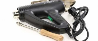
Soldering iron (I have a 12-volt car one with a charger from the same place), a third hand, my favorite solder is POS-61 1.5mm two meters, and the discovery of this fall is F38N, there is also a thin tube into which I took acid and applied it to racks.
We saw off the excess from the board, sand it, and degrease it. We tin the racks. We install it on the board and solder it. Thanks to the flux and POS-61 in the coil, soldering was a pleasure! Fast and beautiful.
At the end of the board I make two strips of 20 each from racks. This is a connector for connecting to the FPGA board. There are also two wires - power.
The rest of the installation on the board serves solely for prototyping the circuit I need.
From the printed circuit board side we will solder discrete elements: microcircuits, resistors, capacitors and connect them there to one of the racks. Better yet, solder the sockets and quickly insert all the elements into them
And on the other hand, connect the elements by wrapping (the two lines on the right are power supply).
IMPORTANT POINT!
When switching to installation by wrapping, you need to switch your thinking a little and start doing installation by wrapping. Avoid surface mounting and, if possible, soldering. I couldn't do it the first time. And now, when I made a new board, I almost started making the same mistakes again. Here's an example: you need to transfer all 40 lines from the input connector to the first line of racks. What am I going to do? Certainly! Solder the wire from the connector to the first line. But this is a mistake. There is no need to do this. In general, there is no need to re-roll all 40 lines. You only need those that are required in this scheme (1)
. And instead of soldering, we can use wire-wrap installation. The stands are large, after installing the cable there is enough space under it to wind the wire (2).
(A few days later).
This is what the board looks like now. During these days she changed several times, but all the changes were easy and quick. View from the installation side:
View from the installation side of the elements (sorry it’s so colorful):
Conclusion.
This layout method suits me and I will use it in the future. Try it!
The first damn thing is lumpy or immediately troubleshooting
There is an anecdote: a man bought an airplane and a magazine with a description of “How to make a loop.” Following the instructions, I boarded the plane, took off, started doing a loop - everything worked out. He turns the page, and there: “... read the way out of the dead loop in the next issue.”
We can talk a lot about the culture of soldering and the fact that it is an entire art. One thing will remain unchanged: if you do something for the first time and according to a book, then at first it may not work. Here is our first board, the “Chameleon” set, or rather what came out of it. What mistakes were made?
1. The soldering technology is broken, as a result - unsoldered contacts, which are better to be desoldered and soldered again (without mixing up the polarity!) 2. The operating technology is broken: each part was soldered in turn. Below you will see how much more profitable in this regard it is to listen to the instructions and first assemble all the parts, and then fasten them.
Result:
the parts fit beautifully together, but out of three diode chains, only one lit up in the end.
Possible Solution:
Unsolder all the parts and solder them again.
Positive point:
can always be found. In this case, we don’t have “parasitic bridges” anywhere. True, removing them is quite simple in any case: just hold the soldering iron tip and separate the contacts that are soldered together.
Solder!
So, the first circuit did not work out for us due to a violation of the soldering technology, so let’s immediately discuss this simple and actually pleasant point.
The brochure quite clearly shows and tells how to solder, but, unfortunately, it didn’t help me much, because it says “how to”, but I would like to understand the technique itself.
Perhaps the best recommendation I could find was in this post. I will quote it in its entirety:
It's all about the process. You need to do this:
- The part is inserted into the board and must be secured (you won't have a second hand to hold).
- Take a soldering iron in one hand, and a wire of solder in the other (it’s convenient if it’s in a special dispenser, like in the picture).
- You DO NOT need to take solder to the soldering iron.
- Touch the tip of the soldering iron to the soldering area and heat it. Usually it's 3-4 seconds. (actually 1-2 s. - approx. A.Ch.)
- Then, without removing the soldering iron, with your other hand, touch the tip of the solder wire with flux to the soldering area. In reality, at this point all three parts come into contact at once: the soldering element and its hole on the board, the soldering iron and the solder. After a second, “pshhhhhh” happens, the tip of the solder wire melts (and a little flux flows out of it) and the required amount of it goes to the soldering site. After a second, you can remove the soldering iron with solder and blow.
Additionally, I can recommend an illustrated comic translated by habra user atarity.
Also, from time to time carbon deposits form on the soldering iron tip and need to be cleaned. For this, the industry uses special cellulose sponges, always moistened with water. In our case, carbon deposits can be removed simply by shaking it off mechanically - for example, with the blunt side of a knife.