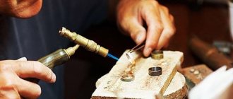
The ability to solder in modern life, saturated with electrical appliances and electronics, is just as necessary as the ability to use a screwdriver and a plunger. There are many methods for soldering metals, but first of all you need to know how to solder with a soldering iron, although other methods are feasible and may also be needed at home. This article is intended to help those who want to master the technology of manual soldering work.
Note: we do not touch on soldering propylene and other plastics here. This, in fact, is not soldering - the technical process does not contain the necessary components of soldering work, solder and flux. Technologically, soldering plastics is closer to low-temperature resistance welding. The same applies to cold soldering - joining parts with conductive glue.
Soldering metals with solder is a rather complex physical and chemical process, but in operation it comes down to fairly simple techniques and operations. In order to solder correctly, without wandering into the wilds of theory, the rules for performing soldering work must be followed exactly. This is especially true for the choice of soldering method, solder and flux, depending on the type of parts to be connected and the requirements for the soldered joint. The main part of the presented material is devoted to the description of these and other details, without which a strong joint cannot be obtained.
Note: If you want to quickly solder something, you can watch a detailed video tutorial on the basics of soldering for beginners below. But keep in mind that it will not replace what follows in the text. In soldering work, the rule “do this, it will turn out this way” does not always apply. And in an established production, it happens that you have to rack your brains - what to do if it doesn’t work out right? Or, what needs to be done to make it work like this, if there is no way to do it this way.
What is soldering?
Do-it-yourself soldering at home comes down to the following technological operations:
- The soldered surfaces are cleaned of dirt, corrosion crusts, etc.
- Clean until shiny, i.e. until there are no visible traces of oxides;
- They are coated with flux - a substance that removes oxide residues and prevents oxidation of surfaces in the further process. For fluxing under tinning, it is preferable to use flux pastes rather than liquid or solid fluxes;
- Then the surfaces are tinned - molten solder (an alloy specially designed for soldering) is applied to them, while it spreads into a thin film and chemically combines with the base metal;
- The parts are pre-connected mechanically: by twisting, compression with tweezers, pliers, in a vice, clamp, etc.
- Flux is also applied to prevent oxidation of the solder under heat;
- While heating, more solder (perhaps a different one) is applied until a junction of the specified quality is obtained;
- If soldering was carried out with a soldering iron with a tinned tip (see below), upon completion it is cleaned and coated with inactive flux. To ensure high-quality soldering, a regular soldering iron must be stored with a fluxed tip!
Next, we will take a closer look at the key operations that you should pay special attention to in order to learn how to solder properly.
Necessary Retreat
In the comments on the topic of soldering, the topic is widely discussed: what is the correct way to tin or tin? According to the rules of the Russian technical language - tin, as in other word forms from “tin”; fornication has nothing to do with it. But it’s better, if possible, to do without consoles at all, because in the roots of word forms, “d” is often changed to “zh” (pudding), and then a parasitic association with a puddle is possible. What is tinning - dipping into a puddle? It is necessary to tinker. “Soldering” instead of “soldering” is clearly unacceptable, because these words have completely different meanings. Just like “solder” instead of “solder”. Fast ice is a strip of coastal ice formed when bodies of water freeze. And adhesions are an undesirable consequence of surgery. The place where parts are connected by soldering is a junction.
Note: in the northern dialects of Russian there are also luds - underwater rock ridges - and even the whitefish fish that is found there. But in canonical Russian luds appear extremely rarely, so they can be ignored.
Geodetic works. Mobile laser scanners- Necessary accessories for the bathroom. Toilet paper holders
Garden furniture is the main element in your local area
Stripping
Stripping after cleaning is the first tricky soldering operation. The use of abrasives for it is unacceptable! Their smallest particles, ingrained into the metal, cannot be completely removed. Subsequently, they become centers of processes that destroy the junction.
Clean the surfaces for soldering with a needle file, file, scraper tool (different types of scrapers) or just a knife. But it is best, especially if current-carrying wires are being prepared for soldering, to immediately coat them with activated flux (see below), and after soldering, carefully remove its residues. It is convenient to do this with a toothbrush moistened with alcohol.
Choosing a tip and caring for it
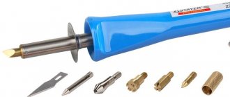
Soldering iron tips are distinguished by shape and material. The shape is simple: the most primitive and at the same time universal is the awl-shaped sting. Variations are possible in the shape of a spatula, a cone with a blunt end, with a bevel, and others. The main task when choosing a shape is to achieve the maximum area of contact with a specific type of parts to be soldered, so that the heating is powerful and at the same time short-lived.
Copper soldering iron tips
In terms of material, almost all tips are copper, but they come with or without coating. Copper tips are coated with chromium and nickel to increase heat resistance and eliminate oxidation of the copper surface. Coated tips are very durable, but are slightly less wet with solder and require careful handling. To clean them, brass shavings and viscose sponges are used.
Nickel plated tips
Uncoated tips can rightfully be classified as consumables for soldering. During operation, such a tip periodically becomes covered with a layer of oxides and the solder stops sticking to it. The working edge needs to be re-cleaned and tinned, so with intensive use the tip wears off quite quickly. To slow down the burning of the tip, it is recommended to first forge it and then sharpen it to give the desired shape.
What and how to tin/solder?
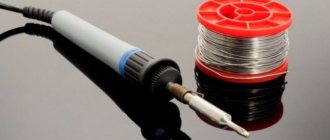
For the following operations you will need a special electric heating tool: a soldering iron, a futor or a soldering torch. Soldering at home most often involves an electric soldering iron with a tinned copper tip. Its device is shown in pos. 1 pic. “For complete happiness,” an amateur solderer needs 16-20 W rod soldering irons for microcircuits and printed circuit boards, pos. 2a, 40-50 W (item 2b), for electrical wires and mounted mounting of radio electronics components, and 80-150 W (item 2c), for assembling small metal structures by soldering.
Design and types of electric soldering irons with tinned copper tip
If you are not going to work with microchips (phones, tablets, computers) and soldering steel with a thickness of more than 0.5-0.6 mm, you can get by with a set of soldering irons of 25 W (pos. 3a) and 60-65 W, pos. 3 b. Suddenly there will be a need to solder metal profiles with a wall thickness of up to 3-4 mm and/or a thick steel sheet, you will need a radiator “axe” soldering iron for 300-400 W, pos. 4.
The tips of low-power soldering irons (items 2a, 2b, 3a, 3b) are not initially forged and therefore oxidize (burn) quite quickly. To increase their durability, and at the same time to mold them in the desired way, the rod removed from the soldering iron is forged with a mechanic’s hammer on the anvil of a table vice. There is no need to “sharpen” it with a file after this, and it is not necessary, so as not to erase the outer compacted layer of copper. After forging, the tip is immediately coated with activated flux.
Compressors are a reliable and, most importantly, economical solution to the problem- Operating principle and design of vortex blowers
ISO 27001 certificate in St. Petersburg in 1 day
Now you will need hard rosin and soft, fairly refractory solder (see below): POS-10, POS-30 or POS-40. The soldering iron rod is inserted into place, fixed if there is a locking screw, and the soldering iron is connected to the network. As the flux boils away during heating, the tip is immersed in rosin so that it does not become exposed. When the rosin around the tip begins to bubble, rub it with a stick of solder until an even, dense layer is obtained over the entire surface of the tip. Filamentous solder on a coil is not very good in this case; it is for soldering small parts.
While we were preparing the soldering iron, the flux on the soldering surfaces did its job: under its layer they are clean, you can tin. The critical point here is the thickness of the parts:
- Less than 1/8 of the diameter of the soldering iron rod - will heat through to the melting temperature of the solder in less than 7 seconds. The flux will not have time to boil away.
- More than 1/6 of the same value - it will warm up in more than 10 s, the flux will boil away, the parts will become exposed and oxidize.
- 1/8-1/6 of the diameter of the rod - it is necessary, most often based on your own experience, to tin with low-melting solder under a high-boiling flux. Or use a more powerful soldering iron.
In the first case, a drop of solder is taken onto the tip, transferred to the soldered surface, and if:
- The wire is thin - easily, without pressure, move along the bare end with a tip from one side and then from the opposite side until the solder spreads. The wire is held with the tip down. A drop of excess solder that has flowed down there is removed with a soldering iron.
- The wire is thick - the tip is moved in a spiral back and forth.
- A flat thin long part - solder is applied to the end and the tip is moved along. When the untinned edges of the part appear behind the tip, apply more flux to the untinned area, take another drop of solder and continue tinning.
- The long, wider part is the same as in the previous one. case, but the sting is led like a snake.
- Wide part - the sting is moved in a spiral from the center to the edges.
To tinning thick parts, use filament solder with flux, the so-called. harpius: this is a thin flexible tube of solder foil, in the lumen of which there is powdered rosin. Tinning begins from the edge of long or from the middle of wide parts. The end of the harpius is applied to the place where tinning begins, and heated with a soldering iron until it melts. The sting movements are the same as before. cases. Solder is fed under the tip as it is consumed. Apply it to the sting - it will stick to it until a large drop forms, which flows where it is not needed.
Temperature conditions and materials
The classification of soldering processes is based on the methods of operation, the conditions under which the connections are made, and the types of consumables. The concepts and types of soldering are described in detail by GOST 17325.
Soldering is called high-temperature or hard soldering if the solder is heated to a temperature of 450 ℃ or higher. Otherwise, you have to deal with the low-temperature type (soft).
For the low-temperature type, low-melting solders are used. These include alloys of tin and lead, bismuth, gallium, and indium. Refractory solders include copper-silver and copper-zinc solders.
Due to the need for new materials and environmental safety requirements, soldering technologies are constantly changing. Lead solders are being used less and less, smoke eliminators are being installed, and laser and ultrasonic equipment are being developed.
The introduction of robotic systems, which can significantly speed up work, plays a significant role in the development of soldering.
Features of soldering wires
In the preliminary connection of soldered parts, the most problems arise with the wires: to do this, you have to touch them with your hands, which causes the metal surface to become dirty, and the wire solders have to withstand mechanical loads more often than other soldered joints.
Twists of wires
Before soldering the wires, they must be twisted correctly. The main types of wire twists for soldering are shown in Fig. Each of them has its own purpose:
- Bandage twists are used to connect rigid (thick single-core) current-carrying wires, i.e. through which electrical power is transmitted. Especially – external wires. The band connection ensures sufficient electrical contact even if the oxidized junction is not soldered or overheated.
- Grooved twists are made on wires in low-melting insulation (plain PVC, polyethylene), when complete spreading of the solder with minimal heating is required. Grooved twists are heated only along the groove.
- Simple twists can be used to connect both single-core and multi-core wires that have just been stripped of insulation (shiny).
- Simple sequential twisting, so-called. straight British, or simply British, is applicable for connecting current-carrying wires of flexible cables with a cross-section of up to 1.4 square meters. mm, not subject to regular heavy mechanical loads, e.g. electrical extension cords or temporary sheds.
Electrical wires that experience regular and/or constant mechanical stress must be multi-core. They are twisted as shown in the figure below: the ends are marked, the “brooms” are pushed into each other and twisted in the British way. Soldered with high-strength low-melting solder, e.g. POSK-50 (see below) with activated flux that does not require removal of residues, also see below.
Parallel (dead-end) twists of wires with a cross-section of over 0.7 square meters. mm, it is advisable to solder by immersion in molten solder, see below. Otherwise, you will have to heat it either for a long time, or with a too powerful soldering iron, which will cause the insulation to creep and the flux to boil away prematurely.
Note: single-core tinned wires – leads of radio electronics parts – can be soldered end-to-end or with a crochet hook, see fig. on right.
What is soldered, but not soldered
Flexible coaxial cables and cables for computer networks such as twisted pair (“vitukha”) are not intended for connection by soldering. An experienced cable technician who has a complete understanding of the electrodynamics of signal transmission lines can, in exceptional cases, make a coupling on them. But when performed by an amateur, even if he is otherwise a qualified electronics engineer and installer, the throughput and noise immunity of the line will fall below the permissible level, up to complete loss.
How to clean and preserve the sting
The soldering iron tip is cleaned of solder residues by rubbing it against a soft porous or fibrous pad. Foam rubber is most often used, but this is not the best option: it burns and sticks to the sting. The best material for cleaning it is natural felt or basalt cardboard. But even better is 2-step cleaning, first with a sponge-tangle made of metal tape, and then with felt. After cleaning, turn off the soldering iron, insert an even hotter tip into the solid rosin and wait until it stops bubbling. Then the tip is removed and held with the end down so that the excess rosin drains off. Once it has cooled completely, the soldering iron can be stored.
GOST 17325-79. Soldering and tinning: basic terms and definitions
This interstate standard establishes clear terms and definitions that should be used in technical documentation. It covers all areas of the technologies considered: from general concepts to connection defects.
The alphabetical index of terms has been translated into English and German.
The standard has valid status.
Tinning is a process considered to be a precursor to soldering. After processing, a thin layer of tin forms on the surface.
Solders and fluxes
Now it’s time to accurately select the working solder and flux for it, because... soldering, unlike half-solder, must not only adhere tightly to the base metal, but also be strong itself. A summary of information about solders and fluxes of widespread use from the old reference book is given in Fig. In relation to the present time, there is not much left to add to it.
Characteristics of solders and fluxes for wide application
Solders
Solders from POS-90 to Avia-2 are soft for low-temperature soldering. Only electrical contact is guaranteed. POS-30 and POS-40 solder copper, brass, bronze with inactive fluxes, and the same with steel, and steel with steel with active ones. POSSr-15 can be soldered galvanized sheets with inactive fluxes; other solders corrode the zinc to steel and the soldering soon falls off.
34A, MF-1 and PSR-25 hard solders, for high-temperature soldering. Solder 34A can be used to solder aluminum in a flame (see below, about soldering aluminum) with special fluxes, see ibid. MF1 solder is used to solder copper to steel with activated flux. “Low strength requirements” in this case means that the strength of the joint is closer to the strength of copper than steel. When soldered with a dry soldering iron (see below), PSR-25 is suitable for soldering jewelry, Tiffany stained glass, etc.
Fluxes
Soldering fluxes are divided into neutral (inactive, acid-free), which do not react chemically with the base metal or interact to an insignificant extent, activated, which chemically act on the base metal when heated, and active (acidic), which act on it even when cold. In regard to fluxes, our century has brought the most innovations; mostly still good, but let's start with the unpleasant ones.
First, technically pure acetone for washing rations is no longer widely available due to the fact that it is used in the underground production of drugs and itself has a narcotic effect. Substitutes for technical acetone are solvents 646 and 647.
Secondly, zinc chloride in activated flux pastes is often replaced with sodium teraborate - borax. Hydrochloric acid is a highly toxic, chemically aggressive volatile substance; Zinc chloride is also toxic, and when heated it sublimates, i.e. evaporates without melting. Borax is safe, but when heated it releases a large amount of water of crystallization, which slightly impairs the quality of soldering.
Note: Borax itself is a soldering flux for dip soldering, see below.
The good news is that there is now a wide range of fluxes on sale for all soldering occasions. For ordinary soldering work, you will need (see figure) inexpensive SCF (alcohol rosin, former CE, second in the list of acid-free fluxes in Table I.10 in the figure above) and soldering (etched) acid, this is the first acid flux on the list. SKF is suitable for soldering copper and its alloys, and soldering acid is suitable for steel.
SKF rations must be washed: rosin contains succinic acid, which destroys the metal with prolonged contact. In addition, accidentally spilled SCF instantly spreads over a large area and turns into an extremely sticky muck that takes a very long time to dry, the stains from which cannot be removed from clothes, furniture, or the floor and walls. In general, SKF is a good flux for soldering, but not for slow-witted people.
A complete substitute for SCF, but not so nasty if handled carelessly, is TAGS flux. Steel parts are more massive than is permissible for soldering with soldering acid, and more durable, they are soldered with F38 flux. The universal flux can be used to solder almost any metal in any combination, incl. aluminum, but the strength of the joint with it is not standardized. We'll come back to soldering aluminum later.
Note: radio amateurs, keep in mind that there are now fluxes on sale for soldering enameled wires without stripping!
Reaction-flux
The reactive flux type of soldering is based on a chemical reaction in which solder is formed from flux when combined with metal. This is clearly visible when aluminum parts are connected to each other.
To join them, a flux based on zinc chloride is used. When heated, zinc begins to interact with aluminum, turning into metal solder.
It fills the entire gap space, making the soldering area a strong connection. In this case, it is very important to accurately observe the proportions of the applied flux. There must be a lot of it so that pure zinc in the required quantity can be released from the flux powder.
Sometimes with this type of soldering it is necessary to add zinc solder in small quantities as an addition to the main process. This is usually done if two pieces are overlapped.
Other types of soldering
Those who like to tinker also often solder with a dry soldering iron with a bronze tip, the so-called. soldering pencil, pos. 1 in Fig. It is good where solder spreading outside the soldering zone is unacceptable: in jewelry, stained glass, soldered objects of applied art. Sometimes surface-mounted microchips are also dry-soldered with pin spacing of 1.25 or 0.625 mm, but this is a risky business even for experienced specialists: poor thermal contact requires excessive soldering iron power and prolonged heating, and it is impossible to ensure stable heating during manual soldering. For dry soldering, use harpius from POSK-40, 45 or 50 and flux pastes that do not require removal of residues.
Other types of soldering that can be done at home
Dead-end twists of thick wires (see above) are soldered by immersion in a futorka - a bath of molten solder. Once upon a time, the futorka was heated with a blowtorch (pos. 2a), but now this is primitive savagery: an electrofutorka, or soldering bath (pos. 2) is cheaper, safer and gives better soldering quality. The twist is introduced into the futor through a layer of boiling flux, which is applied to the solder after it has melted and warmed up to operating temperature. The simplest flux in this case is rosin powder, but it soon boils away and burns even faster. It is better to flux the futor with brown, and if a soldering bath is used for galvanizing small parts, then this is the only possible option. In this case, the maximum temperature of the futor should not be lower than 500 degrees Celsius, because zinc melts at 440.
Finally, solid copper in products, e.g. pipes are soldered using high-temperature flame soldering. It always contains unburned particles that greedily absorb oxygen, so the flame has, as chemists say, restorative properties: it removes residual oxide and prevents the formation of new ones. At pos. 3 you can see how the flame of a special soldering torch literally blows out everything unnecessary from the soldering area.
Manual high-temperature flame soldering
High-temperature soldering is carried out, see Fig. on the right, evenly rubbing the soldering area with pressure with a stick of hard solder 2. The flame of the torch 3 should follow the solder so that the hot spot is not exposed to air. First, the soldering zone is heated until the colors become tarnished. You can solder something else to the surface tinned with hard solder using soft solder as usual. For more information on flame soldering, see later when it comes to pipes.
It’s funny, but in some sources the soldering torch is called a soldering station. Well, a rewrite is a rewrite, whatever you get from it. In fact, a desktop soldering station (see next figure) is equipment for fine soldering work: with microchips, etc., where overheating, spreading of solder where it is not needed, and other flaws are unacceptable. The soldering station accurately maintains the set temperature in the soldering zone, and, if the station is gas, it controls the gas supply there. In this case, the torch is included in its kit, but the soldering torch itself, the soldering station, is nothing more than a quarry - St. Basil's Cathedral.
Desktop soldering stations
Capillary
Capillary type of soldering is the most common. Many people who use it are not even aware of this name. The essence of the technology is as follows.
The solder is melted, it heats up and fills the space between the two prepared parts. Wetting the surface of parts and retaining solder occurs largely due to the capillarity effect.
The capillary type of soldering is common in everyday life and in various industries. To do this you will need a soldering iron or torch. In fact, any type of soldering can be considered to a certain extent capillary, since in each there is capillary wetting of the workpiece surfaces with liquid solder.
How to solder aluminum
Fluxes for aluminum soldering
Thanks to modern fluxes, soldering aluminum has become generally no more difficult than copper. F-61A flux is intended for low-temperature soldering, see fig. Solder – any analogue of Avia solders; There are different ones on sale. The only thing is that it is better to insert a tinned bronze rod into the soldering iron with notches on the tip approximately like a file. Under the layer of flux, it will easily scrape off the strong oxide film, which prevents aluminum from being soldered just like that.
F-34A flux is intended for high-temperature soldering of aluminum with 34A solder. However, you need to be very careful when heating the soldering zone with a flame: the melting point of aluminum itself is only 660 Celsius. Therefore, it is better to use flameless chamber soldering (furnace-heated soldering) for high-temperature aluminum soldering, but the equipment for it is expensive.
Copper plating of aluminum for soldering
There is also a “pioneer” method of soldering aluminum with preliminary copper plating. It is suitable when only electrical contact is required and mechanical stress in the soldering area is excluded, for example, if it is necessary to connect an aluminum casing to the common busbar of a printed circuit board. “In a pioneering way,” aluminum soldering is carried out on the installation shown in Fig. left. Copper sulfate powder is poured in a heap into the soldering zone. A harder toothbrush, wrapped in bare copper wire, is dipped into distilled water and the vitriol is rubbed with pressure. When a copper spot appears on the aluminum, it is tinned and soldered as usual.
Contact reaction
A type of soldering called “contact-reaction” or “reactive” means the process of fusion when two parts made of different metals come into contact.
A phase transition of the metal from solid to liquid occurs, followed by hardening and fusion. Often such a connection is made through a thin layer, which is applied to one of the workpieces by galvanic or other means.
Low-melting materials – eutectics – are used. This way you can combine silver and copper, where a copper-silver alloy will be formed between the parts. They carry out soldering of tin and bismuth, silver and beryllium, graphite and steel.
You can solder aluminum to other materials through a layer of copper or silicon. The connection is strong, soldering time takes a fraction of a second.
Fine soldering
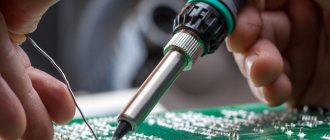
Soldering printed circuit boards has its own peculiarities. How to solder parts onto printed circuit boards, in general, see the small master class in the drawings. Tinning of wires is no longer necessary, because the terminals of the radio components and chips are already tinned.
In amateur conditions, firstly, there is little point in tinning all current-carrying paths if the device operates at frequencies up to 40-50 MHz. In industrial production, boards are tinned using low-temperature methods, for example. spraying or galvanic. Heating the tracks along their entire length with a soldering iron will worsen their adhesion to the base and increase the likelihood of delamination. After installing the component, it is better to varnish the board. This will immediately darken the copper, but this will not affect the performance of the device in any way, unless we are talking about microwaves.
Soldering radio-electronic components onto a printed circuit board
Then, look at the ugly thing on the left of the trail. rice. For such a marriage, and in the bad memory of the Soviet MEP (Ministry of Electronic Industry), installers were demoted to loaders or helpers. It’s not even a matter of appearance or excessive consumption of expensive solder, but, firstly, the fact that during the cooling of these plaques both the mounting pads and the parts overheated. And large heavy influxes of solder are rather inert weights for already weakened tracks. Radio amateurs are well aware of the effect: if you accidentally push a “cuttlefish” board onto the floor, 1-2 or more tracks peel off. Without waiting for the first re-soldering.
Incorrectly and correctly soldered circuit boards
Solder beads on printed circuit boards must be round and smooth with a height of no more than 0.7 times the diameter of the mounting pad, see on the right in Fig. The tips of the leads should protrude slightly from the beads. By the way, the board is completely homemade. There is a way at home to make a printed edit as accurate and clear as a factory one, and even display the inscriptions you want. White spots are reflections from the varnish during photography.
Swellings that are concave and especially wrinkled are also a defect. Just a concave bead means that there is not enough solder, and a wrinkled bead means that air has penetrated into the solder. If the assembled device does not work and there is a suspicion of a faulty connection, look first in these places.
ICs and chips
In essence, an integrated circuit (IC) and a chip are the same thing, but for clarity, as is generally accepted in technology, we will leave the “microchip” microcircuits in DIP packages, up to and including large ones in terms of the degree of integration, with pins separated by 2.5 mm, installed in mounting holes or soldering pins if the board is multilayer. Let the chips be ultra-large “million-dollar” ICs, mounted on the surface, with pin pitches of 1.25 mm or less, and the microchips – miniature ICs in the same cases for phones, tablets, and laptops. We do not touch processors and other “stones” with rigid multi-row pins: they are not soldered, but installed in special sockets, which are sealed into the board once when it is assembled at the enterprise.
Soldering iron grounding
Modern CMOS (CMOS) ICs are the same in sensitivity to static electricity as TTL and TTLSh, holding a potential of 150 V for 100 ms without damage. The amplitude value of the effective network voltage is 220 V - 310 V (220x1.414). Hence the conclusion: you need a low-voltage soldering iron, for a voltage of 12-42V, connected through a step-down transformer on the hardware, not through a pulse generator or capacitive ballast! Then even a direct test on the tip will not ruin expensive chips.
There are still random, and even more dangerous, surges in mains voltage: welding was turned on nearby, there was a power surge, the wiring sparked, etc. The most reliable way to protect yourself from them is not to remove “stray” potentials from the soldering iron tip, but not to let them escape from there. For this purpose, even at special enterprises of the USSR, the circuit for switching on soldering irons was used, shown in the figure:
Grounding diagram for a low-voltage electric soldering iron
The connection point C1-C2 and the transformer core are connected directly to the protective grounding loop, and the screen winding (an open turn of copper foil) and the grounding conductors of the workplaces are connected to the middle point of the secondary winding. This point is connected to the circuit with a separate wire. If the transformer has sufficient power, you can connect as many soldering irons as you like to it, without worrying about grounding each one individually. At home, points a and b are connected to a common ground terminal with separate wires.
Microcircuits, soldering
Microcircuits in DIP packages are soldered like other electronic components. Soldering iron – up to 25 W. Solder – POS-61; flux - TAGS or alcohol rosin. You need to wash off its remains with acetone or its substitutes: alcohol takes the rosin hard, and it is not possible to completely wash it off between the legs either with a brush or a rag.
As for chips, and especially microchips, soldering them manually is strongly not recommended for specialists of any level: this is a lottery with very problematic winnings and very likely losses. If it comes to such subtleties as repairing phones and tablets, you will have to fork out for a soldering station. Using it is not much more difficult than a hand soldering iron, see the video below, and the prices of quite decent soldering stations are now affordable.
Advantages and disadvantages
Before we talk about what soldering is, let's consider the main pros and cons of the technology. The advantages include:
- Ability to connect surfaces with different physical and chemical properties.
- Soldering technology is used to work in hard-to-reach places where welding is impossible.
- There are no requirements for the shape and size of products.
- It is possible to perform processing on all touching planes.
- Soldering does not create internal stress, which has a positive effect on the quality of the metal.
- The relative simplicity of the process, compared to welding, allows you to solder workpieces after obtaining basic knowledge in this area.
Experts identify three shortcomings.
- Low connection strength. This is due to the properties of the materials that are used as solder. Hence the next minus.
- Low heat resistance. You cannot work with parts whose operation is associated with elevated temperatures. For example, sealing a hole in a kettle will definitely not please you with quality and durability.
- Poor performance. For this reason, soldering is practically not used in mass production, and the work performed is associated with point impacts.
Video: microcircuit soldering lessons
Microcircuits, desoldering
“Correctly”, ICs are not desoldered for testing during repairs. They are diagnosed on site using special testers and methods, and the unusable ones are removed once and for all. But amateurs cannot always afford it, so just in case, below we provide a video about methods for desoldering ICs in DIP packages. Craftsmen also manage to desolder chips with microchips, for example, by slipping a nichrome wire under a number of pins and heating them with dry soldering irons, but this is an even less winning lottery than manual installation of large and extra-large ICs.
Video: desoldering microcircuits - 3 methods
Selective
It cannot be said that the selective type of soldering is fundamentally different from capillary soldering. Solder and heat are used in the same way. But the solder is melted only in selected places (local points) to which the elements are planned to be attached.
Selective soldering is used mainly for the manufacture of circuit boards and pin components. It is similar to the wave method used for soldering SMD chips.
Selective soldering installation is equipment belonging to the semi-automatic category. It is not cheap, but it saves consumables almost ten times compared to the wave, so it is distributed wider and wider.
How to solder pipes
Copper pipes are soldered using a high-temperature method with any hard copper solder with activated flux paste, which does not require removal of residues. Next, there are 3 options:
- In copper (brass, bronze) couplings - soldering fittings.
- With full distribution.
- With incomplete distribution and compression.
Soldering copper pipes into fittings is more reliable than others, but requires significant additional costs for couplings. The only case when it is irreplaceable is a drainage device; then a tee fitting is used. Both soldered surfaces are not tinned in advance, but are coated with flux. Then the pipe is inserted into the fitting, securely fixed and the joint is soldered. Soldering is considered complete when the solder stops going into the gap between the pipe and the coupling (0.5-1 mm is needed) and protrudes outward as a small bead. The fastener is removed no earlier than 3-5 minutes after the solder has hardened, when the joint can already be held by hand, otherwise the solder will not gain strength and the joint will eventually leak.
How pipes with full distribution are soldered is shown on the left in Fig. The “distributed” soldering holds the same pressure as the fitting one, but requires additional pressure. special tools for unrolling the socket and increased solder consumption. Fixing the soldered pipe is not necessary; it can be pushed into the socket with a twist until it jams tightly, so soldering with full distribution is often done in places that are inconvenient for installing the clamp.
Soldering copper pipes
In home wiring made from thin-walled pipes of small diameter, where the pressure is already low and its losses are insignificant, soldering with incomplete expansion of one pipe and narrowing of the other may be advisable, pos. I on the right in Fig. To prepare the pipes, a round stick made of hard wood with a conical tip of 10-12 degrees on one side and a truncated-conical hole of 15-20 degrees on the other, pos. II, is sufficient. The ends of the pipes are processed until they fit into each other without jamming for approx. by 10-12 mm. The surfaces are tinned in advance, more flux is applied to the tinned ones and they are connected until they jam. Then they heat until the solder melts and prop up the narrowed pipe until it jams. Solder consumption is minimal.
The most important condition for the reliability of such a joint is that the narrowing must be oriented along the flow of water, pos. III. Bernoulli's school law is a generalization for an ideal fluid in a wide pipe, and for a real fluid in a narrow pipe, due to its (liquid) viscosity, the maximum pressure jump shifts opposite to the current, pos. IV. A component of pressure force arises, pressing the narrowed pipe against the distributor, and the soldering turns out to be very reliable.
What else?
Oh yes, soldering iron stands. The classic one, on the left in the figure, is suitable for any rod. Where the trays for solder and rosin should be placed on it is up to you; there are no regulations. For low-power soldering irons with an apron, simplified stands-brackets in the center are suitable.
Correct and incorrect stands for soldering irons
Soldering stations are equipped mainly with spring or tubular cradle-sockets for soldering irons. In them, the entire hot part of the tool is inaccessible to touch, but it is more likely to pass the soldering iron past them, concentrating on soldering small “scattered” parts. But what you definitely shouldn’t do, and what is directly prohibited by TB, is a stand made from scrap materials, in which the soldering iron lies on the trays for consumables, on the right in Fig.
Where is it used?
Soldering technology takes an honorable second place in terms of frequency of use for joining materials . The championship belongs to welding. However, there are areas where, for certain reasons, it is impossible to use welding equipment and there is no worthy alternative to soldering. The statement is valid for the following industries:
- Production of electronic control boards. Soldering is used to attach miniature components.
- Refrigeration equipment. Copper tubes and heat exchangers are connected only by soldering. Repair of radiators for land transport and special equipment is carried out using this technology.
- Joining high-alloy alloys that are difficult to weld.
- Aviation industry. The intermediate layer of aircraft skin has a honeycomb structure. For its production, soldering is used in thermal furnaces.
The technology is used in cases where other types of connections, such as riveting, gluing or bolting, cannot be used for some reason. An important condition is the absence of requirements for high contact strength.
