Ultrasonic processing is the processing of materials (products) or substances using ultrasound (usually with a frequency of 15-50 kHz) in technological processes.
Liquid, gaseous and solid media are subjected to ultrasonic treatment to accelerate mass and heat transfer, chemical reactions, destruction, compaction and coagulation, etc. In particular, ultrasound is used to intensify the processes of dispersing reagents, separating fine sludge particles, extinguishing flotation foams, cleaning the surfaces of mineral particles, classifying technological suspensions, filtering industrial liquids and wastewater, producing aerosols, purifying gases from solid particles, drying bulk materials, increasing productivity of drilling and cutting rocks, etc.
Physical properties and features of ultrasound propagation
Ultrasonic vibrations are elastic vibrations of a material medium with a frequency exceeding the limit of audibility (15–20 kHz).
Ultrasonic vibrations can propagate in any elastic media: liquid, solid, gaseous. There are three types of ultrasonic waves - longitudinal, transverse and surface. In solids, waves of all three types can propagate; in liquid and gaseous bodies, only longitudinal waves of rarefaction and compression can propagate. Ultrasound in gases, and in particular in air, propagates with high attenuation. Liquids and solids are good conductors and exhibit much less attenuation. For example, in water the attenuation of ultrasound is 1000 times less than in air.
The short length of ultrasonic waves is the basis for considering their propagation by methods of geometric acoustics. Physically, this leads to a ray propagation pattern. This leads to such properties of ultrasound as the possibility of geometric reflection and refraction, as well as sound focusing. The next important feature of ultrasound is the ability to obtain high intensity even with relatively small vibration amplitudes. Ultrasonic waves of high intensity are accompanied by a number of effects that can only be described by the laws of nonlinear acoustics.
An important feature of ultrasound is the ability to concentrate energy at relatively small vibration amplitudes, since the energy flux density is proportional to the square of the frequency. Ultrasonic waves of high intensity are accompanied by a number of effects. Thus, the propagation of ultrasonic waves in gases and liquids is accompanied by the movement of the medium, which is called acoustic flow.
Important phenomena of acoustic flow include cavitation, which consists of the growth in an ultrasonic field of bubbles from existing submicroscopic nuclei of gas or vapor in a liquid, which begin to pulsate at the frequency of ultrasound and collapse in the positive pressure phase. When gas bubbles collapse, high pressures arise, on the order of thousands of atmospheres, and spherical shock waves are formed. Acoustic microflows arise near the pulsating bubbles. Ultrasonic phenomena in the cavitation field are used in the production of emulsions, aeration of liquids, cleaning surfaces from contamination, degreasing and etching, ultrasonic dispersion, acoustic emulsification, etc.
The main parameters of ultrasonic vibrations are: wavelength λ – the distance between two adjacent points that are in the same phase; amplitude of oscillations A – the greatest displacement of the oscillating point from the equilibrium position; oscillation frequency f – number of oscillations per unit time; oscillation period T – time of propagation of wave motion over a distance equal to the wavelength; average speed of oscillatory movements V; speed of propagation of sound waves C.
Deburring using RCD
This operation is based on increasing the cavitation and erosion activity of the acoustic field when introducing ultra-small particles from 1 micron into the abrasive flow. This size is comparable to the radius of impact of a shock sound wave, which makes it possible to destroy weak areas of burrs. The working process is organized in a special liquid medium with a glycerin mixture. A special equipment is also used as a container - a phytomixer, the glass of which contains suspended abrasives and a working part. As soon as an acoustic wave is applied to the working medium, the random movement of abrasive particles begins, which act on the surface of the workpiece. Fine grains of silicon carbide and electrocorundum in a mixture of water and glycerin provide effective removal of burrs up to 0.1 mm in size. That is, ultrasonic treatment ensures accurate and high-precision removal of microdefects that could remain even after traditional mechanical grinding. If we are talking about large burrs, then it makes sense to increase the intensity of the process by adding chemical elements like copper sulfate to the container.
Operating principle of installations for generating ultrasonic vibrations
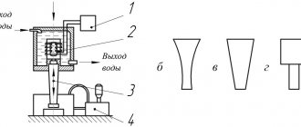
Ultrasonic installations used for dimensional processing of materials (Fig. 1) contain: an electrical vibration generator; acoustic transducer; ultrasonic oscillatory system, supply and removal system of coolant and suspension with abrasive.
Figure 1 – Installation diagram for ultrasonic dimensional processing (a) and concentrator diagrams: exponential (b), conical (c) and stepped (d) : 1 – generator; 2 – acoustic transducer; 3-ultrasonic oscillatory system; 4 – system for supplying coolant and suspension with abrasive
Ultrasonic generators are designed to convert electric current at industrial frequency (50 Hz) into high frequency current.
The acoustic transducer is designed to convert electrical high-frequency vibrations into mechanical ones. For dimensional processing purposes, magnetostrictive and piezoelectric transducers are predominantly used.
Magnetostrictive converters use the effect of longitudinal magnetostriction, which consists in changing the length of a core of ferromagnetic material placed in a magnetic field. The simplest magnetostrictive converter is a core made in the form of a rod or frame with an excitation winding. When an alternating electric current passes through the winding, an alternating magnetic field is induced in the core, and elastic deformations occur, causing longitudinal vibrations of the core.
To reduce losses due to Foucault currents, metal cores are assembled from stamped thin plates or wound from thin tape. Magnetostrictive converters are water-cooled. Their maximum electroacoustic efficiency in the frequency range 20...30 kHz is 50...70%. As the oscillation frequency increases, its value decreases.
Magnetostrictive converters are also made from ferrites. They have virtually no eddy current losses. Therefore, ferrite cores are made monolithic. To magnetize them, plates of ferrite permanent magnets are used, which are inserted or glued into the magnetic circuit of the converter. The electroacoustic efficiency of ferrite transducers reaches 80...85%. They do not require high supply voltage or forced water cooling.
Piezoelectric transducers use the piezoelectric effect, the essence of which is that in crystals with a certain type of lattices, under the influence of an electric current, internal voltages arise that are proportional to the electric field strength. As a result, the dimensions of the crystal change in accordance with the change in electric current.
All piezoelectric materials are divided into natural and artificial. Natural ones are quartz, seignette salt, tourmaline; artificial – ceramics of barium titanate TsTS-19 and lead titanate TsTS-23.
Quartz transducers are expensive and their sizes are limited. Piezoceramics are much cheaper and require lower exciting voltages.
The oscillatory system is designed to transmit vibrations occurring in the converter to the working units of the installation and, ultimately, to the surface being processed. The oscillatory system includes: a waveguide, a concentrator, and an instrument.
A waveguide is a rod or pipe of constant cross-section that connects an acoustic transducer to a concentrator.
The concentrator is designed to increase the amplitude of the mechanical vibrations of the instrument by ensuring resonance of the frequencies of the vibrator (magnetostrictive or piezoelectric) with the actuating instrument. The main forms of concentrators are presented in Figure 1 b, c, d.
Monitoring the implementation of RCD
The technological process is under the control of the operator, who monitors the parameters of the influencing vibrations. In particular, this applies to the amplitude of vibrations, the speed of sound, and the intensity of the current supply. Using this data, control of the working environment and the impact of abrasive material on the workpiece is ensured. This feature is especially important for ultrasonic processing of tools, when several operating modes of equipment can be used in one technological process. The most advanced control methods involve the participation of automatic means of changing processing parameters based on readings from sensors that record product parameters.
The physical essence of ultrasonic processing
Ultrasonic processing is based on the impact of the tool end on the tops of the largest abrasive grains. This method consists of two main processes: impact indentation of abrasive grains, causing cracks and separation of small particles of brittle material; circulation and change of abrasive in the working area. Brittle fracture of the processed materials and, at the same time, ductile fracture of the tool occur.
When the end of the tool hits the abrasive grains, the tops of the grains are pressed into the surface layers of the part and the tool (Fig. 2 a). The introduction of abrasive particles into the tool leads only to plastic deformations, and a network of stresses appears in the surface layer of the workpiece (Fig. 2 b). Under the influence of stresses created by subsequent impacts of the tool end, microcracks expand and new ones form. A zone of destruction from particle fission appears at the moment when the maximum shear stress in the indentation zone exceeds the shear resistance. Water carrying abrasive expands microcracks, facilitates the formation of chips, delivers new abrasive to the processing area, and also cools the tool and part.
Figure 2 – Schemes of cutting processes (a) and destruction (b) during ultrasonic processing: 1 – part; 2 – tool; 3 – suspension with abrasive
A quantitative assessment of the feasibility of ultrasonic processing of a material is the fragility criterion
where is εp the shear strength of materials; σp – peel resistance. The materials of the first group (Table 1.11), which have a fragility coefficient tx ≥ 2, are most effectively processed. Soft materials: copper, lead, steel, etc., with a fragility coefficient tx < 1, are not subject to ultrasonic treatment.
Table 1.11 – Areas of application of ultrasonic treatment
| Material group | Material | Fragility criterion | Type of deformation | Nature of destruction | Application area |
| I | Glass, glass-ceramic, quartz, ceramics, ferrite, germanium, agate, etc. | tx ≥ 2 | Elastic | Fragile | Manufacturing of parts from ceramics, glass, quartz, ferrites, minerals. Processing of semiconductor materials |
| II | Tungsten and its alloys, hard alloys, hardened to high hardness, case-hardened steels, titanium alloys | 1 < tx < 2 | Elastoplastic | Brittle after hardening due to microplastic deformation | Manufacturing of die dies, upsetting matrices, parts of complex shapes made of tungsten and hard alloys |
| III | Copper, lead, mild steel, etc. | tx < 1 | Plastic | practically no destruction observed | The ultrasonic method is impractical |
All technological characteristics - process productivity, surface quality, processing accuracy, tool wear - depend on many technological and acoustic parameters, physical and mechanical properties of the material being processed, abrasive grain size, kinematic diagram of the machine, tool surface area, clamping force, processing depth.
The main movement during dimensional ultrasonic machining is tool vibration. Average speed of the main movement
The feed can be longitudinal, transverse, circular. Depending on the type of feed, as well as the cross-sectional shape of the tool, it is possible to implement various kinematic schemes for ultrasonic dimensional processing (Fig. 3).
Figure 3 – Basic schemes for performing technological operations of ultrasonic and dimensional processing of workpieces : a – cutting grooves; b – cutting out discs; c – processing of workpieces with complex shaped contours; g - turning; d – flat grinding with the end of a wheel; e – internal planetary grinding; g – cutting a groove and cutting with a rotating disk tool; h – cutting with a multi-blade band tool; and – cutting with a disk emitter; j – cutting external threads with a comb; l, m – cutting internal threads; n – processing of an elliptical hole
Analysis of the circuits shows that ultrasonic vibrations (USV) are applied to the tool along the axis (Fig. 3 a, b, d, j), or to the workpiece (Fig. 3 f, g), or simultaneously to the tool and the workpiece (Fig. 3 c, d, h, n). Obviously, applying ultrasonic testing is possible using special technological equipment equipped with powerful ultrasonic (ultrasound) equipment for applying ultrasonic testing to the machine spindle, or by radically modernizing it.
In the zones of contact interaction between the forming tool and the workpiece, as a rule, there is always a coolant, the effect of ultrasonic testing on which causes cavitation. The use of cavitation coolant is possible when grinding, drilling, reaming, countersinking, as well as when processing various surfaces of workpieces by other methods using coolant.
The effect of ultrasonic ultrasound on a tool or workpiece during the cutting process can manifest itself in the following:
- periodic changes in the magnitude and direction of the actual cutting speed vector;
- periodic changes in tool angles and thickness of the cut layer;
- changing the nature of the load application - the chip formation zone and the cutting tool, instead of a static one, experience an alternating dynamic load;
- changing the formation of the surface layer of the part during the processing of the workpiece;
- improving the conditions for coolant penetration into the cutting zone;
- changing contact interactions on the working surface of cutting tools, leading to a decrease in deformations in the chip formation zone and cutting forces.
Dimensional ultrasonic processing is most widely used in the manufacture of parts made of glass, quartz, fluorite, ferrite and other metal-ceramic materials, as well as semiconductor materials (germanium, silicon) (Table 1).
Table 1 – Technological characteristics of ultrasonic processing of various materials
| Processed material | Productivity S, mm/min | Relative tool wear q, % | Roughness Ra, µm | Processing accuracy, mm |
| Glass, ceramic glass | 5-20 | 0,5-1 | 1,25-5 | 0,02-0,1 |
| Ceramics 22ХС, ЦМ332 | 2-6 | 2-10 | 0,63-2,5 | 0,05-0,1 |
| Hard alloys VK | 0,05-0,3 | 40-100 | 0,32-2,5 | 0,02-0,05 |
| Germanium, silicon, ferrite | 3-8 | 1-2 | 0,63-1,25 | 0,03-0,10 |
| Hardened steel | 0,05-0,1 | 120-200 | 0,32-2,5 | 0,03-0,10 |
| Heat-resistant alloys | 0,02-0,03 | 150-200 | 0,63-2,5 | 0,08-0,10 |
The reasons limiting the use of ultrasonic processing of parts made of brittle materials are the relatively small depth, processing area, and high tool wear.
Therefore, this method is most appropriate for making shallow holes of complex shapes. Deep holes are ultrasonic treated with a special diamond tool without coolant supply.
Process characteristics
Processing parameters that are optimal for a specific task are pre-set. Both the configuration of the mechanical action and the properties of the workpiece material are taken into account. The average characteristics of ultrasonic treatment can be presented as follows:
- The frequency range of the current generator is from 16 to 30 kHz.
- The amplitude of vibration of the punch or its working tool - the lower spectrum at the beginning of the operation is from 2 to 10 microns, and the upper level can reach 60 microns.
- The saturation of the abrasive suspension is from 20 to 100 thousand grains per 1 cm3.
- The diameter of the abrasive elements is from 50 to 200 microns.
Varying these indicators allows you to perform not only individual high-precision linear processing, but also accurately form complex grooves and cuts. In many ways, working with complex geometric shapes has become possible thanks to the perfection of the characteristics of the punches, which can influence the abrasive composition in different models with a thin superstructure.
Application of ultrasound in electric arc surfacing
In electric arc surfacing of metal surfaces, an important element of the process is droplet transfer of molten electrode metal. The efficiency of droplet transfer of electrode metal and the productivity of surfacing noticeably increase when imparting transverse oscillatory movements to the melting electrode. Transverse vibrations of the electrode contribute to changes in the shape and structure of the deposited metal layer. It is known that during electric arc surfacing, the metal of the deposited layer consists of columnar crystals - dendrites, located perpendicular to the fusion line of the base metal. In this case, the austenitic grains of the base metal along the fusion line are the basis for growing dendrites, which is why the number and size of the latter are determined by the size and quantity of these grains. Therefore, the larger the grains of the base metal in the overheated area of the heat-affected zone, the more columnar crystals will occur in the structure of the deposited layer. By reducing the length of the liquid metal layer due to transverse vibrations, it is possible to reduce the stay of the electrode in the overheating zone. This reduces the grain size of the base metal in the fusion zone, and therefore contributes to the formation of a fine-grained structure of the deposited metal. It is known that a clear orientation of dendrites contributes to increased fragility of the deposited metal, while ultrasonic vibrations contribute to the creation of a strong, disoriented structure of the deposited layer.
The diagram of the technological installation for surfacing with ultrasonic alloying metal powder additive in a protective gas environment is shown in Figure 6.
Figure 6 – Scheme of a technological installation for surfacing with ultrasound and metal powder additive : 1 – device for transmitting ultrasonic vibrations to the electrode; 2 – waveguide-hub; 3 – electrode wire; 4 – body of the surfacing head; 5 – current conductor; 6 – device for supplying a gas-powder mixture; 7 – welded surface
The installation works as follows. Device 1 transmits longitudinal ultrasonic vibrations from the generator through the waveguide-hub 2 to the current guide 5 installed in the surfacing head. In the guide tube of the current guide 5, transverse vibrations are excited, which are transmitted to the surfacing wire 3. Vibrations of the electrode wire cause the dispersion of droplets of the electrode melt into small particles, which, having received oscillatory movements, enter the weld pool and, becoming additional crystallization centers, contribute to the formation of a homogeneous structure.
A comparative analysis of the resulting structures shows that the grain size, density and quality of the layer deposited using ultrasonic vibrations is significantly greater than that of the layer deposited without ultrasound. Moreover, when surfacing with ultrasonic vibrations there is practically no interface between the layers: coating-base, which characterizes their high adhesion and a smooth gradient of properties. Ultrasonic vibrations actively promote the processes of nucleation and formation of crystals, prevent their growth and increase the homogeneity of the structure.
When an alloying powder is introduced into the melt, the particles of which, under the influence of ultrasound, are in suspension, wetted by the melt and, evenly distributed in its volume, become additional crystallization centers, and upon solidification, this metal suspension is fixed, forming a composite alloy during crystallization with various properties: antifriction, abrasive, wear-resistant, corrosion-resistant and others. This achieves an increase in the productivity of the electric arc surfacing process and an increase in the wear resistance of the deposited layer by 1.5–1.7 times.
The deposited layer is of high quality, without metallurgical defects and with higher hardness. This surfacing method makes it possible to reduce the temperature gradient across the cross-section of the deposited layer and increase the crystallization rate, which reduces residual stresses both in the deposited layer and in the adhesion zone of the coating to the base.
Disadvantages of technology
A number of disadvantages have so far hampered the widespread use of this method. They are mainly related to the technological complexity of organizing the process. In addition, ultrasonic processing of parts requires additional operations, including the delivery of abrasive material to the working area and the connection of water cooling equipment. These factors can also increase the cost of work. When servicing industrial processes, energy costs also increase. Additional resources are required not only to ensure the function of the main units, but also to operate the safety systems and current collectors that transmit electrical signals.
Ultrasonic stamping
Cold stamping with the application of ultrasound allows for all types of shaping changes: upsetting, extrusion, sheet stamping.
A comparative analysis of the change in the specific deforming force during volumetric stamping under normal conditions and with the application of ultrasound on a plastically deformed metal indicates that in the latter case the deforming force is significantly reduced.
For example, during upsetting with flow into the cavity when ultrasound is applied, the specific deformation force decreases on average by 4 times for aluminum, for copper - by 3 times, and for steel - by 2 times.
The use of ultrasound in the process of flash-free volumetric molding reduces the specific force for copper by an average of 4.5 times, and the magnitude of the absolute reduction in the specific force (Table 2) increases with increasing degree of deformation.
Table 2 – Values of specific deforming force during flashless die forging of copper
| Deformation degree, % | Specific deforming force of stamping, MPa | Absolute reduction in specific deforming force (Δp = p1 - p2), MPa | Relative reduction in specific deforming force | ||
| under normal conditions (p1) | with ultrasonic ultrasound (p2) | p1/p2 | (Δp/p1)100, % | ||
| 1 | 105 | 30 | 75 | 3,50 | 71,6 |
| 10 | 160 | 32 | 128 | 6,00 | 80,0 |
| 15 | 205 | 35 | 170 | 5,85 | 83,0 |
| 20 | 240 | 40 | 200 | 6,00 | 83,3 |
| 25 | 275 | 52 | 223 | 5,30 | 81,1 |
| 30 | 310 | 64 | 246 | 4,85 | 79,4 |
| 35 | 355 | 87 | 268 | 4,08 | 75,5 |
| 40 | 875 | 240 | 635 | 3,64 | 72,5 |
The main reasons for reducing the specific friction force during stamping with the application of ultrasound are the reduction of contact friction forces and especially the yield stresses of the deformed metal.
The use of ultrasound in deep drawing of cups with a diameter of 6.4 mm provides a significant (2–3 times) reduction in the deforming force, while the height of the cup doubles.
When drawing cylindrical cups with a diameter of 14 mm from steel and copper, when ultrasonic vibrations were applied to the matrix, the reduction in the deforming force of drawing was 15-20% for steel, and 40% for copper. When ultrasound was applied to the punch, the reduction in the deforming force required to draw a cup from steel was 12-14%.
Thus, depending on the method of applying ultrasound to the source of deformation, ultrasonic vibrations can, to a greater or lesser extent, intensify the process of plastic flow of the metal.
How to process an ultrasound sensor?
- Before processing the ultrasound probe, it is necessary to disconnect it from the ultrasound scanner.
- Gently remove the gel from the sensor using a soft cloth dampened with running water
- Next, you need to wash the sensor with soapy water and a soft sponge.
We advise you not to rub the lens of the ultrasound sensor too much, as this can damage the lens and it will be erased in the shortest possible time.
- Then remove the remaining soapy substance and dry the ultrasound sensor in the open air and wipe with a soft cloth.
Tips for use
- Ultrasound sensors are very fragile equipment that needs to be handled with care. It is necessary to carefully ensure that the sensor is firmly held on the ultrasound scanner and that the wires do not dangle on the floor
- If the sensor is not in use, it must be placed in a case.
- Before each use of the ultrasound sensor, it is recommended to inspect for defects (chips, cracks on the body, bubbles or abrasion of the acoustic lens, creases, cable cuts)
- Do not press too hard on the ultrasound sensor if the image is not of very high quality - this does not help much. In this case, it is necessary to configure the ultrasound machine
- It is prohibited to use a damaged ultrasound probe - this can lead to disastrous consequences for both the patient and the ultrasound machine.
- During intracavitary examinations, according to SanPiN 2.1.3.2630-10, it is necessary to use special condoms for sensors. If this is not possible, then it is possible to use conventional ones without any lubricants.
Contact us: we will answer any questions about disinfecting sensors. We will help you check the current condition of the lens and crystals. We will conduct joint remote diagnostics. Or we’ll come for a full on-site inspection.
Bibliography
- Muradali D, Gold WL, Phillips A, Wilson S. Can ultrasound probes and coupling gel be a source of nosocomial infection in patients undergoing sonography? An in vivo and in vitro study. AJR Am J Roentgenol 1995; 164:1521–1524.
- Hignett M, Claman P.; High rates of perforation are found in endovaginal ultrasound probe covers before and after oocyte retrieval for in vitro fertilization-embryo transfer. J Assist Reprod Genet 1995; 12:606–609.
- Leroy S.J. “Infectious risk of endovaginal and transrectal ultrasonography: Systematic review and meta-analysis.” Hosp Infect 2013 83(2):99-106
- https://www.usclub.ru/news/item/gigienicheskie-trebovaniya-k-usloviyam-truda-medicinskih-rabotnikov%2C-vipolnyayushih-ultrazvukovie-issledovaniya.
- https://www.aium.org/officialStatements/57
- Bello TO, Taiwo SS, Oparinde DP, Hassan WO, Amure JO. Risk of nosocomial bacteria transmission: evaluation of cleaning methods of probes used for routine ultrasonography. West African J Med. 2005;24(2):167–170
- Mullaney PJ, Munthali P, Vlachou P, Jenkins D, Rathod A, Entwisle J. How clean is your probe? Microbiological assessment of ultrasound transducers in routine clinical use, and cost-effective ways to reduce contamination. Clin Radiol.2007;62(7):694–698
- Views: 38273
- Comments:
Did you like the post? Do you find it useful or interesting? Support the author!
