Operating modes
The characteristics of transformers are determined by operating conditions, where the load resistance plays a key role. The following modes are used as a basis:
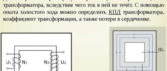
- Idle move. The outputs of the secondary circuit are in an open state, the load resistance is equal to infinity. Measuring the magnetizing current flowing in the primary winding makes it possible to calculate the efficiency of the transformer. Using this mode, the transformation ratio is calculated, as well as losses in the core;
- Under load (working). The secondary circuit is loaded with a certain resistance. The parameters of the current flowing through it are directly related to the ratio of the turns of the coils.
- Short circuit. The ends of the secondary winding are short-circuited, the load resistance is zero. The mode informs about losses that are caused by heating of the windings, which in professional language is referred to as “copper losses”.
Short circuit mode
Information about the behavior of the transformer in various modes is obtained experimentally using equivalent circuits.
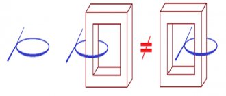
What is the core used for?
Core
serves for transformation, that is, transfer of the magnetic field from the primary winding to the secondary.
Interesting materials:
How long does the Prius battery last? How long will 1 GB of mobile Internet last? How long will 5 GB of traffic last? How long will 5GB of internet last? For how many years is a medical certificate valid for drivers? For how many years is a technical inspection valid? How many years is a driver's medical certificate valid for? For how many years do drivers get a medical certificate? How many years do you have a license in Russia? How long does a driver's license last?
How to reduce losses
The magnitude of magnetization reversal losses depends on several factors:
- properties of the substance from which the core is made. Materials that are difficult to magnetize are also difficult to remagnetize. And the more energy is consumed, which is expressed in heating;
- magnetization reversal frequencies;
- the highest value of magnetic induction.
Losses are reduced through the use of special transformer steel. It requires less energy for magnetization reversal compared to other substances.
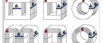
Main types of cores
Transformers have different areas of application, technical characteristics, and dimensions. They also differ in the type of magnetic circuits. Structurally, the cores are divided into three main types: The rod core is designed in the shape of the letter P and consists of two rods connected by a yoke. If necessary, protect the windings from external influences using armored magnetic cores. The yoke is located on the outer part and completely covers the rod with the winding located inside.
Cores are also classified according to the method of assembling the plates:
- set of stamped plates. The advantages of magnetic cores made from sheets include the possibility of their manufacture from not very durable materials;
- wound metal tapes. Such cores utilize magnetic energy more fully, but at the same time have an increased level of losses. Toroidal winding of tapes is the most complex, but energetically the most favorable.
There are differences in the connection of the rods to the yoke. They are collected in two ways:
Read also: Semi-automatic welding machine. How to choose
- end-to-end, when all elements are assembled from plates separately. They are connected into a single core at the last stage of transformer assembly: after the windings are laid;
- intertwined. Such magnetic cores are called laminated. They have almost no losses at the connection points.
Decoding the main parameters
The diversity in design and wide range of parameters of transformers have led to the need for their marking according to a special standard. Without having a technical description at hand, the characteristics of the device can be determined by the information printed on its surface, expressed in an alphanumeric code.
The marking of power transformers contains 4 blocks.
You can download and view GOST 15150 here (will open in a new contribution in PDF format): View file
Let's decipher the first three blocks:
Decoding of markings: 1,2,3 blocks
- The first letter "A" is attached behind the autotransformers. In its absence, the letters “T” and “O” correspond to three-phase and single-phase transformers.
- The further presence of the letter “P” informs about devices with split winding.
- The third letter means cooling; the oil natural cooling system is assigned the letter “M”. Natural air cooling is marked with the letter “C”, oil cooling with forced airflow is designated “D”, with forced oil circulation – “C”. The combination “DC” indicates the presence of forced oil circulation with simultaneous air blowing.
- The letter “T” marks three-winding converters.
- The last sign characterizes the features of the transformer:
- “N” – on-load tap-changer (voltage regulation under load);
- space – switching without excitation;
- “G” – lightning protected.
What is a transformer core: structure and types of magnetic circuits
A transformer is installed in electrical networks to convert alternating current voltage. The main parts of the device are the core and windings. Windings are coils that are wound of conductive metal around a core. For these purposes, copper or aluminum is most often used. Under load, voltage is applied to the primary winding. The current passes through the winding and causes a magnetic flux to appear in the core. As a result, voltage also arises in the second winding. And its value depends on the number of turns of wire on the primary and secondary windings.
Classification by type
An AC power transformer is a device used to transform electricity in supply networks and electrical installations of significant power.
The need for power plants is explained by the serious difference in operating voltages of main power lines and city networks coming to end consumers required for the operation of electrically powered machines and mechanisms.
and secondary windings, thanks to this their electromagnetic and electrical contact is simultaneously ensured. The windings of the devices have at least three terminals, differing in their voltage.
The main advantage of these devices should be called good efficiency, because not all the power is converted - this is significant for small differences in input and output voltages. The downside is that the transformer circuits are not isolated (lack of separation) from each other.
Autotransformers.
This term usually denotes a device powered directly from the electricity supplier, used to reduce the primary electric current to suitable values for those used in measuring and protective circuits, alarms, and communications.
Current transformers.
The primary winding of electric current transformers, the design of which provides for the absence of galvanic connections, is connected to a circuit with an alternating electric current to be determined, and electrical measuring instruments are connected to the secondary winding. The electric current flowing through it approximately corresponds to the current of the primary winding divided by the transformation ratio.
Voltage transformers.
The purpose of these devices is to reduce voltage in measuring circuits, automation and relay protection. Such protective and electrical measuring circuits in devices for various purposes are separated from high voltage circuits.
Pulse.
These types of transformers are necessary for changing short-term video pulses, which, as a rule, are repeated in a certain period with a significant duty cycle, with a minimum change in their shape. The purpose of use is the transfer of an orthogonal electrical pulse with the steepest cut and front, a constant amplitude indicator.
The main requirement for devices of this type is the absence of distortion when transferring the shape of the converted voltage pulses. The action of a voltage of any shape on the input causes the output of a voltage pulse of an identical shape, but probably with a different range or changed polarity.
Separators.
What an isolation transformer is becomes clear based on the definition itself - it is a device with a primary winding that is not electrically connected (i.e., separated) from the secondary windings.
There are two types of such devices:
- power;
- signal.
Power ones are used to improve the reliability of electrical networks in the event of an unexpected synchronous connection with the ground and live parts, or non-current carrying elements that are energized due to an insulation failure.
Signal signals are used to ensure galvanic isolation of electrical circuits
Coordinators.
How this type of transformer works is also clear from its name. Matching devices are devices that are used to match the resistance of individual elements of electrical circuits with each other with a minimum change in the signal shape. Also, devices of this type are used to eliminate galvanic interactions between individual parts of circuits.
Peak transformers.
The principle of operation of peak transformers is based on transforming the nature of the voltage, from input sinusoidal to pulsed. The polarity after the transition changes after half the period.
Twin throttle.
Its purpose, structure and principle of operation as a transformer are absolutely identical to devices with a pair of similar windings, which, in this case, are absolutely identical, wound counter-winding or coordinated.
You can also often find this device called a counter inductive filter. This indicates the scope of application of the device - input voltage filtering in power supplies, audio equipment, and digital devices.
Design features
Magnetic cores are manufactured in butt and laminated versions. The designs differ in the way the cores are connected to the yokes (the part of the cores without windings).
Butt design
The MP parts are assembled separately. Windings are installed on vertical cores. Then they are fastened with a horizontal upper yoke using pins. After this, the lower yoke is mounted. This design is convenient in that by removing the studs and removing the horizontal section, you can always change the windings. The butt design is used in shunt current-limiting devices of reactors.
Laminated structures
The rods and yokes are made in the form of layered slabs. Each package consists of two or three layers of steel plates. Connections of parts are made by inserting elements into the gaps between the layers of the magnetic circuit. This method of installing MP parts is called laching. The complexity of forming the entire structure of the transformer causes the risk of poor-quality assembly of the device.
Stages of production of lamellar magnetic cores, features of assembly of lamellar magnetic cores
In their design and properties, lamellar (laminated) magnetic cores differ significantly from twisted tape and ring (toroidal) magnetic cores. The production of cores of this type is regulated by GOST 20249-80 and is carried out according to the following scheme:
- Cutting materials. Produced on slitting units equipped with circular knives. The material is cut into strips of the required sizes.
- Cutting plates. Parts are cut using guillotines and cross-cutting units (including punching holes in the plates).
- Assembly of magnetic circuits. It is produced using the technology of assembling butt or laminated magnetic cores.
- Quality control. Measuring the main characteristics of the resulting products and their compliance with the technical specifications
The procedure consists of a set of plates in a package and their fastening (pulling) together. The parts are connected in several ways:
- studs and bolts;
- crimping staples;
- metal holder.
An important assembly condition is the isolation of fasteners from the magnetic circuit. In some cases, the package is compressed. In this case, a change in magnetic permeability and electrical resistance occurs. The procedure is performed at a pressure of 2-5 MPa, the compression force is selected depending on the materials and design of the plates.
After compression, quality control must be carried out. With its help, it is possible to find out the resulting magnetic induction and permeability, as well as the no-load current of the plate magnetic circuit.
Compliance with a precise technological process allows us to obtain reliable and durable structures that can withstand heavy loads and are ready for use in almost any conditions.
It will be interesting➡ The best radios of 2022: selection criteria and rating
How to choose the type of transformer?
The type of transformer is determined by the design of the core used in it. Currently, a wide variety of cores, especially ferrite ones, are produced. But among them three main types can be distinguished: rod (ST), armored (BT) and toroidal (TT). The rest are, in fact, their modifications with various design features.
It is impossible to make a clear choice in favor of one type or another, since each has its own advantages and disadvantages and must be used depending on the purpose and the requirements placed on it. The following requirements and their combination may be imposed on transformers: weight and size, cost, influence of internal and external magnetic fields, design factors and manufacturability.
The main types of transformer core designs: rod CT, armored BT and toroidal TT transformers (from left to right).
Under the condition of a minimum voltage drop (∆U) at industrial frequency (50 Hz), the BT has the smallest volume, and the CT has the smallest weight. Rod transformers are somewhat inferior to armored ones (up to 10%). With an increase in frequency, in terms of weight, CT improves its parameters compared to BT, and in terms of volume, it deteriorates. With increasing frequency, CTs significantly improve their weight and size indicators. Thus, provided that the voltage drop is minimal at a frequency of 50 Hz, the use of armored cores (AC) is recommended, and at higher frequencies, toroidal cores (CT) should be used if weight and volume play a decisive role.
If the key requirement for a transformer is constant operating temperature (∆T), then the recommendations are different. At low power, BT have an advantage, but in other cases, ST should be used even at higher frequencies. The use of CTs makes sense only at low powers, especially at higher frequencies, since with increasing power the advantages in mass and weight are smoothed out, and at high powers (over hundreds of watts) CTs begin to be inferior to both ST and BT.
As a result, we can say that for low-power transformers (up to 50 W) it is recommended to use BT and TT, and at high frequencies - TT. At powers of more than 50 W, the performance of CT becomes better than that of BT, and at powers of more than 250 W, it is better than that of TT.
If the condition for designing a transformer is the highest efficiency value, then at industrial frequency (50 Hz) the best performance is for BT and ST in descending order, and at higher and higher frequencies – TT and BT, also in descending order. It is also worth noting that the CT has the lowest magnetizing current, all other things being equal.
At high frequencies, leakage magnetic fields and susceptibility to external magnetic fields often play an important role. In this regard, the best performance is achieved by toroidal transformers (with the winding evenly distributed over the core), as well as rod transformers (with the winding equally distributed between the rods). The CT's own capacity is quite high compared to BT and ST.
From the point of view of manufacturability, BT and ST have the best performance. Among the disadvantages of CTs, the following can be highlighted: the need for sequential manufacturing of the core and coil, as well as the low productivity of winding the coil.
Recommended applications for various types of transformers.
| Transformer type | On stamped cores | On strip cores | ||
| Low voltage | Low power (up to 50 W) | BT | BT, ST | |
| Medium and high power (more than 50 W) | 50 Hz | BT | ST | |
| < 10 kHz | BT | ST, TT | ||
| > 10 kHz | BT, TT | TT, ST | ||
| High voltage (thousands of volts) | < 10 kHz | BT | ST, TT | |
| > 10 kHz | BT, TT | ST, TT | ||
| With high potential | < 10 kHz | BT, TT | ST, TT | |
| > 10 kHz | TT, BT | TT, ST | ||
| If reliable shielding is required | TT, ST | TT, ST | ||
| Note. The first to indicate the type of transformer, the use of which is preferable. | ||||
Features of impulse loads
For devices carrying pulsed loads, special transformers are used. They are capable of converting voltage and current under pulsed loads and withstanding their destructive effects. The types of cores of pulse transformers do not differ in shape from other types of devices.
Most often, the magnetic core is made in the form of a ferrite torus. The windings are wound on it in a special way: in the primary coil they are laid counterclockwise, and in the secondary coil they are laid clockwise.
Such a transformer can be made independently; you just need to take into account the requirements for conservation of momentum.
Main brands
There are two main brands.
Sulphurous
Brand 2212. For industrial production, thin sheets subject to cold rolling are used.
Unalloyed
It differs from carbon steel in that it contains less than 5% alloying elements.
Both types are used in the production of transformer steel.
Technical specifications
- Rated current – allowing the device to function for a long time without overheating;
- Rated voltage – the value should ensure normal operation of the transformer. It is this indicator that affects the quality of insulation between the windings, one of which is at high voltage and the other is grounded.
- Transformation coefficient; Formula for calculating the transformation ratio
Where:- U1 and U2 – voltage in the primary and secondary windings,
N1 and N2 – number of turns in the primary and secondary windings,
- I1 and I2 – current in the primary and secondary windings (usually the current in the secondary winding is 1A or 5A).
- The error in the value of the electric current is caused by magnetization;
- Rated load, which determines the normal operation of the device;
- Nominal limit factor - the maximum permissible value of the ratio of the primary value of the electric current to the nominal value;
- The maximum multiple of the secondary current is the ratio of the highest current of the secondary winding to its nominal value.
Values that CTs may have
When choosing a device, it is necessary to take into account the value of these and other characteristics.
Design and operating principle
Mandatory elements of almost any voltage conversion device are insulated windings formed from wire or tape. They are located on a magnetic circuit represented by a core made of ferromagnetic material. Communication between the coils is carried out using magnetic flux. When working with high-frequency currents (100 kHz or more), there is no core.
Transformer operating principle
The operating principle of a transformer combines the basic postulates of electromagnetism and electromagnetic induction. It can be considered using the example of a simple device with two coils and a steel core. The supply of alternating voltage to the primary winding leads to the appearance of a magnetic flux in the magnetic circuit, after which an induced emf appears in the secondary and primary windings; if you connect a load to the secondary winding, current will flow. The frequency of the output voltage remains unchanged, and its value depends on the ratio of the turns of the coils.
Transformers can be step-up and step-down, to determine this you need to find out the transformation ratio , with its help you can find out which transformer. If the coefficient is less than 1, then the transformer is step-up (this can also be determined by the values; if there is more in the secondary winding than in the primary, then it is step-up), and vice versa, if K>1, then it is step-down (if there are fewer turns in the primary winding than in the secondary).
- U1 and U2 – voltage in the primary and secondary windings,
- N1 and N2 – number of turns in the primary and secondary windings,
- I1 and I2 – current in the primary and secondary windings.
Ferrite grades
Ferrites according to their composition are divided into two groups: manganese-zinc and nickel-zinc. Manganese-zinc ferrites are designated by the letters NM, respectively, nickel-zinc substances are marked by the letters - NN. The number before the letter designation of ferrite means the value of the initial magnetic permeability in units of µinit. This indicator is given with an adjustment to the nominal value. For example, ferrite grade 4000NM has a magnetic permeability with a deviation ranging from – 800 to + 500 µinit.
Magnetic cores are of exceptional importance in the formation of devices such as transformers and other electrical devices. The initial technical characteristics of the devices largely depend on their qualitative composition.
Transformer production technology and equipment - Active steel of magnetic cores
Page 7 of 92
CHAPTER FIVE APPLICATION OF ELECTRICAL STEEL IN THE PRODUCTION OF TRANSFORMERS
1. ACTIVE STEEL MAGNETIC CORE
The magnetic system (magnetic core) has a magnetic resistance that depends on the length of the circuit, its cross-section and the properties of the material from which it is assembled—its magnetic permeability. In order to reduce the magnetizing current for a given magnetic flux, and therefore a given flux density per unit cross-section (magnetic induction), it is necessary to make the magnetic resistance of the active part of the magnetic circuit as small as possible, therefore, it is necessary to make it from a material with high permeability. Such a material is electrical steel, which has a magnetic permeability several orders of magnitude greater than air.
More than 60 years ago, electrical steel sheets alloyed with 1 - 4% silicon were produced. Currently, high-alloy hot-rolled electrical steels have a silicon content of 3.8–4.8%. In 1935, the so-called cold-rolled electrical steel was produced by cold rolling of silicon steel [L. 8]. The advantages of cold-rolled steel over hot-rolled steel are so significant that at present almost only cold-rolled steel is used in transformer construction. The best samples of this steel have specific losses p10/50 for sheets 0.35 mm thick and less than 0.5 W/kg. Reducing specific losses made it possible to increase the induction in the magnetic circuit to 1.6-1.7 T versus 1.4-1.5 T for hot-rolled steel. This made it possible to significantly reduce the size of the magnetic cores. In the transformer industry, the following grades of electrical steel were used according to GOST 802-58: a) hot-rolled electrical steel grades E22, E41, E42, E43, E43A; b) cold-rolled textured electrical steel grades E310, E320, E330 and E33O-A, E33O-AP. The best grades of cold-rolled steel - E33O, E33O-A and E33O-AP - were predominantly used. The alphabetic and numerical designations of the steel grade conventionally indicate: E - electrical steel; the first digit is the degree of alloying of steel with silicon in percentage: 1 - lightly alloyed (0.8-1.8% silicon); 2 - medium doped (1.8-2.8% silicon); 3 - highly doped (2.8-3.8% silicon); 4 - highly alloyed (3.8-4.8% silicon); the second digit is the level of specific losses: 1 - normal specific losses; 2 - reduced specific losses; 3 – low specific losses; the third digit (0) indicates that the steel is cold-rolled, textured; the letter A indicates particularly low losses of electrical steel, the letter P indicates increased precision in rolling and finishing. Electrical steel is produced both in sheets and in rolls. Sheet sizes: 150X1500, 1000X2000, 600x1500 and 860X1720 mm. Roll dimensions: width 800 and 950 mm, diameter 500 mm. The thickness of the produced electrical steel is 0.5 and 0.35 mm. Tolerances on the thickness of sheets of normal rolling accuracy are 0.5 ± 0.05 and 0.35 ± 0.04 mm for hot-rolled steel; for cold rolled steel 0.5±0.04 and 0.35±0.03 mm. Tolerances on the thickness of coiled steel are ±0.03 mm. On the surface of electrical steel, significant pockmarking, defects in edges and corners, warping1 with a box height of more than 2-4 mm per 1 m and waviness *, ** with a wave height of more than 4-6 mm per 1 m are not allowed; the wavelength or box must be less than 25 times its height.
* Cupping is a deformation of the sheet in the form of a box with bent ends of the sheet.
**Waviness is the deformation of the steel strip over its entire width and with a uniform wave pitch. The wave is visible from the end (thickness) of the steel strip.
In table Table 5-1 shows the electromagnetic characteristics of various steel grades in accordance with GOST 802-58: values of magnetic induction, specific losses at a frequency of 50 Hz and specific electrical resistance. In connection with the widespread use of cold-rolled textured steel in transformer manufacturing, we will consider some of its characteristics [L. 8]. Cold-rolled steel has special magnetic properties when, as a result of rolling and heat treatment, individual crystals are oriented, forming axes of predominant magnetization in the direction of sheet rolling and, conversely, difficult magnetization in the transverse direction. Thus, steel, which, according to the structure of the crystallographic lattice, has crystals oriented in a certain direction, is called textured. A distinction is made between steel with an edge texture, when the crystals are oriented along the rolled edge of the cube, and steel with a cubic texture, when the crystals are oriented along the side of the cube. Electrical steel with a ribbed texture has pronounced anisotropy, i.e., the dissimilarity of all or some physical properties in different directions. Such a structure provides the least resistance to magnetic flux only along the rolling direction and increased resistance to magnetic flux across or at some other angle to the rolling direction. Steel with a cubic texture has equally high magnetic properties both along and across the rolling, but this steel is not yet produced on an industrial scale.
Table 5-1
| steel grade | Sheet thickness, mm | Magnetic induction, T (104 gf), at magnetic field strength, A/cm | Specific losses, W/kg | Average electrical resistivity of steel, Ohm-mm2/m | ||||||
| B10| | B25 | B50 | B100 | At 200 | P10 | P15 | P17 | |||
| no less | no more | |||||||||
| E41 | 0,50 | 1,30 | 1,46 | 1,57 | 1,70 | 1,90 | 1,55 | 3,50 | 0,6 | |
| E42 | 0,50 | 1,29 | 1,45 | 1,56 | 1,69 | 1,80 | 1,40 | 3,10 | — | 0,6 |
| E43 | 0,50 | 1,29 | 1,44 | 1,55 | 1,69 | 1,89 | 1,25 | 2,90 | — | 0,6 |
| E43A | 0,50 | 1,29 | 1,44 | 1,55 | 1,69 | 1,89 | 1,15 | 2,70 | — | 0,6 |
| E41 | 0,35 | 1,30 | 1,46 | 1,57 | 1,70 | 1,90 | 1,35 | 3,00 | — | 0,6 |
| E42 | 0,35 | 1,29 | 1,45 | 1,56 | 1,69 | 1,89 | 4,20 | 2,80 | — | 0,6 |
| E43 | 0,35 | 1,29 | 1,44 | 1,55 | 1,69 | 1,89 | 1,05 | 2,50 | — | 0,6 |
| E43A | 0,35 | 1,29 | 1,44 | 1,55 | 1,69 | 1,89 | 0,90 | 2,20 | — | 0,6 |
| E310 | 0,50 | 1,60 | 1,75 | 1,83 | 1,91 | 1,98 | 1,10 | 2,45 | 3,2 | 0,5 |
| E320 | 0,50 | 1,65 | 1,80 | 1,87 | 1,92 | 2,00 | 0,95 | 2,10 | 2,8 | 0,5 |
| E330 | 0,50 | 1,70 | 1,85 | 1,90 | 1,95 | 2,00 | 0,80 | 1,75 | 2,5 | 0,5 |
| E310 | 0,35 | 1,60 | 1,75 | 1,83 | 1,91 | 1,98 | 0,80 | 1,75 | 2,5 | 0,5 |
| E320 | 0,35 | 1,65 | 1,80 | 1,87 | 1,92 | 2,00 | 0,70 | 1,50 | 2,5 | 0,5 |
| E330 | 0,35 | 1,70 | 1,85 | 1,90 | 1,95 | 2,00 | 0,60 | 1,30 | 1,9 | 0,5 |
| E330 A | 0,35 | 1,70 | 1,85 | 1,90 | 1,95 | 2,00 | 0,50 | 1,10 | 1,6 | 0,5 |
Hot-rolled steel has a weak crystallographic texture, so the values of magnetic permeability in different directions of the sheet differ slightly. The less cold-rolled steel contains carbon, sulfur and gas, the better its magnetic properties. With a decrease in the content of crystalline inclusions, the ductility of steel noticeably increases. This makes it possible to increase the silicon content in steel, which further reduces losses. It has been established that the main properties of electrical steel are determined by the presence of oxygen, carbon and nitrogen in it. Therefore, in the production of electrical steel, it is necessary to ensure the production of liquid steel containing no more than 0.01 - 0.08% carbon, 0.003% oxygen and 0.004% nitrogen. Of exceptional importance for the quality of cold-rolled steel is high-temperature annealing in vacuum furnaces at metallurgical plants and vacuum processing of liquid metal. When working with cold-rolled steel, the technology for producing magnetic cores is of particular importance. Cutting, stamping, heat treatment and assembly of positions are very important for obtaining the specified characteristics of the transformer (losses and no-load current, noise level, vibration, efficiency, etc.). When cutting cold-rolled steel, you should strictly ensure that the direction of the magnetic flux along its entire length coincides with the direction of steel rolling, since deviation of the flow from the rolling direction leads to an increase in losses and no-load current. The presence of holes in the rods and yokes of magnetic circuits causes a decrease in the cross-section and deviation of the magnetic flux from the rolling direction, and consequently leads to an increase in losses and a decrease in magnetic permeability. Particularly large losses occur at the transition points from the rod to the yoke, which is why magnetic cores are made with an “oblique joint”, multi-frame, etc. Cold-rolled steel is very sensitive to all kinds of mechanical influences. When cutting and stamping plates, the magnetic properties of steel deteriorate due to the formation of hardening in the cut zone. Hardening leads to an increase in resistance to magnetic flux and an increase in specific losses of steel. Impacts on steel, bending of plates, etc. easily disrupt the orientation of crystals in grain-oriented steel; at the same time, the specific losses and specific magnetizing power in steel increase significantly. Restoring the magnetic characteristics of electrical steel is achieved by annealing it, which will be discussed below. Rolled electrical steel with a heat-resistant insulating coating in the form of oxide films has become widespread in the domestic transformer industry. The use of coiled steel makes it possible to widely introduce automation in the production of magnetic core plates on semi-automatic and automatic longitudinal and transverse cutting lines, and also to abandon in some cases additional insulation of the plates. The specific losses in the active steel of the manufactured magnetic core are, as a rule, slightly higher than those of the original material, and are characterized by a loss increase factor. The loss increase factor is the ratio of the specific losses in the manufactured magnetic circuit to the specific losses of the source material, determined on samples in the Epstein apparatus. Rice. 5-1. Scheme of a varnishing machine. 1 — magnetic circuit plate; 2 — rubber rollers; 3—tube with holes; 4 — supply tank with varnish; 5 - underground tank with varnish; 6 - pump; 7 - cold conveyor; 8 - hot conveyor; 9 — gas burners; 10 - oven; 11, exhaust ventilation; 13 - cold conveyor; 14 — supply ventilation; 15 reception table, 16 - self-propelled trolley; 17 — rubber rollers (for squeezing water); 18 - water nozzle.
This coefficient is the most important indicator of the design and technological level of production of magnetic cores and transformers in general. The task of modern transformer manufacturing is to achieve a minimum value of this coefficient. For domestically produced magnetic cores, the loss increase factor is 1.2–1.5.
- Back
- Forward
Why is a magnetic circuit needed?
To understand what a magnetic circuit is, we need to consider the structure of a simple transformer. Two induction coils are wound on cores combined into a single structure. They are the magnetic circuits (MC).
Hysteresis loop
The energized primary coil induces a magnetic field into the core, which induces magnetic flux into the secondary winding. As a result, the MF induces a current in the second coil, but with different characteristics.
Important! The cores are made of special transformer steel - ferrites. It is an alloy of iron with oxides of other metals.
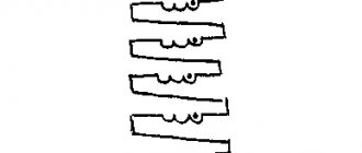
Why is the transformer magnetic circuit made of separate sheets of electrical steel?
The magnetic core is the structural basis of the transformer. It serves to conduct the main magnetic flux. To reduce the magnetic resistance along the path of this flow and, consequently, reduce the magnetizing current, the magnetic circuit is made of special electrical steel.
Interesting materials:
How to make animation in a power point presentation? How to make an animated ava in Telegram? How to make an animated picture in Photoshop? How to make an animated avatar on Steam? How to do anonymous voting in Among AS? How to make anonymous questions on Insta 2022? How to make an antenna in the game Bearded Man 3? How to make coffee flavoring? How to make an avatar on YouTube on your phone? How to make an auto-dial on MTS?
Application of transformers
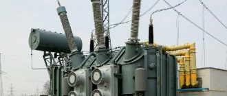
When transmitting electricity over long distances, quite large losses can occur due to heating of the wires. To avoid such a negative phenomenon, transformers are repeatedly used. Initially, the voltage at the power plant is increased accordingly with a significant decrease in current. After the energy passes through the power lines, before delivering the current to the consumer, the voltage is reduced to an acceptable level (220 V) using transformers.
Since three-phase current flows in power line networks, groups of 3 single-phase transformers connected in a star or triangular circuit are used to transform it. Three-phase transformers with a single magnetic core are also used. The equipment has high efficiency. Due to this, a large amount of heat is released. Therefore, powerful transformers are placed in containers filled with special oil.
Powerful power transformer
Various electrical appliances require power supply at a certain voltage level. To do this, transformers with the required characteristics are built into their housings. High-frequency pulse transformers are used to power modern radio engineering and electronic devices.
Transformers are the basis of control and measuring devices. The point of using such devices is to safely transmit the shape of the voltage pulses of the electrical circuit under study. For example, instrument transformers are used in diesel generator systems with medium power currents (up to 1 megawatt).
Matching transformers are used when connecting devices with low resistance to electronic stages with high input or output resistance values. An example would be connecting an audio amplifier to speakers that have very low impedance.
Additional Information. The amount of energy losses in a transformer directly depends on the quality of the electrical steel core. Minimal losses due to heating, hysteresis and eddy currents occur where the cores are assembled from a large number of sections.
Main properties and characteristics
The steel used for transformers is stainless, magnetic and has sufficient permeability. It is so popular in the production of electrical equipment due to the fact that it has high electromagnetic characteristics and loses a minimal amount of energy as a result of sterility.
Various elements for transformers and other electrical equipment are made from metal. It is also ideal for creating magnetic wires.
Transformer cores cannot do without this special type of steel because the material contributes to a higher resistivity. This allows less power to be lost from eddy currents. This problem usually affects the cores of electrical equipment. Thanks to its use, excessive heating of the core does not occur.
To reduce losses from eddy flows, reduce the thickness of the plate. Therefore, the steel thickness should be 0.5 mm at a frequency of 50 Hz. If the device operates at a higher frequency, then it is necessary to make a core from sheets of 0.1-0.2 mm.
Metal helps reduce magnetization reversal losses. This is another reason for the popularity of electrical steel for transformer core production.
Since losses and the process of cyclic magnetization reversal can be reduced by adding silicon to the metal, alloys with a high content of this element are called transformer steel. Thanks to the application, it was possible to reduce losses by a third. This also makes it possible to reduce the mass of the transformer by 10% and metal consumption by 20%.
Electromagnetic steel is used in almost all electromechanical products due to its unique properties.
What is the magnetic core of a transformer and why is it needed?
The magnetic circuit or core of the transformer allows voltage to be converted more efficiently, while reducing losses. For the manufacture of cores, special ferromagnetic steel is used.
Types of transformer cores
According to their structure, cores are divided into:
- rod;
- armored;
- toroidal.
The rod core has the shape of the letter P. The windings are mounted on the rods, and the rods themselves are connected by a yoke. This design of the magnetic circuit makes it easy to inspect and repair the windings. Therefore, this type is typical for medium and powerful transformers.
W-shaped armor core The windings are located on the central rod. Armor transformers are more difficult to manufacture. And repairing the windings in them is not as easy as in rod ones.
The toroidal core has the shape of a ring with a rectangular cross-section. The windings are wound directly onto it. Therefore, this type of core is considered the most energy efficient.
a – rod core, b – armor core, c – toroidal core.
Application
Transformer steel is used to make important transformer components. Its popularity is associated with increased properties due to the addition of silicon to the composition.
Rod magnetic circuit
This element is a rod on which windings and yokes are placed to complete the magnetic circuit. They are always made laminated. This element has a simpler design than the armor rod and allows you to obtain the necessary insulation for the windings.
Rod magnetic cores are necessary for powerful transformers, since they have half a winding on each rod. Devices that have a rod magnetic core have a low magnetic leakage flux, less wire consumption and a large winding cooling surface.
Armored
Armored magnetic cores are most suitable for low power ratings. This applies to devices producing from one to several tens of volt-amperes. They operate when the voltage level does not exceed 1000 V and the power supply frequency is 50 or 400 Hz. Transformers with an armored magnet rod differ from rod transformers in their lower power density per unit volume and weight. But their main advantage is cost.
Armored magnetic circuits are distinguished by rectangular rods located in a horizontal position; rectangular windings are located on them.
The armored magnetic circuit has a number of design advantages. When using it, you will only need one set of windings, which contains a yoke to protect against negative environmental factors.
Specifications
An important characteristic is transformation ratios. They show the dependence of the output voltage on the ratio of turns in the windings. The transformation coefficient is the basic parameter in the calculation.
Another important characteristic of a transformer is its efficiency. In some devices this figure is 0.9 – 0.98, which characterizes insignificant losses of magnetic stray fields. Power P depends on the cross-sectional area S of the magnetic circuit. Based on the value of S, when calculating the parameters of the transformer, the number of turns in the coils is determined: W = 50 / S.
In practice, power is selected based on the expected load, taking into account losses in the core. The power of the secondary winding is Pн = Un× Iн , and the power of the primary coil is Pс = Uс × Iс . Ideally, Pn = Pc (if we neglect losses in the core). Then k = Uс / Un = Iс / Iн , that is, the currents in each of the windings have an inversely proportional dependence on their voltages, and therefore on the number of turns.
Transformers price
The price of a transformer varies widely and depends on many factors. This takes into account the type and purpose, power and other electrical parameters. The cost of devices is reflected in the complexity of production and the materials used. Protection and other features are also important.
A transformer from a well-known manufacturer cannot be cheap. However, the buyer can be sure that the device he purchased fully complies with the specified characteristics, will not fail the first time it is turned on, and is guaranteed to work out its intended life.
High-voltage transformers can be assessed by their power, that is, if the power of a transformer is 63 MW (63,000 kVA), then it costs about 63 million rubles, but this is an approximate estimate .
Video: How to check the health of a transformer
Principle of operation
The operating principle of current transformers is based on the law of electromagnetic induction. Voltage from the external network is supplied to the power primary winding with a certain number of turns and overcomes its total resistance. This leads to the appearance of a magnetic flux around the coil, captured by the magnetic circuit. This magnetic flux is located perpendicular to the direction of the current. Due to this, losses of electric current during the conversion process will be minimal.
When the turns of the secondary winding, located perpendicularly, intersect, the electromotive force is activated by the magnetic flux. Under the influence of the EMF, a current appears that is forced to overcome the total resistance of the coil and the output load. At the same time, a voltage drop is observed at the output of the secondary winding.
Transformer steel composition
The material is made not only from silicon, but also an alloy with iron. The addition of this element causes the force coefficient to increase and the electrical power resistivity to increase when compared to grades without silicon.
If you add a certain amount of silicon to the composition, this will lead to a decrease in the individual weight of iron oxides.
According to the chemical composition, this material can be classified as an alloy metal due to the presence of silicon in an amount of up to 0.5%.
In transformer iron, the addition of foreign impurities is in the range of 3-4.5%.