Material used
There are no strict recommendations as to what alloy the steel elbow should be made of; GOST allows the use of various ferrous and corrosion-resistant steels. The raw material for basic products is predominantly low-alloy steel. The most popular brands are 09G2S, St20 and others.
If the product will work in highly loaded lines, it is better to use high-alloy steel (for example, 12ХН2А or 20G), as well as for work at high temperatures. And when the reinforcement comes into direct contact with chemically active substances, stainless steel alloys are chosen as raw materials: AISI 201, AISI 316 and others.
Galvanized variations of bends are also in demand on the market. For their production, a ready-made galvanized steel pipe is used, but its coating may be damaged during storage or transportation of the final product. Therefore, a newly manufactured elbow is often galvanized.
Production process
Depending on future operating conditions, choose one of five production methods:
- hot stamping (hot pressing);
- hot deformation;
- mechanical processing (bending);
- electric welding;
- combined technology (stamp welding).
With the hot-deformed method, the finished seamless pipe is cut into pieces of the required length, which are heated to +1000...+1100℃ (more precisely, the temperature is selected based on the steel grade used) in a hearth furnace or in another way and sent to a hydraulic press with a horn-shaped core. Each diameter has its own core. Then the product is sent for calibration, and its edges are trimmed on a special machine. The result of the work is seamless hot-deformed bends. This is the most expensive product in its class, because its production is the most labor-intensive and energy-consuming compared to analogues. However, the operational potential of these modifications is higher.
The hot stamping method is also carried out after preheating the workpieces. They are sent to a two-strand oval die, where they are given the appearance of an elbow with an elliptical cross-section. To prevent the stamp from damaging the edges of the future bend, a metal liner is driven into the workpiece to increase its rigidity. After leaving the oval die, the semi-finished product is sent to the molding die, where its shape is adjusted, turning it from oval to round. The final processing is carried out in a calibration stamp. If a bend with a diameter of more than 100 mm is made using this technology, the final molding is preceded by another operation - stretching the back. This is how seamless hot-stamped variations are produced.
In mechanical technology, a pipe bending machine is used; the operation can be carried out in a cold (more often) or hot (less often) version. Bending equipment can be automatic or manual. The fundamental difference between this technology and previous options is that the pipe is bent without preliminary cutting into individual products: first it takes the form of a snake, and then it is cut into segments. The output is bent bends, also without seams.
If the electric welding method is chosen, two or more closed ring parts of small height are first made (they are cut from a solid pipe or formed from tape). Then they are welded into a single piece by applying a girdle seam. This is how welded versions of products are produced; they are the most economical and practical among all, and their production takes the least amount of time.
With combined technology, stamping equipment produces two identical semicircular parts that mirror each other. The halves are combined and welded into a finished product, applying two parallel seams. These are stamp-welded modifications of fittings.
Materials and production methods
Steel bends are made from alloy, stainless, corrosion-resistant or carbon steel. Chrome-plated, nickel-plated and galvanized products with increased resistance to corrosion processes are produced. The material of manufacture influences the scope of application of the bends.
Household communications that do not have contact with aggressive environments are made of carbon steel . If the system contains chemically active substances, then bends made of stainless or alloy steel are used.
Alloyed bends are used at temperatures from −60 to +40 °C with pressures up to 7.4 MPa, which allows them to be installed on pipelines in cold climatic zones. Stainless steel products are intended for pipeline systems transporting hot, acidic, and alkaline media. They are resistant to corrosion.
Galvanized elbows are a common type of product made from galvanized steel. They are able to withstand high pressure and transport aggressive media.
Bends vary in manufacturing method. Highlight:
- Steeply curved.
- Stamp-welded.
- Bent.
- Welded sector/sectional.
- Chiseled.
Classification
The above division - hot-deformed, hot-stamped, bent, welded, stamp-welded - is the main classification of products. Sometimes, when describing products, they operate with other parameters of the fittings: sector options (obtained by electric welding) and smooth (all others). Steeply curved bends are also distinguished - these are those that have a small diameter. They are made mainly by stamping and bending. If the pipeline is not required to be compact, the outlet fittings for it will most often be stamped or welded; they are large in size.
There is another classification of the product: 2D and 3D. This parameter characterizes the ratio of the bend radius to the internal diameter of the product. In 2D these two values are approximately the same; in 3D the turning radius is one and a half times larger than the diameter. This designation can also look like: R-1.5D (this is a 3D type) or R-1D (a 2D option).
Marking
The main parameter characterizing steel bends is DN (DN in some documentation). This is their nominal diameter, or nominal diameter, the main criterion for choosing the exact model of the product when installing it in a pipeline and matching it with adjacent sections of the pipeline. DU must be indicated in the product designation.
Another important value is the wall thickness, since the elbow must fit perfectly into the pipeline line. The diameters of steel bends and wall thickness are standardized and correspond to the size range of pipes used today in everyday life and in production.
According to the angle of rotation of the knees, they are divided into models designed for an angle of 15, 30, 45, 60, 90 degrees. This value is also indicated in the designation.
An example of a short marking is 45° 38x2 09G2S, where:
- 45° — rotation angle;
- 38 – internal diameter, mm;
- 2 – thickness of its wall, mm;
- 09G2S – steel used.
Full marking of the product may also include length, GOST or other regulatory document according to which production was carried out, brand or identification number of the manufacturer, batch number.
The designation is applied to the product by embossing, paint or a sticker/label.
Steeply curved bends type 3D
STEEP BENDS TYPE 3D with an angle of 45o, 60o, 90o, 180o (GOST 17375-2001 ISO 3419-81)
This standard applies to seamless welded bends made of carbon and low-alloy steel type 3D with R approximately 1.5 DN, made from pipes using stamping methods or broaching along a horn-shaped core.
Bends are used for pipelines for various purposes, including those under the control of regulatory authorities, with PN(Pу) up to 16 MPa
and temperatures from
-70°C
to
+450°C
in accordance with the design and (or) design documentation, in which the conditions of use (operation) of parts are established based on the results of strength calculations, taking into account all external and internal force influences, properties transported by pipeline of substances and the environment, estimated service life and (or) resource, frequency and scope of routine maintenance and repairs, requirements of this standard, norms and rules of supervisory authorities and other regulatory documents for the design, construction and operation of pipelines.
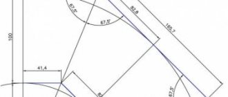
The design and dimensions of the bends must correspond to those indicated in the figure and tables (versions 1 and 2).
BENDS EXECUTION 1 45°, 90°, 180°
| DN | D mm | t mm | F=R mm | H mm | C mm | B mm | Weight with angle, kg | ||
| 45° | 90° | 180° | |||||||
| 15 | 21,3 | 2,0 3,2 4,0 | 28 | 14 | 56 | 38 | 0,02 0,03 0,04 | 0,04 0,06 0,07 | 0,08 0,12 0,14 |
| 20 | 26,9 | 2,0 3,2 4,0 | 29 | 14 | 58 | 43 | 0,03 0,04 0,06 | 0,06 0,08 0,10 | 0,11 0,17 0,20 |
| 25 | 33,7 | 2,3 3,2 4,5 | 38 | 18 | 76 | 56 | 0,05 0,08 0,09 | 0,11 0,16 0,19 | 0,21 0,32 0,38 |
| 32 | 42,4 | 2,6 3,6 5,0 | 48 | 23 | 96 | 69 | 0,10 0,13 0,17 | 0,19 0,26 0,35 | 0,39 0,52 0,60 |
| 40 | 48,3 | 2,6 3,6 5,0 | 57 | 29 | 114 | 82 | 0,13 0,18 0,24 | 0,26 0,36 0,47 | 0,53 0,72 0,95 |
| 50 | 60,3 | 2,9 4,0 5,6 | 76 | 35 | 152 | 106 | 0,25 0,33 0,50 | 0,50 0,67 0,89 | 0,99 1,30 1,80 |
| 65 | 76,1 | 2,9 5,0 7,1 | 95 | 44 | 190 | 133 | 0,40 0,72 0,90 | 0,79 1,50 1,80 | 1,60 2,90 3,60 |
| 80 | 88,9 | 3,2 5,6 8,0 | 114 | 51 | 228 | 159 | 0,60 1,00 1,40 | 1,20 2,10 2,80 | 2,40 4,10 5,70 |
| 100 | 114,3 | 3,6 6,3 8,8 | 152 | 64 | 304 | 210 | 1,20 2,00 2,80 | 2,40 4,00 5,40 | 4,70 8,00 11,00 |
| 125 | 139,7 | 4,0 6,3 10,0 | 190 | 79 | 380 | 260 | 2,00 3,10 4,80 | 4,00 6,20 9,60 | 8,00 12,00 19,00 |
| 150 | 168,3 | 4,5 7,1 11,0 | 229 | 95 | 457 | 313 | 3,20 5,10 7,70 | 6,50 10,00 15,00 | 13,00 20,00 31,00 |
| 200 | 219,1 | 6,3 8,0 12,5 | 305 | 127 | 610 | 414 | 8,00 9,90 14,00 | 16,00 20,00 31,00 | 32,00 40,00 61,00 |
| 250 | 273,0 | 6,3 10,0 | 381 | 159 | 762 | 518 | 12,00 19,00 | 25,00 39,00 | 50,00 78,00 |
| 300 | 323,9 | 7,1 10,0 | 457 | 190 | 914 | 619 | 20,00 28,00 | 40,00 56,00 | 80,00 111,00 |
| 350 | 355,6 | 8,0 11,0 | 533 | 222 | 1066 | 711 | 24,00 39,00 | 57,00 78,00 | 114,00 156,00 |
| 400 | 406,4 | 8,8 12,5 | 610 | 254 | 1220 | 813 | 41,00 58,00 | 82,00 117,00 | 165,00 234,00 |
| 450 | 457,0 | 10,0 | 686 | 286 | 1372 | 914 | 59,00 | 119,00 | 237,00 |
| 500 | 508,0 | 11,0 | 762 | 318 | 1524 | 1016 | 81,00 | 162,00 | 323,00 |
| 600 | 610,0 | 12,5 | 914 | 381 | 1828 | 1219 | 133,00 | 266,00 | 531,00 |
| 700 | 711,0 | — | 1067 | 444 | 2134 | 1422 | — | — | — |
| 800 | 813,0 | — | 1219 | 507 | 2238 | — | — | — | — |
| 900 | 914,0 | — | 1372 | 570 | 2744 | — | — | — | — |
| 1000 | 1016,0 | — | 1524 | 634 | 3048 | — | — | — | — |
| Notes 1. Weight is for reference only. 2. Bends with an angle of 60° of version 1 are not provided. | |||||||||
BENDS DESIGN 2 45°, 60°, 90°, 180°
| DN | D mm | t mm | F=R mm | W mm | H mm | C mm | B mm | Weight with angle, kg | |
| 90° | |||||||||
| 25 | 32 | 2,0 2,5 3,0 3,5 | 38 | 22 | 18 | 76 | 56 | 0,1 0,2 0,2 0,2 | |
| 32 | 38 | 2,0 2,5 3,0 3,5 4,0 | 48 | 28 | 23 | 96 | 69 | 0,2 0,2 0,2 0,3 0,3 | |
| 40 | 45 | 3,0 3,5 4,0 5,0 | 60 | 35 | 25 | 120 | 83 | 0,3 0,4 0,4 0,5 | |
| 50 | 57 | 2,5 3,0 3,5 4,0 4,5 5,0 5,5 6,0 | 75 | 43 | 80 | 150 | 104 | 0,4 0,5 0,6 0,7 0,7 0,8 0,9 1,1 | |
| 65 | 76 | 3,0 3,5 4,0 4,5 5,0 5,5 6,0 7,0 8,0 | 100 | 57 | 41 | 200 | 138 | 0,8 1,0 1,1 1,3 1,4 1,6 1,7 2,0 2,2 | |
| 80 | 89 | 3,0 3,5 4,0 4,5 5,0 5,5 6,0 7,0 8,0 | 120 | 69 | 50 | 240 | 165 | 1,2 1,4 1,5 1,7 1,9 2,1 2,3 2,7 3,0 | |
| 100 | 102 | 3,5 4,0 4,5 5,0 6,0 7,0 8,0 9,0 10,0 | 150 | 87 | 62 | 300 | 201 | 2,1 2,4 2,6 2,9 3,4 3,9 4,5 5,0 5,5 | |
| 100 | 108 | 3,5 4,0 4,5 5,0 6,0 7,0 8,0 9,0 10,0 | 150 | 87 | 62 | 300 | 204 | 2,2 2,5 2,8 3,1 3,6 4,1 4,7 5,3 5,8 | |
| 100 | 114 | 3,5 4,0 4,5 5,0 6,0 7,0 8,0 9,0 10,0 | 150 | 87 | 62 | 300 | 207 | 2,2 2,6 2,9 3,3 3,8 4,4 5,0 5,7 6,1 | |
| 125 | 133 | 3,5 4,0 4,5 5,0 6,0 7,0 8,0 9,0 10,0 11,0 12,0 | 190 | 110 | 79 | 380 | 257 | 3,3 3,8 4,3 4,8 5,7 6,5 7,4 8,2 9,1 10,0 11,0 | |
| 150 | 159 | 4,0 4,5 5,0 6,0 7,0 8,0 9,0 10,0 11,0 12,0 13,0 14,0 | 225 | 130 | 93 | 450 | 305 | 5,4 6,1 6,7 8,1 9,4 11,0 12,0 13,0 14,0 16,0 17,0 18,0 | |
| 150 | 168 | 4,0 4,5 5,0 6,0 7,0 8,0 9,0 10,0 11,0 12,0 13,0 14,0 | 225 | 130 | 93 | 450 | 305 | 5,6 6,4 7,1 8,5 9,8 11,2 12,5 14,0 15,0 16,0 17,5 19,0 | |
| 200 | 219 | 5,0 6,0 7,0 8,0 9,0 10,0 11,0 12,0 13,0 14,0 15,0 16,0 17,0 18,0 | 300 | 173 | 124 | 600 | 410 | 13,0 15,0 17,0 20,0 22,0 25,0 27,0 29,0 32,0 34,0 37,0 39,0 42,0 44,0 | |
| 250 | 273 | 6,0 7,0 8,0 9,0 10,0 11,0 12,0 13,0 14,0 15,0 16,0 17,0 18,0 20,0 22,0 | 375 | 217 | 155 | 750 | 512 | 23,0 27,0 31,0 35,0 39,0 43,0 46,0 50,0 54,0 58,0 61,0 66,0 70,0 78,0 85,0 | |
| 300 | 325 | 7,0 8,0 9,0 10,0 11,0 12,0 13,0 14,0 15,0 16,0 17,0 18,0 20,0 22,0 24,0 26,0 28,0 | 450 | 260 | 186 | 900 | 613 | 39,0 45,0 50,0 56,0 61,0 66,0 72,0 77,0 82,0 87,0 92,0 96,0 107,0 118,0 130,0 141,0 150,0 | |
| 350 | 377 | 9,0 10,0 11,0 12,0 13,0 14,0 15,0 16,0 18,0 20,0 22,0 24,0 26,0 28,0 30,0 32,0 | 525 | 303 | 217 | 1050 | 714 | 68,0 75,0 83,0 90,0 97,0 104,0 112,0 119,0 133,0 147,0 161,0 175,0 188,0 201,0 214,0 228,0 | |
| 400 | 426 | 8,0 9,0 10,0 11,0 12,0 13,0 14,0 15,0 16,0 17,0 18,0 20,0 22,0 24,0 26,0 28,0 30,0 32,0 34,0 | 600 | 346 | 248 | 1200 | 813 | 78,0 87,0 97,0 107,0 117,0 126,0 135,0 145,0 154,0 164,0 173,0 192,0 210,0 230,0 249,0 268,0 286,0 309,0 324,0 | |
| 500 | 530 | 9,0 10,0 11,0 12,0 13,0 14,0 15,0 16,0 17,0 18,0 20,0 22,0 24,0 26,0 28,0 30,0 32,0 34,0 36,0 | 750 | 433 | 310 | 1500 | 1015 | 138,0 153,0 168,0 183,0 198,0 212,0 227,0 242,0 256,0 270,0 298,0 327,0 356,0 385,0 413,0 440,0 467,0 494,0 520,0 | |
| 600 | 630 | 9,0 10,0 11,0 12,0 13,0 14,0 15,0 16,0 17,0 18,0 20,0 22,0 24,0 26,0 28,0 30,0 32,0 | 900 | 519 | 373 | 1800 | 1215 | 198,0 219,0 245,0 261,0 282,0 302,0 324,0 345,0 366,0 387,0 429,0 471,0 513,0 554,0 595,0 636,0 678,0 | |
| 700 | 720 | 9,0 10,0 11,0 12,0 13,0 14,0 15,0 16,0 17,0 18,0 20,0 22,0 24,0 26,0 28,0 30,0 32,0 | 1000 | 577 | 404 | 2000 | 1360 | 248,0 275,0 302,0 329,0 356,0 383,0 410,0 436,0 462,0 489,0 542,0 595,0 647,0 698,0 750,0 801,0 852,0 | |
| 800 | 820 | 9,0 10,0 11,0 12,0 13,0 14,0 15,0 16,0 17,0 18,0 20,0 22,0 24,0 26,0 28,0 30,0 32,0 | 1200 | 693 | 485 | 2400 | 1610 | 339,0 376,0 413,0 450,0 487,0 524,0 561,0 598,0 636,0 670,0 743,0 815,0 887,0 956,0 1030,0 1101,0 1171,0 | |
| Notes 1. Weight is for reference only. 2. The weight of bends with an angle of 60° and 45° is 1.5 and 2 times less, respectively, and that of bends with an angle of 180° is 2 times more than indicated. | |||||||||
LEGEND
90° elbow, version 1, D = 139.7 mm, t = 4.0 mm, made of TS4 steel: Elbow 90-1-139.7×4-TS4 GOST 17375-2001
bend with an angle of 45°, version 2, D = 159 mm, t = 4.0 mm, tв = 6.0 mm from steel grade 20: Bend 45-159x4/6 GOST 17375-2001
where tв is the wall thickness in non-end sections.
bend with an angle of 90°, version 2, D = 57 mm, t = 5.0 mm, made of steel grade 09G2S: Bend 90-57×5-09G2S GOST 17375-2001
the same, for pipelines controlled by supervisory authorities: Branch P90-57×5-09G2S GOST 17375-2001
According to GOST, bends are divided by steel grade in accordance with the table:
| Execution of retraction | Steel | |
| brand | standard | |
| 1 | TS4, TS9, TS10, TS18, TS32, TS34, TS37, TS43 | ISO 9329/1, ISO 9329/2, ISO 9329/3 |
| P5, P9, P18, P32, P34, P43 | ISO 9328/1, ISO 9328/2, ISO 9328/3 | |
| E24-1, E24-2 | ISO 3183 | |
| 2 | 10 | GOST 1050 |
| 20 | TU 14-3-460 | |
| 10G2 | GOST 4543 | |
| 20YuCh | TU 14-3-1652, TU 14-3-1745 | |
| 15GS | TU 14-3-460, TU 14-3-420 | |
| 09G2S, 16GS, 17GS, 17G1S, 10G2S1 | GOST 19281 | |
Stainless steel bends are produced from the following steel grades, the quality is determined by GOST 17375-2001:
- AISI 304, TP 304, 08Х18Н10, 12Х18Н9, 1.4307, 1.4301, TP 304L, AISI 304L, 03Х18Н11, 02Х18Н11 -
AISI 321, 12Х18Н10Т, TP 321, 1.4878, 1.45 41, 12Х18Н12Т, 12Х18Н10Т, 08Х18Н12Т, 08Х18Н10Т, 03Х18Н10Т, F 321, WP 321 - AISI 316, AISI 316L, TP 316, 1.4401, TP 316L, 1.4404, 03Х17Н14М3, 03Х17Н13М3, 03Х17Н13М2, TP 316LUG
Please check with specific manufacturers for specific standard sizes of bends for a specific steel grade. The designation can also be arbitrary, for example:
Steeply curved bend 45 89x3.0 12Х18Н10Т GOST 17375-01
.
Related documents:
— GOST 8946-75 — Pass-through angles, cast iron — GOST 22793-83 — Bent elbows to Ru St. 10 to 100 MPa - GOST 30753-2001 - Steeply curved bends type 2D
Purpose and scope
This representative of pipeline fittings connects individual sections of the pipeline into a single line, simultaneously setting the movement of the transported medium to the desired vector if the pipeline needs to change its direction or overcome some obstacle. Also, with the help of bends, pipes are removed from underground communication channels and placed on overpasses. They can be used to form compensators - units that perceive and compensate for the impact of unfavorable factors on the pipeline:
- spatial movements;
- shock and vibration loads;
- temperature deformations;
- displacements of soil and supports.
Steel elbows are in high demand for the construction of main and auxiliary process pipelines in many industries: from food to mining and metallurgy. They are also used in the oil and gas industry, mining, and other areas of the mining industry. The following can move through pipelines into which a steel outlet is integrated:
- water – drinking and technical, pure and with impurities, cold and heated;
- process fluids;
- liquid food and medicine;
- oil and its products, including fuels and lubricants;
- atmospheric air, natural gas and other gaseous substances;
- steam and steam-water mixture;
- mixed environments.
The fittings are installed in gravity and pressure pipelines and can be used at enterprises in the energy sector and other critical facilities. The largest consumer of such products is the housing and communal services sector - there they are used in household water supply systems, gas supply lines, sewer systems, and heating circuits.
Which outlet should I choose?
It depends on the purpose for which it is purchased. If these are large diameter pipes, then it is better to use sectional bends.
Sectional welded bends
As mentioned above, steel bends are used in a huge number of areas. These include both household and industrial sectors.
Characteristics
Fittings that are designed for industrial use can withstand a wide range of temperatures, from -60 to 450 degrees.
Parts of this type must be protected from substances that can harm them at the chemical level (acids, alkalis). The bends are designed for a pressure of 16 MPa. The diameter can vary from 32 to 426 mm.
Steel bends are used in the energy industry.
Key Features
The products are characterized by high performance characteristics. Among their advantages is resistance to the effects of almost all unfavorable external factors of any origin: biological, atmospheric, chemical, man-made. In addition, the list of product advantages includes:
- the ability to smoothly rotate the pipeline axis;
- being integrated into the main line using electric welding, they provide maximum connection reliability;
- are immune to temperature fluctuations, since steel has a low coefficient of thermal expansion;
- can be used in harsh operating conditions;
- have high mechanical strength;
- absolutely gas-tight.
Steel bends successfully withstand high operating pressures and are capable of operating in conditions of critically high and low temperatures. They are resistant to excess ambient moisture, reliable, and operate for a long time.
Advantages of steel bends
Bends play an important role in the pipeline system, allowing it to be changed in direction and increasing its strength. The main advantages and purpose of steel bends:
- Ensures smooth rotation of the pipeline.
- Possibility of operation in various conditions - they have high strength characteristics.
- Resistant to temperature changes.
- Long service life.
The production of bends is regulated by various standards. Products are manufactured in accordance with OST 34-10-752 (sectoral bends for power systems), OST 36-21 (welded sectional bends), GOST 30753 (seamless bends), GOST 17375 (steeply curved bends), etc.
Installation rules
Installation of bends on pipelines is carried out using the welding method. This is a labor-intensive process that requires certain skills from the welder. When welding, it is necessary to constantly monitor the alignment of the internal surfaces and edges of the parts being welded. To do this, alignment is performed using a special vice (for small diameter pipelines) or rotators. The latter are used for welding large-diameter pipes and guarantee strong adhesion of the elements to each other during the welding process.
When welding bends and pipelines, you must follow the installation rules:
- Before installation, you need to check the availability of accompanying and regulatory documentation and study the instructions.
- Welding work is carried out only by trained specialists who have the appropriate permits and regulations.
- Work is carried out only in special protective clothing with a mask.
- No foreign objects are allowed in the workplace. There must be a fire extinguishing agent and ventilation.
- Welded edges of parts must be prepared. Products are not allowed to have defects or irregularities, chips, cracks, delaminations, etc.
- During the welding process, it is necessary to control the specified mode, selected based on the characteristics of the materials being welded.
Manual electric arc welding is carried out at direct current in two stages.
Round ducts
Round-section air ducts are divided into spiral-wound and straight-seam. They can be used in general exchange, supply and exhaust ventilation, as well as in pneumatic transport and aspiration systems.
Let's look at the advantages and disadvantages of each of these types.
| Options | Spiral-wound air ducts | Straight-seam air ducts |
| Production time | + | _ |
| Ease of production | + | _ |
| Manufacturing cost | + | _ |
| Application in aspiration and pneumatic transport systems | _ | + |
| Setting the system to vacuum | _ | + |
| Rigidity | _ | + |
| Strength | _ | + |
| Wear resistance | _ | + |
| Cost calculation | + | _ |
Main components of round air ducts
Ventilation outlet 90⁰
Ventilation outlet 60⁰
Ventilation outlet 45⁰
Ventilation outlet 30⁰
Ventilation outlet 15⁰
For ordering there is a symbol: d - diameter (mm)
α - turning angle ° R - turning radius (mm)
When R=d - not specified R =1 xd In a standard bend, the turning radius is equal to its diameter. The radius, if necessary, can be any.
Go to the air duct catalog
Go
Round ventilation transition
Central Single-sided Offset
Used to narrow or widen the cross-section of the air duct. It is extremely difficult to do without such a product on site, since manufacturing the transition is quite a complex and lengthy process if done manually during installation.
When ordering, indicate small and large diameters. If the order is non-standard, then the length and offset (for offset transitions) are also indicated.
d1 - diameter (mm) d2 - diameter (mm)
When ordering a non-standard length, please indicate:
Length (mm) - L Offset (mm) - C
Round ventilation tee
First type:
Used to branch air flows. Sometimes, in order to save money, they order tie-ins instead of tees and make a branch on site, but this method takes more time in installation.
There is an ordering symbol:
d1 - diameter (mm) d2 - diameter (mm) L - length (mm) H - height (mm)
Any size ratio possible (subject to technical limitations)
Second type:
There is an ordering symbol:
d1 - diameter (mm) d2 - diameter (mm) L - length (mm) α - angle
Any size ratio is possible (subject to technological limitations).
Third type:
There is an ordering symbol:
d1 - diameter (mm) d2 - diameter (mm) d3 - diameter (mm) L - length (mm) α - angle
Any size ratio is possible (subject to technological limitations).
Fourth type:
Sometimes you have to make a branch of a rectangular section. This may be necessary, for example, to connect small rectangular distribution grids that are inserted into the channel.
There is an ordering symbol:
d - diameter (mm) H - height (mm) A×B - insert size (mm) n - flange: 20 (mm), 30 (mm), (without flange: 0) L - length (mm)
Any size ratio is possible (subject to technological limitations).
Round ventilation cross
For a standard part: H2 = H3 − 0.5d1 + 50 (mm)
If l > (d2 + d3) / 2 + 120 (mm), then it is possible to consider using two tees. Typically, such products are not ordered in advance, but are manufactured on site using tees.
There is an ordering symbol:
d1 - root diameter (mm) d2 - diameter (mm) d3 - diameter (mm)
Height (mm) — H2,H3 L — part length (mm) If l = 0, do not indicate l — distance between cut-ins (mm) α — angle between cut-outs from d3 to d2, °
Any size ratio is possible (subject to technological limitations).
Round ventilation nipple
Serves to connect air ducts of the same diameter to each other. The air ducts are inserted from different sides of the nipple in one simple movement. Without nipples, it can be extremely inconvenient to connect pipes, since you have to roll them (“make a flower”) and insert one into the other. It looks ugly and is inconvenient to do.
There is an ordering symbol:
d —diameter (mm)
Total length of ventilation nipple:
up to Ø 500 - 140 (mm) up to Ø 900 - 180 (mm) up to Ø 1250 - 200 (mm)
Round ventilation coupling
Connects shaped products and air ducts. Made from galvanized steel. become. Unlike a nipple, it is put on top of the parts to be fastened. For small diameters they are usually not used, but are cut from pieces of pipe, but for large diameters (more than 400mm) it can take much longer to cut the pipe on site, so it is more profitable to order them in advance.
There is an ordering symbol:
d—diameter (mm)
Each diameter corresponds to a certain coupling length L–mm. (See Appendix 1).
Round ventilation plug
It is the end element of the system to block the channel cross-section.
Required when ordering:
d—diameter (mm)
From 100 to 1250 mm.
It is also possible to choose any diameter and length and make it with a handle at the end.
Round ventilation duck
It is a shaped product and is used at the joints of multi-level air ducts. Can also be used at the junction of air ducts located to the left or right of each other. You can also get by using two bends of 30 or 45 degrees instead of a duck.
When ordering please indicate:
d1 - diameter (mm) d2 - diameter (mm) L - part length (mm) H - height (mm).
If d1= d2, then indicate one size
It is also possible to use any size (subject to technological limitations).
Throttle valve for round air ducts
Galvanized steel is used for production. It consists of a pipe, a canvas and a control sector. The so-called vane, located on the outside of the valve, is installed on the control unit. It can be rotated using the handle. The valve cross-section is closed at the required angle using a spatula. The blade is secured with a wing nut. Using a graduated scale, the angle of rotation is determined. Throttle valves are recommended for use on main lines or at air duct branch points.
The correct location and number of throttle valves is very important so that you can correctly balance the system and set the required flow rates for the branches.
Roof umbrella for round air duct
Protects the air duct from precipitation. Typically used on vertically installed exhaust pipes.
To order use:
d - diameter (mm) (from 100 to 710 mm)
D and height H depend on d.
Round ventilation insert
A shaped part installed in the walls of air ducts. Used instead of a tee to branch the flow. It takes a little longer to install than a tee, but is cheaper and allows you to install it anywhere.
There are three types:
- For installation in a rectangular duct or a round duct
- For connecting round ducts
- For corner ducts
When ordering please indicate:
d - diameter from 100 to 1250 mm I - length 40, 60, 80, 100 mm,
also for if necessary
H - height (not less than 50 mm) α - angle, °
It is also possible to use any size ratios (subject to technological limitations).
Roof passage unit for air ducts
It is used in places where ventilation shafts are installed on the roof. The main task of the passage unit is to seal the passage opening.
When ordering please indicate:
d – diameter 100 – 400 mm H – height (mm). α - angle °
It is also possible to use any size ratios (subject to technological limitations).
Round ventilation damper
Shut-off and control device. Made from thin sheet galvanized steel. They are divided into direct (in aspiration and pneumatic transport systems) and oblique (in general ventilation systems) dampers. In this case, the pressure in the system should not exceed 1000 Pa. The main function is to regulate the air flow.
Flexible round inserts for air ducts
Eliminate vibration when connecting high-power equipment, such as radial fans or air handling units, so that vibration noise is not transmitted into the duct system.
Use from 100 to 1600 mm.