Making bends from galvanized steel with your own hands
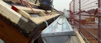
If you are interested in the question of how to make a galvanized pipe with your own hands, then you want to save on construction. Indeed, making homemade tin structures is a smart alternative to factory-made gutters, chimneys and ventilation hoods. This article will tell you how to practically do the work.
Material characteristics
Galvanized structures are made of tin. The material is sheet rolled steel with a thickness of 0.1 - 0.7 mm.
Products of complex shapes are formed from soft material
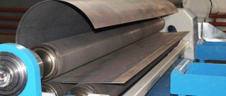
The production of sheets takes place on rolling machines, but the products obtained in this way require additional protection. Therefore, it is coated with a material that is resistant to corrosion. Ultimately, consumers receive a steel sheet with a width of 512-1000 mm, which has a micron coating of chromium, tin or zinc.
The product is characterized by plasticity, which allows the sheet metal to be processed manually. Moreover, if stiffening ribs are rolled onto the material, it is not inferior in strength to its steel counterparts. For these reasons, tinplate is used in the manufacture of products with complex shapes.
Required Tools
The soft and plastic material is easy to bend, so galvanized pipes are made using simple tools:
- Hand scissors for metal. With this tool you can effortlessly cut sheet metal, the maximum thickness of which is only 0.7 mm.
- Hammer with a soft striker. This role can be played by a wooden hammer or a metal tool with a rubber pad on the striking part.
To work you will need a wooden hammer
Note! A hammer with a metal striker is not suitable in this case. It can deform a thin sheet of galvanized sheet and ruin the product.
- Pliers. Despite its softness, it is impossible to bend thin metal with your hands.
In addition to tools, you will need equipment:
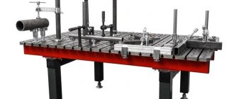
- A workbench used to mark and cut workpieces.
- A calibrating element in the form of a steel pipe with a diameter of 100 mm or an angle with sides measuring 75 mm.
Important! The calibrating elements should be rigidly fixed, since they are used to rivet the joining seam of future gutters or ducts.
In the process of marking workpieces, you cannot do without measuring tools - a metal ruler, tape measure, square or marker (a sharpened steel rod with a hardened end).
Making galvanized pipes with your own hands
The production of casings and cylinders from galvanized steel includes three stages:
- Preparatory. It starts with marking and ends with cutting out the finished “pattern”.
- Molding. At this time, the formation of a given profile of the chimney or ventilation duct occurs.
- Final. At this stage, the opposite edges of the workpiece are connected to each other.
Now let’s look in detail at the step-by-step production of galvanized pipes by hand.
Cutting out the workpiece
Tin can be easily cut with scissors
Take a sheet of galvanized sheet and make a sketch of the product. Next proceed as follows:
- Cut out the resulting measured piece of sheet on which you have drawn the outline of the product you need.
- Roll out a galvanized sheet on a flat area of the workbench. Measure the length of the box from the top edge and make a mark there.
- Take a square and draw a line from the length mark of the product perpendicular to the side edge of the sheet.
- Mark on the upper edge of the workpiece and the marked length line of the product the size of the perimeter of the ventilation duct or the circumference of the chimney cylinder.
Note! The actual circumference or perimeter must be increased by 15 mm to form joining edges.
- Connect the resulting marks at the top and bottom.
- Cut a “pattern” from the sheet by making a side and longitudinal cut.
On a note! To measure the circumference of a galvanized chimney pipe, use a tape measure or calculate it by the diameter of the product using a school geometric formula. To determine the perimeter, add up all sides of the box.
Formation of a profile
It is better to bend sheets with pliers
Now we begin to form the profile of the future structure.
- Mark a fold line along the workpiece (0.5 cm on one side, 0.5 cm twice on the other).
- Bend the folds at an angle of 90˚ to the plane of the workpiece, which was previously placed along the steel angle (its edge should coincide with the bend line of the fold).
- Deform the sheet using a hammer until it comes into contact with the second plane of the angle.
Important! The shape of the sheet should be changed gradually, slowly moving along the fold line. Do the job using pliers first.
- Make an L-shaped bend on a fold measuring 1 cm along a line of 0.5 cm parallel to the plane of the workpiece.
- Now start shaping the chimney body. Place the workpiece on the calibrating plane and tap the galvanized steel with a hammer until you get the profile of the desired shape. The folds should meet at the end.
Processing the butt seam
To crimp the butt seam, align the vertical folds. Fold the horizontal part of the L-shaped fold down so that it wraps around the vertical fold of the other edge of the structure. Bend the protruding “sandwich”, pressing it to the plane of the chimney.
The question of how to make a galvanized pipe yourself has been resolved. We wish you success!
: pipe manufacturing
Aspiration. — Product patterns
If this page loads slowly, its main images can be opened and viewed in the “Drawings, diagrams, site images” catalogue.
Cap - a cap made of galvanized sheet metal for a brick pillar
Choose any height “h”, or taking into account the dimensions of the finished pillar. It is sometimes useful to increase the planting dimensions “a” and “b” by 5 - 10 mm, depending on the quality of the masonry. The size “d” can be “estimated” with a tape measure directly on the pole, or calculated using the formula below.
* Place the pattern face up. Drill a hole Ф3.5 mm. Bend the stiffeners (15mm) down almost 90°. Bend all dotted lines at an angle of 90°. The bending of the lines should be done in a sheet bending machine, at least in a homemade one of two corners (it doesn’t take long to do).
Then the bend lines will be straight, clear, without dents, and the product will ultimately have an aesthetic appearance. If there is no sheet bender, then bend lines “a” and “b” as usual; bend lines “A” and “B” on a piece of angle No. 50 - 63 fixed on the edge of the workbench with the shelf facing up.
To bend plane A or B all at once, or almost all of it, use a 25x45 mm block (picket) 30-40 cm long.
Bend the edges along the lines “d” to the correct rectangular shape of the cap or umbrella. To do this, have a narrow mandrel: a 50mm corner with a cut flange, or a metal strip 1.5-2 mm thick attached to it, or even better, a saw blade.
Check the tight fit of the upper (closing) stiffener rib to the rear (rear) plane of the cap. Check again that the product is not distorted; Use a thin marker to mark the response hole (diameter 3.5 mm); punch, drill, and secure the assembly with a 3.2 mm rivet.
How to make a galvanized outlet with your own hands. How to make a pipe from tin – VentiSam
Home builders try to select the most budget-friendly options to solve problems. Therefore, the question of how to make a pipe from tin with your own hands is relevant for many amateur craftsmen. After all, a homemade pipe product made from tin can be compared with gutters or casings that are on the shelves in specialized stores.
Therefore, you need to learn in more detail the process of manufacturing a tin pipe that has characteristics similar to factory products.
Features of the source material
Before you start making a pipe from a sheet of metal, you should become more familiar with the material from which the pipe will be made and its features. To begin with, it is worth saying that this is a rolling type product, in other words, tin is a sheet of steel that has passed through the rollers of a rolling mill and has a thickness of 0.1-0.7 mm.
In addition to rolling operations, the technology for producing tin plates involves processing the finished rolled products to prevent the formation of corrosive processes. To do this, a layer of material is applied to the steel after rolling, which is not susceptible to corrosion.
The result of the performed actions is a steel sheet, the width of which can vary from 512 to 1000 mm, with a chrome or zinc coating.
The finished product is flexible, so tin can be easily processed by hand. At the same time, rolled stiffeners can be compared in strength to steel products.
This allows the use of tin in the manufacture of products of complex designs.
Required Tools
The list of tools and devices necessary for making a galvanized chimney pipe with your own hands is determined by the properties of tin, in particular softness and ductility. Processing this type of material does not require the special efforts required to work with sheet materials.
Therefore, when producing tin chimney pipes, the following set of tools is required:
- Scissors for cutting metal. This tool helps to cut sheet material into the required pieces without much difficulty, since the largest thickness of the sheet reaches 0.7 mm.
- Hammer with a soft striker. You can also use a wooden hammer, mallet, or a steel tool with a soft rubber grip. However, the latter option is used very carefully or not at all, since it can cause deformation of a thin sheet of tin and ruin the entire work.
- Pliers. With the help of this tool they solve the problem of how to bend a pipe made of tin, because it is steel, although thin, therefore it is impossible to bend it with your hands.
- Crafting table. This device is necessary when cutting material and when applying markings.
- Calibrating element. This can be a pipe product with a diameter of more than 10 centimeters, as well as a corner with edges of 7.5 centimeters. These elements must be well secured, since the joining seam will be riveted on their surface.
Instructions for making a tin pipe with your own hands
The production of tinplate products, including pipes, takes place in three stages:
- Preparatory work involves marking the workpiece and cutting it out of a sheet of tin.
- Forming involves shaping the profile of a pipe or other product.
- In the finale, the opposite edges of the workpiece are connected.
Preparatory stage
First, markings are applied to the sheet of tin, according to which the semi-finished product will be cut. In other words, the necessary part is cut from a certain sheet of tin, from which the contour of the future pipe will be formed. The marking process is carried out as follows: the sheet metal is laid out on a workbench and a segment equal to the length of the pipe is measured from the top edge. A mark is placed here with a marker.
Then, using a square, draw a line along this mark perpendicular to the side edge. Now along this line the circumference of the pipe, the same is done along the upper edge. In this case, about 1.5 cm is added on both edges to form the joining edges. The upper and lower marks are connected and the workpiece is cut out.
To determine the circumference, you can use a tape measure, or you can remember your school geometry course.
How to make a pipe body from tin
The purpose of this stage is to form the pipe profile. A line is drawn along the length of the workpiece at the bottom and top along which the folds will be folded.
In this case, 5 mm are measured on one side, and 10 mm on the other. The folds must be bent at an angle of 900. To do this, the workpiece is placed on a steel corner, aligning the bend line with the edge of the corner.
Hitting the edge with a mallet, bend it to the perpendicular side of the corner.
It is recommended to bend the product gradually, passing the hammer along the entire length. In this case, you can start bending using pliers.
Now, on the fold, the size of which is 10 mm, another fold of the fold is made to form a kind of letter G. In the process of bending the fold, you need to ensure that the upper bend is parallel to the workpiece, and its length is 5 millimeters. Therefore, when drawing a fold line, measure 0.5 cm once on one side, and 0.5 cm twice on the other side.
Having completed the molding of the folds, you can proceed to the formation of the pipe body. To do this, the workpiece sheet is placed on the calibrating element and begins to be tapped with a mallet or other suitable tool to obtain a profile of a certain shape. The workpiece first takes on a U-shape and then becomes round. In this case, the folds should join together.
Processing the seam joint
The final stage involves processing the joining seam, that is, crimping it. To do this, the upper part of the L-shaped fold is folded down, wrapping the edge of the other fold. The result should be a kind of sandwich located perpendicular to the pipe. To obtain a joining seam, you need to press the sandwich to the product.
For greater reliability, the joining seam is strengthened using rivets. However, do-it-yourself tin pipes using this joining method do not require additional reinforcement.
trubaspec.com
articles
If you are interested in the question of how to make a galvanized pipe with your own hands, then you want to save on construction. Indeed, making homemade tin structures is a smart alternative to factory-made gutters, chimneys and ventilation hoods. This article will tell you how to practically do the work.
Material characteristics
Galvanized structures are made of tin. The material is sheet rolled steel with a thickness of 0.1 - 0.7 mm.
The production of sheets takes place on rolling machines, but the products obtained in this way require additional protection. Therefore, it is coated with a material that is resistant to corrosion. Ultimately, consumers receive a steel sheet with a width of 512-1000 mm, which has a micron coating of chromium, tin or zinc.
The product is characterized by plasticity, which allows the sheet metal to be processed manually. Moreover, if stiffening ribs are rolled onto the material, it is not inferior in strength to its steel counterparts. For these reasons, tinplate is used in the manufacture of products with complex shapes.
Making galvanized pipes with your own hands
The production of casings and cylinders from galvanized steel includes three stages:
- Preparatory. It starts with marking and ends with cutting out the finished “pattern”.
- Molding. At this time, the formation of a given profile of the chimney or ventilation duct occurs.
- Final. At this stage, the opposite edges of the workpiece are connected to each other.
Cutting out the workpiece
Take a sheet of galvanized sheet and make a sketch of the product. Next proceed as follows:
- Cut out the resulting measured piece of sheet on which you have drawn the outline of the product you need.
- Roll out a galvanized sheet on a flat area of the workbench. Measure the length of the box from the top edge and make a mark there.
- Take a square and draw a line from the length mark of the product perpendicular to the side edge of the sheet.
- Mark on the upper edge of the workpiece and the marked length line of the product the size of the perimeter of the ventilation duct or the circumference of the chimney cylinder.
- Connect the resulting marks at the top and bottom.
- Cut a “pattern” from the sheet by making a side and longitudinal cut.
Formation of a profile
Now we begin to form the profile of the future structure.
- Mark a fold line along the workpiece (0.5 cm on one side, 0.5 cm twice on the other).
- Bend the folds at an angle of 90˚ to the plane of the workpiece, which was previously placed along the steel angle (its edge should coincide with the bend line of the fold).
- Deform the sheet using a hammer until it comes into contact with the second plane of the angle.
- Make an L-shaped bend on a fold measuring 1 cm along a line of 0.5 cm parallel to the plane of the workpiece.
- Now start shaping the chimney body. Place the workpiece on the calibrating plane and tap the galvanized steel with a hammer until you get the profile of the desired shape. The folds should meet at the end.
To crimp the butt seam, align the vertical folds. Fold the horizontal part of the L-shaped fold down so that it wraps around the vertical fold of the other edge of the structure. Bend the protruding “sandwich”, pressing it to the plane of the chimney.
The question of how to make a galvanized pipe yourself has been resolved. We wish you success!
: pipe manufacturing
How to make a galvanized pipe with your own hands: step-by-step instructions, calculation according to the diagram and drawing
Good day, dear guest!
The first sheet with galvanic coating came off the assembly line of one of the British factories back in 1867. True, at that time the metal was covered exclusively with gold and silver. But before the First World War, the production of parts with a protective layer of zinc began to be produced, and since then they have been incredibly popular.
This is not surprising - zinc extends the life of iron by 20-30 times. Products made of galvanized steel are durable, do not rust, and behave in everyday life no worse than stainless steel, although they are much cheaper.
In today’s article, I propose to pay more attention to this modest material and tell you how to make a galvanized pipe with your own hands.
Advantages and disadvantages of such a pipe
Galvanization is primarily steel, a material that has many undeniable advantages.
These include:
- Strength;
- Ability to withstand high temperatures;
- Excellent thermal conductivity;
- Low cost compared to other materials.
But without a protective coating, ferrous metal is susceptible to corrosion, quickly rusts and becomes unusable. Galvanizing successfully solved this problem. And, despite the fact that galvanized and steel pipes are the same in shape, the galvanized product has a number of advantages.
Additional advantages of galvanized products:
- Corrosion resistance, the ability to withstand negative environmental influences;
- Increased service life;
- Increased strength;
- Wide operating temperature range;
- High resistance to mechanical stress;
- Galvanized pipe can withstand high internal and external pressure;
- Simplicity and ease of installation;
- High resistance to fire;
- Zinc kills all pathogenic microorganisms;
- Galvanization is practically not inferior in quality to low-alloy stainless steel, but costs an order of magnitude less.
But, like any engineering solution, a galvanized iron pipeline is not ideal.
Disadvantages of the product:
- Not very attractive design;
- Expensive compared to conventional steel;
- Zinc complicates the welding process;
- Unlike plastic, if there are protrusions on the walls, it is almost impossible to ensure a smooth transition into structures made of galvanized pipes.
Make it yourself or order it
What is better, buy a galvanized sheet of the required thickness and bend the pipe yourself, or go to the store and buy a finished product?
Selection tips and approximate price
As usual, let's start with the price. A finished pipe with a diameter of 100 mm and a length of 3 meters will cost you and me about 500 rubles.
The cost of the material in this case is 150 rubles, the rest is labor costs and the seller’s markup.
What if you plan to organize an entire drainage system? You can see for yourself that you will have to overpay for finished products by 2.5-3 times. Making your own pipes will greatly ease the financial burden.
In addition, factory products have strictly defined dimensions, and sometimes it is difficult to choose the right one for your system. And the thickness of the finished pipe usually does not exceed 1 mm.
You should definitely remember that any factory-made product, unlike a home-made one, undergoes strict quality control control, has a perfectly round surface and a precision weld.
Whether a home master will be able to ensure compliance with all these conditions is far from certain.
Which material to choose
If you have decided to make the part yourself, you should start by choosing the material, in our case, a galvanized sheet of the required thickness.
What you need for work
After purchasing a sheet with the necessary characteristics, you should stock up on the necessary equipment.
Required tools:
- Metal scissors. Choose a convenient tool for cutting a wide sheet of metal;
- A hand jackhammer (also known as a mallet) with a rubber or wooden tip. The mallet should be hard, heavy, but without sharp edges;
- Steel pipe blank for molding the pipe body (“gun”). Its length is at least 1 meter, its diameter depends on the required diameter of the finished product;
- Ruler;
- Tool for marking galvanized steel (sharp metal rod);
- Crafting table. At the corner of the workbench there should be a metal corner, at least 1 m long. It will be used to bend the edges of the pipe, so it must be fastened very securely;
- Pliers.
Size calculation
A standard galvanized sheet sheet has dimensions of 1000x2000mm, or 1250x2500mm, although other cuts can be found.
The width of the workpiece is calculated using the formula:
L (circumference, also known as the width of the workpiece) = 2*3.14*R (R is the required pipe radius, mm).
Thus, to make a pipe with a diameter of 100 mm, you will need a blank with a width
2x3.14x50mm = 314mm.
To the resulting finishing length we add a bend of 15mm and get the required value for cutting -300mm.
An important point is that the width of the workpiece is not a constant value. On one side it is 330mm, on the other 340 (for a pipe with a diameter of 100mm). This is done for the convenience of subsequent installation of pipes with each other or with other elements of the system.
Drawing and diagram
Rice. 1. Pattern of a sheet for a pipe with a diameter of 100 mm.
The fold formation pattern is as follows:
Rice. 2
manufacturing
Check out useful videos on the topic.
Pipe making:
Inserting a pipe into a plane:
Expert advice
To make it easier to connect the finished pipe with other elements of the system, it is necessary to make a socket at the end of the product.
How to make a socket on a galvanized metal pipe
A bell is a technological extension designed for the convenience of installing communication elements with each other and inserting them into a plane. The socket on the finished pipe is made along a wide edge, using the method of flaring the edge to a depth of 15-20mm. In the factory, a special tool is used for flaring - a rolling cone.
At home, you can expand the edge of the pipe yourself using pliers. Ideally, install special rings—stiffening ribs—at the ends of the workpiece.
Fig.3. Flaring diagram:
Features of working with tin
Galvanized sheet metal is an inexpensive and reliable material. Its main feature is its small thickness (most often at home, a sheet with a thickness of 0.3 to 1 mm is used) and plasticity. Thanks to its softness, it is convenient to work with galvanizing and making the desired product yourself will not present much difficulty even for a novice tinsmith.
At the same time, despite the softness of the steel, the resulting seam seam is very reliable and can withstand significant mechanical stress.
Conclusion
The scope of application of galvanized pipes is extensive. They are used for drainage, chimneys, and ventilation systems, so the ability to make parts yourself will definitely not be superfluous.
Personally, I believe that any skill learned is always useful. That’s why I’m waiting for you in our group and communities. Lessons, training videos, expert advice - everything is there. Join us!
(3 5,00 of 5) Loading...
Welded sector bends
Welded sector (segment) bends are used to connect large-diameter pipes with a certain angle of rotation of the flow, operating under low pressure conditions. The angle of rotation of the welded elbow depends on the application and operating conditions of the part. Welded sector bends can be manufactured at different angles, but the most common sector welded bends have an angle of 30°, 45°, 60° and 90°. Today, in almost all construction of pipelines or heating mains, welded sector bends are used. In the figure below, you can see how welded sector bends schematically look:
Welded sector bends:
Welded sector bends are most often manufactured according to two standards: OST 36-21-77 (for oil pipelines) and OST 34 10.752-97 (for water and steam pipelines). Welded sector bends are made from a sheet of steel or pipe by manufacturing cone-shaped rings and then welding them into a bend (elbow). Such bends come from a diameter of 530 mm and above. A distinctive feature of welded bends is the price; as a rule, it is several times lower than the price of steeply curved seamless bends and stamp-welded bends of large diameters, this is due to the simple process of their manufacture.
The tables below indicate all types of welded sector bends according to OST 36-21-77 and OST 34 10.752-97 supplied by our company, as well as all the characteristics of these bends:
Bends according to OST 36-21-77
| Dimensions, mm | Conditional pressure Ru MPa | |||||||||||
| Du | Dн | R | L angled bends | N | s | non-aggressive | moderately aggressive | |||||
| sectors | half-sectors with an angle | |||||||||||
| 90° | 60° | 45° | 30° | 22°30’ | 15° | |||||||
| 500 | 530 | 750 | 750 | 432 | 310 | 201 | 260 | 200 | 130 | 7 8 10 12 | 1,6 (16) 2,5 (25) — — | 1,0 (10) — 1,6 (16) 2,5 (25) |
| 600 | 630 | 900 | 900 | 520 | 372 | 241 | 314 | 242 | 157 | 7 10 12 | 1,6 (16) 2,5 (25) — | 1,0 (10) 1,6 (16) 2,5 (25) |
| 800 | 820 | 1200 | 1200 | 694 | 496 | 322 | 424 | 327 | 212 | 8 10 12 14 | 1,6 (16) — 2,5 (25) — | 1,0 (10) 1,6 (16) — 2,5 (25) |
| 1000 | 1020 | 1500 | 1500 | 865 | 620 | 402 | 530 | 410 | 265 | 8 10 12 15 | 1,0 (10) 1,6 (16) — 2,5 (25) | 0,63 (6,3) 1,0 (10) 1,6 (16) — |
| 1200 | 1220 | 1800 | 1800 | 1040 | 745 | 483 | 638 | 493 | 319 | 9 12 15 | 1,0 (10) 1,6 (16) — | 0,63 (6,3) 1,0 (10) 1,6 (16) |
| 1400 | 1420 | 2100 | 2100 | 1210 | 870 | 564 | 744 | 576 | 372 | 10 14 | 1,0 (10) 1,6 (16) | 0,63 (6,3) 1,0 (10) |
In the following table you can see the mass of bends manufactured in accordance with OST 36-21-77:
| Dimensions, mm | Weight, kg | |||||||
| Du | S | angled bends | sectors | half-sectors with an angle | ||||
| 90° | 60° | 45° | 30° | 22°30’ | 15° | |||
| 500 | 7 8 10 12 | 109,1 124,4 154,7 184,7 | 72,7 83,8 102,9 122,9 | 56,0 63,8 79,3 94,6 | 36,2 41,2 51,2 61,0 | 36,0 41,0 50,9 60,7 | 27,8 31,6 39,2 46,7 | 17,9 20,3 25,2 29,9 |
| 600 | 7 10 12 | 155,9 220,9 265,2 | 103,9 147,4 176,0 | 80,1 113,6 135,6 | 51,8 73,3 87,5 | 51,6 73,0 87,1 | 39,8 56,3 67,1 | 25,6 36,2 43,0 |
| 800 | 8 10 12 14 | 309,3 385,5 461,1 535,9 | 206,0 256,7 306,9 356,5 | 159,0 198,0 236,8 275,2 | 102,8 127,9 152,8 177,5 | 102,4 127,5 152,3 177,0 | 79,0 98,4 117,4 136,3 | 50,9 63,3 75,5 87,3 |
| 1000 | 8 10 12 15 | 481,9 600,8 719,1 895,5 | 321,0 400,2 487,8 596,1 | 247,8 308,8 369,4 459,8 | 160,1 199,5 238,6 296,7 | 159,8 199,0 238,0 296,0 | 123,3 153,6 183,6 228,2 | 79,5 98,9 118,1 146,6 |
| 1200 | 9 12 15 | 778,0 1037,2 1288,7 | 518,3 690,8 858,0 | 400,2 531,6 662,1 | 258,6 343,4 427,3 | 258,1 342,7 426,6 | 199,3 264,4 329,0 | 128,5 170,3 211,6 |
| 1400 | 10 14 | 1174,2 1637,9 | 782,2 1090,8 | 603,9 841,9 | 390,3 543,7 | 389,7 542,9 | 300,8 418,8 | 194,0 269,7 |
Below is an example of a symbol for bends according to OST 36-21-77:
Bend 90° , diameter 530 mm, wall thickness 10 mm, made of steel grade 17G1S: Bend 90° 530x10 17G1S OST 36-21-77
Bends according to OST 34.10.752-97
OST 34 10.752-97 has 5 tables, each of which indicates all the characteristics for bends (elbows) of 15°, 30°, 45°, 60° and 90°. We will not describe the characteristics of all bends, but will indicate the characteristics of the most popular bends - bends with an angle of 90°:
| Conditional Pressure Ru | Conditional diameter Dу | Size Attach. Pipes Dн x S | Dн1 | S1 | R | α1 | α2 | φ | a | a1 | b | b1 | C | Weight, kg |
| 2,5 (25) | 100 | 108*4 | 108 | 4 | 305 | 11° 15’ | 22° 30’ | 90° | 144 | 122 | 100 | 100 | 355 | 6,2 |
| 125 | 133*4 | 133 | 320 | 154 | 127 | 370 | 8,1 | |||||||
| 150 | 159*5 | 159 | 5 | 330 | 164 | 132 | 380 | 12,3 | ||||||
| 200 | 219*7 | 219 | 7 | 360 | 188 | 144 | 100 | 100 | 410 | 25,6 | ||||
| 250 | 273*8 | 273 | 8 | 410 | 218 | 159 | 110 | 105 | 460 | 40,9 | ||||
| 300 | 325*8 | 325 | 490 | 260 | 180 | 130 | 115 | 540 | 56,8 | |||||
| 350 | 377*9 | 377 | 9 | 570 | 300 | 200 | 150 | 125 | 620 | 84,3 | ||||
| 400 | 426*10 | 426 | 10* | 640 | 240 | 220 | 170 | 135 | 690 | 118,4 | ||||
| 500 | 530*8 | 530 | 8 | 800 | 424 | 212 | 212 | 106 | 800 | 134,0 | ||||
| 11 | 530 | 318 | 209 | 106 | 103 | 580 | 138,5 | |||||||
| 600 | 630*8 | 630 | (12) | 950 | 504 | 252 | 252 | 126 | 950 | 283,3 | ||||
| 630 | 378 | 239 | 126 | 113 | 680 | 209,4 | ||||||||
| 700 | 720*9 | 720 | 9 | 1080 | 572 | 286 | 286 | 143 | 1080 | 276,4 | ||||
| 11 | 720 | 432 | 266 | 144 | 122 | 770 | 247,6 | |||||||
| 800 | 820*11 | 820 | 1230 | 652 | 326 | 326 | 163 | 1230 | 438,8 | |||||
| 820 | 492 | 296 | 164 | 132 | 870 | 317,7 | ||||||||
| 1000 | 1020*14 | 1020 | 14 | 1350 | 812 | 406 | 406 | 203 | 1530 | 862,5 | ||||
| 1020 | 608 | 304 | 202 | 101 | 1020 | 579,0 | ||||||||
| 1200 | 1220*14 | 1220 | 1830 | 972 | 486 | 486 | 243 | 1830 | 1233,7 | |||||
| (18) | 1220 | 732 | 366 | 244 | 122 | 1220 | 1068,5 | |||||||
| 1,6 (16) | 400 | 426*6 | 426 | 10* | 640 | 340 | 220 | 170 | 135 | 690 | 118,4 | |||
| 500 | 530*8 | 530 | 8 | 530 | 318 | 209 | 106 | 103 | 580 | 100,7 | ||||
| 600 | 630*8 | 630 | (10) | 950 | 504 | 252 | 252 | 126 | 950 | 236,7 | ||||
| 630 | 378 | 239 | 126 | 113 | 680 | 174,6 | ||||||||
| 700 | 720*9 | 720 | 9 | 720 | 432 | 266 | 144 | 122 | 770 | 202,8 | ||||
| 800 | 820*9 | 820 | 1230 | 652 | 326 | 326 | 163 | 1230 | 358,5 | |||||
| 820 | 492 | 296 | 164 | 132 | 870 | 259,9 | ||||||||
| 1000 | 1020*10 | 1020 | 10 | 1530 | 812 | 406 | 406 | 203 | 1530 | 616,3 | ||||
| 1020 | 608 | 304 | 202 | 101 | 1020 | 413,0 | ||||||||
| 1200 | 1220*11 | 1220 | 11 | 1830 | 972 | 486 | 486 | 243 | 1830 | 969,4 | ||||
| 1220 | 732 | 366 | 244 | 122 | 1220 | 651,8 | ||||||||
| 1400 | 1420*14 | 1420 | (14) | 2130 | 1132 | 566 | 566 | 283 | 2130 | 1671,3 | ||||
| 1420 | 852 | 426 | 284 | 142 | 1420 | 1123,8 | ||||||||
| 1600 | 1620*14 | 1620 | (14) | 2430 | 1290 | 644 | 644 | 322 | 2206,2 | |||||
| (18) | 1620 | 966 | 483 | 322 | 161 | 1901,6 |
Below is an example of a symbol for bends according to OST 34 10.752-97:
Bend 90° , diameter 426 mm, wall thickness 12 mm, made of steel grade 09G2S: Bend 90° 426x12 09G2S OST 34.10.752-97
If you need to see the above characteristics for elbows 15°, 30°, 45° or 60°, then you can view them on our website by clicking on OST 34 10.752-97.
All seams of welded elbows are carefully checked for non-destructive testing, as well as destructive testing. Control methods can be different, for example: Radiation flaw detection, ultrasonic flaw detection, magnetic and electromagnetic flaw detection, etc. Therefore, all welded bends supplied by TD Soyuz DSK LLC successfully withstand all the necessary impacts under the correct operating conditions.
Welded sector bends can be made from various types of steel (carbon, low-alloy, high-alloy, corrosion-resistant, heat-resistant and heat-resistant). They are used in pipeline connections for many types of industry, allowing their use according to operating conditions.
Our company supplies welded section bends from various grades of steel, such as: steel 20 and 09G2S (welded steel bends), steel 12x18n10t (welded stainless steel bends), etc. It is possible to manufacture welded sector bends of other diameters, from other grades of steel, according to other regulations documents (TU 102-488-95, etc.), as well as according to the customer’s drawings and sketches.
For all welded sector bends supplied by our company, quality certificates, permission to use, and a certificate of conformity are issued.
If you still have questions related to welded sector bends, you can ask them to our company managers by email [email protected] or by phone +7 (343) 361 2377
Manufactured products: Welded sector bends
Might be interesting
1) Steeply curved bends (seamless according to GOST 17375-01, GOST 30753-01)
2) Stamp-welded bends (TU 102-488-05)
3) Bent bends (TU 51-515-91, OST 36-42-81, GOST 22793-83, etc.)
4) Turned bends (seamless) (according to drawing)
How to make a pipe from tin - making tin pipes with your own hands
Home builders try to select the most budget-friendly options to solve problems. Therefore, the question of how to make a pipe from tin with your own hands is relevant for many amateur craftsmen. After all, a homemade pipe product made from tin can be compared with gutters or casings that are on the shelves in specialized stores.
Therefore, you need to learn in more detail the process of manufacturing a tin pipe that has characteristics similar to factory products.
Features of the source material
Before you start making a pipe from a sheet of metal, you should become more familiar with the material from which the pipe will be made and its features. To begin with, it is worth saying that this is a rolling type product, in other words, tin is a sheet of steel that has passed through the rollers of a rolling mill and has a thickness of 0.1-0.7 mm.
In addition to rolling operations, the technology for producing tin plates involves processing the finished rolled products to prevent the formation of corrosive processes. To do this, a layer of material is applied to the steel after rolling, which is not susceptible to corrosion.
The result of the performed actions is a steel sheet, the width of which can vary from 512 to 1000 mm, with a chrome or zinc coating.
The finished product is flexible, so tin can be easily processed by hand. At the same time, rolled stiffeners can be compared in strength to steel products.
This allows the use of tin in the manufacture of products of complex designs.
Instructions for making a tin pipe with your own hands
The production of tinplate products, including pipes, takes place in three stages:
- Preparatory work involves marking the workpiece and cutting it out of a sheet of tin.
- Forming involves shaping the profile of a pipe or other product.
- In the finale, the opposite edges of the workpiece are connected.
And now a more detailed description of each stage of making tin pipes with your own hands.
Preparatory stage
First, markings are applied to the sheet of tin, according to which the semi-finished product will be cut. In other words, the necessary part is cut from a certain sheet of tin, from which the contour of the future pipe will be formed. The marking process is carried out as follows: the sheet metal is laid out on a workbench and a segment equal to the length of the pipe is measured from the top edge. A mark is placed here with a marker.
Then, using a square, draw a line along this mark perpendicular to the side edge. Now along this line the circumference of the pipe, the same is done along the upper edge. In this case, about 1.5 cm is added on both edges to form the joining edges. The upper and lower marks are connected and the workpiece is cut out.
To determine the circumference, you can use a tape measure, or you can remember your school geometry course.
How to make a pipe body from tin
The purpose of this stage is to form the pipe profile. A line is drawn along the length of the workpiece at the bottom and top along which the folds will be folded.
In this case, 5 mm are measured on one side, and 10 mm on the other. The folds must be bent at an angle of 900. To do this, the workpiece is placed on a steel corner, aligning the bend line with the edge of the corner.
Hitting the edge with a mallet, bend it to the perpendicular side of the corner.
It is recommended to bend the product gradually, passing the hammer along the entire length. In this case, you can start bending using pliers.
Now, on the fold, the size of which is 10 mm, another fold of the fold is made to form a kind of letter G. In the process of bending the fold, you need to ensure that the upper bend is parallel to the workpiece, and its length is 5 millimeters. Therefore, when drawing a fold line, measure 0.5 cm once on one side, and 0.5 cm twice on the other side.
Having completed the molding of the folds, you can proceed to the formation of the pipe body. To do this, the workpiece sheet is placed on the calibrating element and begins to be tapped with a mallet or other suitable tool to obtain a profile of a certain shape. The workpiece first takes on a U-shape and then becomes round. In this case, the folds should join together.
Processing the seam joint
The final stage involves processing the joining seam, that is, crimping it. To do this, the upper part of the L-shaped fold is folded down, wrapping the edge of the other fold. The result should be a kind of sandwich located perpendicular to the pipe. To obtain a joining seam, you need to press the sandwich to the product.
For greater reliability, the joining seam is strengthened using rivets. However, do-it-yourself tin pipes using this joining method do not require additional reinforcement.
To repair pipelines, it is often necessary to replace the branch. To manufacture it in a workshop, you need to know its characteristics:
- D is the diameter of the outlet (equal to the outer diameter of the connected pipes).
- R is the radius of the outlet (determined by a design specialist based on local conditions).
- Y—retraction angle (determined by a design specialist based on local conditions).
- N is the number of tap elements (outer ones inclusive).
Determines the smoothness of direction changes.
If this data is provided to you, we will make an allotment based on the drawings. If any data is missing, we make a copy of the allotment.
How to make a welded bend according to the drawings?
Welded bends, consisting of links and cups, are made of pipes or sheet material, which are pre-marked in order to determine the mating lines along which the elements are cut, then joined and welded.
The production of a template and marking according to it are carried out as follows: on a sheet of paper, cardboard, paronite or felt, a scan of the entire element of the shaped part or its end with the mating line is drawn. Then the scan is cut with scissors, forming a template, which is superimposed on the pipe being marked and outlined with chalk; The required element or part of it is cut out using chalk.
The Excel table we offer allows you to obtain the dimensions for constructing a template (development) for the manufacture of outlet elements with any !!! characteristics.
Enter in the yellow cells of the table the characteristics of the tap, the number of construction points (from 10 to 40 pcs.) and you will instantly receive the ordinates and abscissas of the construction points.
Transfer these points to paronite or cardboard and smoothly connect them together. You have received a template for marking the outermost half-link of the bend.
We mirror the scan of the outer half-link relative to the horizontal axis and get the well-known “fish”. With its help, the middle elements of the outlet are marked.
A correctly made pattern, folded into a ring and laid on a plane, has no gaps.
When marking links, keep the following in mind:
1. The number of links n, neck width b, outlet radius R must correspond to the technical conditions and the place where the fitting is installed.
For example, “Technical conditions for the production and acceptance of work on the installation of gas networks in cities, towns and industrial enterprises” SN 117-60, paragraph 159, stipulate that the radii of welded bends must be at least the same diameter.
The “Technical conditions for the production and acceptance of work on the installation of heating networks” SN 108-60, paragraph 125c, states that the radii of welded bends must be at least 1.5 diameters. The same TU SN 108-60, paragraph 126, stipulates that the neck width b must be at least 50 mm.
2. When using the proposed marking methods, there should be no waste or unused pipes. When cutting links from sheet material, in order to use it rationally, the links should be marked so that they are located on the sheet, as shown in Fig. 2.
In this case, after cutting and welding the links, the welds will be located both on the neck and on the back of the link or glass.
In cases where the bends are made from thick sheet material (more than 2 mm thick), it is recommended to pre-roll the material and turn it into a pipe, and then mark, cut and weld the required elements.
Tip 1
. Never trust the GOST pipe diameter. Before making a template, determine the length of the template. Wrap the selected material tightly around the pipe, make a notch, unfold the future template and measure the circumference.
By changing the pipe diameter value when entering the table, ensure that the measured length matches the calculated length of the template. On a pipe intended for making a branch, apply diametrically opposed generatrices with chalk.
Markings and welding should be carried out with precise reference to them.
Tip 2. Very important!!!
Pipe cutting should be done so that the cutter flame (oxygen jet) moves in the plane of the intended section. Imagine that you are cutting sausage with a knife. This should be the cutting plane.
But in practice, the cutter is always held perpendicular to the pipe and flaws appear on the necks of the cut links: on the small neck there is an undercut of metal, and on the large neck there is a “bump”. When the sectors are joined with these “bumps”, a void appears in the middle, depending on the thickness of the pipe wall.
If the welder decides to leave the “bumps” and weld the voids, then by placing “bump” on “bump” you will inevitably change the length of the large neck and, as a result, the angle of withdrawal. The product will be damaged.
“Blow off” the bumps or grind them off, make finishing touches by checking the template and then cut the edges for welding. Place the element on a plane - the gaps should be minimal.
Tip 3.
The links are connected according to Fig. 3, so that the links indicated by numbers are joined into one group, and by letters - into another group; then, with one turn and welding, both groups are connected. This achieves better alignment of the links, especially in cases where the pipes have some, although acceptable, deviations from the correct circle in the cross-section.
The program can itself build a product template with the characteristics you specify. Print it out and use it.
A program for calculating, constructing and printing life-size bend patterns
To repair pipelines, it is often necessary to replace the branch. To manufacture it in a workshop, you need to know its characteristics:
- D is the diameter of the outlet (equal to the outer diameter of the connected pipes).
- R is the radius of the outlet (determined by a design specialist based on local conditions).
- Y—retraction angle (determined by a design specialist based on local conditions).
- N is the number of tap elements (outer ones inclusive). Determines the smoothness of direction changes.
If only the rotated angle between the pipes α > 90° is known, then Y = 180 - α.
If this data is provided to you, we will make an allotment based on the drawings. If any data is missing, we make a copy of the allotment.
How to make a welded bend according to the drawings?
Welded bends, consisting of links and cups, are made of pipes or sheet material, which are pre-marked in order to determine the mating lines along which the elements are cut, then joined and welded.
The template is made and marked according to it as follows: on a sheet of paper, cardboard, paronite or roofing felt, a scan of the entire element of the shaped part or its end with the mating line is drawn. Then the development is cut with scissors, forming a template, which is applied to the marked pipe and outlined with chalk; The required element or part of it is cut out using chalk.
The Excel table we offer allows you to obtain the dimensions for constructing a template (development) for the manufacture of outlet elements with any !!! characteristics.
Enter the characteristics of the bend and the length of the segments on the X axis into the yellow cells of the table and you will instantly receive the ordinates and abscissas of the construction points.
Transfer these points to paronite or cardboard and smoothly connect them together.
You have received a pattern for the extreme half-link of the bend.
We mirror the scan of the outer half-link relative to the horizontal axis and get the well-known “fish”. With its help, the middle elements of the outlet are marked.
A correctly made pattern, folded into a ring and laid on a plane, has no gaps.
When marking the links, it is necessary to keep in mind the following:
1. The number of links n, neck width b, outlet radius R must correspond to the technical conditions and the place where the fitting is installed. For example, “Technical conditions for the production and acceptance of work on the installation of gas networks in cities, towns and industrial enterprises” SN 117-60, paragraph 159, stipulate that the radii of welded bends must be at least the same diameter. The “Technical conditions for the production and acceptance of work on the installation of heating networks” SN 108-60, paragraph 125c, states that the radii of welded bends must be at least 1.5 diameters. The same TU SN 108-60, paragraph 126, stipulates that the neck width b must be at least 50 mm.
2. When using the proposed marking methods, there should be no waste or unused pipes. When cutting links from sheet material, in order to use it rationally, the links should be marked so that they are located on the sheet, as shown in Fig. 2. In this case, after cutting and welding the links, the welds will be located both on the neck and on the back of the link or cup. In cases where bends are made of thick sheet material (more than 2 mm thick), it is recommended to pre-roll the material and turn it into a pipe, and then mark, cut and weld the necessary elements.
Tip 1
. Never trust the GOST pipe diameter. Before making the template, determine the length of the template. Wrap the selected material tightly around the pipe, make a notch, unfold the future template and measure the circumference. By changing the pipe diameter value when entering the table, ensure that the measured length matches the calculated length of the template. On a pipe intended for making a branch, apply diametrically opposed generatrices with chalk. Markings and welding should be carried out with precise reference to them.
Tip 2.
Very important!!!
Pipe cutting should be done so that the cutter flame (oxygen jet) moves in the plane of the intended section. Imagine cutting sausage with a knife. This should be the cutting plane. But in practice, the cutter is always held perpendicular to the pipe and on the necks of the cut links you get flaws: on the small neck there is an undercut of metal, and on the large neck there is a “bump”. When the sectors are joined with these “bumps”, a void appears in the middle, depending on the thickness of the pipe wall. If the welder decides to leave the “bumps” and weld the voids, then by placing “bump” on “bump” you will inevitably change the length of the large neck and, as a result, the angle of withdrawal. The product will be damaged. “Blow off” the bumps or grind them off, make finishing touches by checking the template and then cut the edges for welding. Place the element on a plane - the gaps should be minimal.
Tip 3.
The links are connected according to Fig. 3, so that the links indicated by numbers are joined into one group, and by letters - into another group; then, with one turn and welding, both groups are connected. This achieves better alignment of the links, especially in cases where the pipes have some, although permissible, deviations from the correct circle in the cross-section.
The attachment contains a table with a macro that can build a product template with the characteristics you specify in full size.
Print it out and use it.
Watch the demo video
(Drawings, descriptions, formulas were taken from the book by I.Kh. Brodyansky “Marking of welded shaped parts of pipelines”, 1963)
Upon successful payment, you will immediately receive a link to download the worksheet.
I guarantee decency! Good luck in job!
