manual
2007
1.1. This technical description and operating instructions are intended to familiarize service personnel with the device, principle of operation, design and operating rules of the BUSP-A1 control unit
1.2. The reliability of the control unit and its service life largely depend on compliance with the maintenance (storage) conditions and proper operation of all elements of the automatic welding machine. Therefore, before putting the automatic welding machine into operation, personnel need to study the interaction of its elements with the control unit, the order and operating modes presented in the technical description.
1.3. The automatic welding machine must be operated (stored) under the following conditions:
· Ambient temperature 25ºС ±15ºС;
· Relative air humidity 65% ±20%;
· Power supply voltage instability 10%;
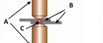
2.1. The automatic welding machine is designed for welding the pipe and flange of the valve (circular seam) with electrode wire in a protective gas environment. The machine provides supply of the workpiece to the welding zone, turning welding on and off, rotation of the workpiece, and removal of the welded part to the unloading zone.
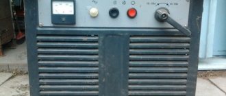
2.2 The welding machine consists of: a rotary table equipped with an electric drive and positions for installing and fixing workpieces; electric drive for rotating the workpiece; mechanism for supplying welding voltage to the body of the part; welding torch mounted on a rod; mechanism for feeding electrode wire and shielding gas into the welding zone PDG-350; welding rectifier with rigid external characteristic VS-632; control unit BUSP-A1.
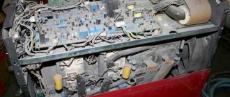
3.1. The control unit is structurally designed as a separate cabinet and has a control panel (Fig. 1), a fuse panel, and connectors for connecting external circuits. The necessary supply voltages are provided by a transformer located in the welding rectifier VS-632. in the control unit cabinet (Fig. 2) there are diode rectifiers, switching relays, and drive speed control boards. The purpose of the controls and indications located on the control panel is shown in Fig. 1.
3.2. To control the welding process in automatic mode, a programmable microcontroller with non-volatile memory is used. The microcontroller (PC) board is located on the control panel and provides installation and indication of the welding cycle parameters, setting the rotation speed of the drives, indicating the number of completed cycles, and audible signaling of the start of the cycle.
After the “START” command (button 15 Fig. 1), the welding cycle begins with turning the table in the direction selected by toggle switch 25 Fig. 1. The table stops when the position with the workpiece enters the welding zone and the SB5 sensor is triggered (Fig. 4). after the end of the time delay (parameter 1 of Table 1), the rotation of the workpiece, the mechanism for supplying the welding wire and shielding gas, and the mechanism for supplying welding voltage are turned on. The direction of rotation of the workpiece is set by toggle switch 26 in Fig. 1. The angle of rotation of the workpiece in the welding zone is determined by parameter 2, table. 1 value of which is the number of pulses issued by the DKP-11 sensor (Fig. 4) when the teeth of the rotary gear pass. The end of the countdown of the set number of pulses is a command to stop welding and rotate the part. If during the welding process the “STOP” command was given (button 16, Fig. 1), the countdown stops and will continue after pressing button 15 — “START”. To switch to the beginning of pulse counting, you must briefly move toggle switch 2 (Fig. 1) to the “MANUAL” position.
After the end of welding and a pause (parameter 3 of Table 1), the table rotation is turned on, the part is removed from the welding zone, and the next workpiece takes its place and the process is repeated.
In manual control mode, the activation and deactivation of actuators is performed by the operator.
4.1. When operating an automatic welding machine, the parameters for setting the rotation speed of the drives and the angle of rotation of the part in the welding zone are of decisive importance. The drive rotation speed should be set in the mode of indicating the count of completed cycles or the angle of rotation (selected by button 3 in Fig. 1). Set the values using the +/- buttons (positions 6, 8 Fig. 1), the setting values in conventional units are displayed on indicators 7 and 9. If you use button 3 to enter the “installation”
, then using buttons 8 you can select the parameter number, and using buttons 9 you can change its value. So, to set the angle of rotation of the workpiece in the welding zone, you need to select parameter No. 2 on indicator 7 (Table 1) and set on indicator 8 the number of gear teeth by which it will rotate when working out one welding cycle.
When operating in both automatic and manual modes, the main ones are the “START” and “STOP” buttons, installed on the control panel and duplicated on the remote control. To set up and check the mechanisms of the automatic welding machine, the welding mode can be turned off using toggle switch 22 Fig. 1. When adjusting the position of the electromagnet of the welding voltage supply mechanism, it is necessary to use the welding voltage switch located on the rectifier (see the BC-632 operating manual).
The provisions related to the operation and maintenance of the welding torch, wire feed mechanism and shielding gas are set out in the technical data sheet of the PDG-350 unit and correspond to semi-automatic welding modes. Mandatory are the SAFETY MEASURES specified in the passport of the PDG-350 unit and compliance with the “RULES FOR OPERATING ELECTRICAL INSTALLATIONS AND SAFETY RULES FOR OPERATING ELECTRICAL INSTALLATIONS OF CONSUMERS” (PTZ and PTB) and “REQUIREMENTS OF THE STANDARDS OF THE SAFETY SYSTEM YES" (SSBT).
Homemade welding machines, semi-automatic machines, circuits
I propose a new scheme for a semi-automatic welding machine. This is a modification of the diagram published here.
A distinctive feature of this circuit is the use of one voltage source of 12 volts and CMOS series microcircuits, namely K561TL1, are used as logic elements in the control unit.
This scheme uses 2 welding modes: manual and automatic .
The circuit has the ability to disable pre-gas and post-gas delays if you don’t need them; we’ll call this operating mode without delays . You can also turn off the delays if you are welding with cored wire (pre-gas and post-gas delays are useless here).
Actually the scheme itself:
If you have problems opening the diagram image, you can view it at this link:
Possible version of a double-sided printed circuit board, dimensions 100x110 mm:
The PCB file for the DipTrace can be downloaded from this link:
Printed circuit board Svapka.Ru Vol 2.0769
There is no power supply for the control board on the printed circuit board. Everyone makes from what they have, so I didn’t place it on the board.
Another version of the printed circuit board for this circuit. The fee is one-sided. Resistors, capacitors and diodes SMD, size 73x76 (after final trimming), 8 jumpers:
Of course, the food paths need to be made wider. SMD resistors and capacitors size 1206, diodes LL4148.
The PCB file for the DipTrace can be downloaded from this link..
Printed circuit board Svapka.Ru Vol 2.0 SMD672
Photos of the finished board in SMD version. The board works great.
This was my first time working with a solder mask, so the results were not very good. Well, I don't think it matters. I did not solder in the trimming resistors; instead I installed 1 mOhm resistors. At these ratings, the delay time is 1 second.
Of course, the board needs to be finalized in terms of the arrangement of the elements so that nothing interferes with it. The 12 volt terminal block is located a little poorly, but for this you have a printed circuit board file where you can correct everything.
Also.. if someone can figure it out better from my files, then share the seals (please). 
Relays K1 and K2 of type HJR-3FF or HJR-21FF
Let me briefly describe the principle of operation of the circuit.
The operating algorithm is as follows:
- When you press the control button, carbon dioxide is supplied first, this is done so that the burner is filled with gas.
- After a delay of 1..3 seconds, the welding current and wire feed are automatically turned on.
- After releasing the control button, the wire feed is switched off.
- Then, after 1..3 seconds, the supply of carbon dioxide is turned off, this is necessary so that the melted metal does not oxidize when cooling, and the welding current is turned off.
Manual mode.
The circuit is in its original state, control button SB1 is released. Switch SA1 ( Auto/manual ) is in the upper position according to the diagram. Switch SA2 ( No delays ) is in the lower position according to the diagram, that is, the pre-throttle and post-throttle delays are turned on.
When the control button is pressed, logical 1 opens the gas valve through diode VD4. Also starts the delay circuit assembled on D1.1 and D1.2. After the time specified by the chain R6, C4, a logical 1 appears at output 4 of element D1.2, which triggers the motor relay through the diode VD9. At the same time, log 1 appears at output 11 D1.4, which turns on the current relay through the VD6 diode.
At this time, the welding process is underway.
When the control button is pressed, a logical 0 appears at output 4 of element D1.2, which turns off the motor relay. Then, after a time specified by the chain R9, C9, log 0 appears at output 11 of D1.4, which turns off the current relay and gas valve.
At this time the welding is completed.
Auto mode.
The circuit is in its original state, control button SB1 is released. Switch SA1 ( Auto/manual ) is in the lower position according to the diagram. Switch SA2 ( No delays ) is in the lower position according to the diagram, that is, the pre-throttle and post-throttle delays are turned on.
The circuit in this mode works according to the same algorithm as in manual mode, only the welding time is set by the chain C2, R5. With these ratings, the welding time is adjustable within 0..15 sec.
I would like to note that the button must be held in this mode. At the end of the time, the circuit itself will stop the welding process.
If you change your mind about welding in automatic mode, just release the control button and welding will stop.
Under No delay mode.
The circuit is in its original state, control button SB1 is released. Switch SA1 ( Auto/manual ) is in the upper position according to the diagram. Switch SA2 ( No delays ) is in the upper position according to the diagram, that is, the pre-throttle and post-throttle delays are turned off.
When the control button is pressed, logical 1 through diodes VD4, VD10, VD11 opens the gas valve of the motor relay and the current relay simultaneously, that is, there are no delays. When you release the control button, everything also turns off at the same time.
Same thing in automatic mode.
The mode without delays is needed for the case when we weld with cored wire, when these delays are not needed. Or for some other reason, for example, if there is little gas left (to save money) or you need to quickly grab something, where the quality of the seam is not so important.
Setup.
The device assembled according to this scheme should work immediately without any problems.
The adjustment of the pre-gas and post-gas delay times is regulated by resistors R6 and R9. With these ratings R6, C4 and R9, C9, the maximum delay time is approximately 1 second. If you need more, you can install capacitors C4 and C9 of larger capacity, for example 3 μF.
These capacitors are not polarized. But no one forbids using electrolytic ones instead without changing the circuit.
In automatic mode, you need to select resistor R4 so that there is no empty movement (useless) of resistor R2.
Push.
If someone doesn’t need automatic mode, then we simply don’t assemble this unit.
I do not recommend replacing the K561TL1 microcircuit with something else; there may be problems with switching logic elements.
I am adding another scheme Svapka.Ru Vol 2.1
If you have problems opening the diagram image, you can view it at this link:
There is no printed circuit board for this circuit yet.
The delay node operation algorithm is slightly different.
Press the control button:
- The gas valve and current are turned on.
- Delay.. the motor turns on.
Release the control button:
- The motor turns off.
- Delay.. the current and gas are turned off.
I am adding another version of Svapka.Ru Vol 2.2 (Victor)
Victor assembled this circuit and shared the printed circuit board, which can be downloaded here..
Printed circuit board Svapka.Ru Vol 2.2 (Victor)715
Photo of the assembled printed circuit board.
Work algorithm:
- When you press the control button, the gas and current are immediately turned on simultaneously.
- After a delay of 1..3 seconds, the wire feed is automatically turned on.
- After releasing the control button, the wire feed is immediately switched off.
- Then, after 1...3 seconds, the supply of carbon dioxide and welding current are turned off simultaneously.
Look like that's it!
Have fun and happy stitching!
Author of the article: Admin
Did you like the article? If it's not difficult, please vote:
Share this article
Related Posts
Scheme of a homemade semi-automatic welding machine.
Scheme of a simple homemade semi-automatic welding machine
Scheme of a semi-automatic welding machine with a welding current regulator on the primary winding.
Rice. 1
1. «Net
» — toggle switch on/off.
power supply for welding machine; " Auto/manual"
— toggle switch on/off.
automatic welding mode and reset the welding timer (in the manual position)
;
" Ustan.
» — button for selecting display modes: counting welding cycles;
angle of rotation of the part in the welding zone; turning on the “ installation
” mode;
“ Reset
” - button to reset the counter of completed welding cycles;
“ Time/quantity
” - digital indicator displaying: the angle of rotation of the part in the welding zone;
number of welding cycles performed; turning on the “ installation
” mode;
“ M2-/M2+”
- buttons for setting the rotation speed of the part in the welding zone and selecting the parameter number to set;
“ M2
” - digital indicator of the set rotation speed of the part in the welding zone;
timer numbers in the “ installation
” mode;
“ M1-/M1+
” - buttons for setting the speed of rotation of the slipway;
timers; “ M1
” - digital indicator of the set table rotation speed;
time of the selected timer; “ Automatic
” - indicator for turning on the automatic welding mode;
“ Reverse M2
” - indicator of the direction of rotation of the part;
« Gr.
» — Sound signal volume control;
“ Reverse M1
” - indicator of the direction of rotation of the table;
“ Start
”—indicator for starting the welding machine;
“ Start
” - button to start the welding machine;
“ Stop
” – button to stop the welding machine;
“ M1
” — indicator for turning on the table rotation;
“ M2
” - indicator for turning on the rotation of the part;
“ Dat.
Svar. current "—indicator of the presence of welding current;
“ Dat.
Svar. current » - toggle switch for blocking the disconnection of the welding current sensor;
“ Welding
”—indicator that the welding source is turned on;
“ Welding
” - toggle switch to turn on/off the welding source;
“ Dat.
Conc. » — indicator of operation of the table position limit sensor;
“Dat.
Conc. » — button duplicating the table position limit sensor; Toggle switch for selecting the direction of rotation of the table; Toggle switch for selecting the direction of rotation of the part.
Table 1
Table of parameters in the “INSTALLATION” mode
| N parameter (indicator 7, selection – buttons 6) |