Electric arc welding of parts includes two main components. The first is the metal products being connected, the second is the additional metal that connects them. At the same time, it is important to determine the optimal consumption of electrodes per 1 m of seam using a calculator for calculation, which today can be found on the Internet.
The reason here is not only financial, but also technological. The weight of the connecting metal makes the finished product heavier, and this value can reach up to 1.5% of its initial weight.
If this is not important for static elements, then for moving mechanisms it can be significant, even critical.
Theory and practice of calculation
The difference in theory and practice largely depends on the conditions in which the welding will be performed, as well as on the skill of the welder, which is determined by the discharge. Read about what the categories of welders are and what they are in our article at the link.
If the process takes place in the wind or in uncomfortable conditions (in cramped spaces where there is no normal access), the welder will burn more electrodes. Therefore, the welding conditions must be taken into account when calculating.
If you are guided by VSN, then you can use the calculation method based on the loss coefficient. Its formula is as follows:
G=m * K.
K is the loss coefficient used for various brands, which we listed above in the table (range 1.5 -1.9).
M is the mass of the deposited metal. This value is calculated by multiplying the cross-sectional area of the deposited metal by its density (m = p*F).
As a result, we obtain the following formula for calculating losses per 1 m of seam:
H= P * F * K.
If you need to determine losses for a specific length, in this case the formula looks like:
H= P * F * K * L.
where L is the length value. In some sources, the formula has a different form:
H=G*L
where G= K * m - it is called the specific consumption rate;
L is still the same value of the seam length.
Calculation of losses in practice is determined not by formulas, but experimentally.
To do this, the electrodes are first weighed. Next, two welders weld joints of the same type (the same thickness, diameter and edge preparation) that will be performed during the work.
As a result, control weighing of the remaining welding materials is carried out and the results obtained are compared with the values of the theoretical calculation. This is where the practical consumption coefficient comes from.
Consumption pr./Exp. theory = Coef. consumables etc.
Next, when ordering materials, the values obtained from theoretical calculations are multiplied by the practical consumption coefficient.
Example: if during the calculation we received a value of 10 kg, and the consumption coefficient. etc. is 1.42, then to obtain practical consumption:
10 kg*1.42 = 14.2 kg. Thus we get real losses.
Way to reduce costs
To improve economic performance, it is necessary to strictly implement technological rules. The qualifications of the welder are essential. To eliminate errors and inaccuracies caused by human factors, specialized automatic machines are used. Investments in the purchase of more complex equipment pay off during operation by reducing consumables consumed by 10-15%.
To reduce costs, you need to strictly follow technological rules.
Electrodes should be used only in the modes recommended by the manufacturer.
Deviations from the design current increase the consumption of materials or deteriorate the quality of the weld.
If manual technology is used, the final result largely depends on the skills of the welder. For this reason, some experts prefer a practical calculation method. By creating several control seams, you can accurately determine the material consumption under working conditions.
We recommend reading Technical characteristics of MP-3 electrodes
Error
Even the use of data obtained practically does not guarantee that losses will not increase. Often, when performing work on site, there may be wind, power surges, and materials may not be completely dried and many other factors that will affect overruns.
Also, during operation, defective electrodes may be identified: rusty, with chipped or swollen coating. They will not be able to be used.
Khafizov Ildar
Level IV NAKS specialist
Ask a Question
Based on practical experience, when ordering electrodes, I recommend adding an additional 3 to 5% to ensure process continuity. Because delivery of materials in case of shortage requires much higher costs.
To avoid problems with a large number of defective materials when purchasing, you need to open one pack from the batch and weld test samples. This can determine the quality of the electrodes and their suitability.
This can significantly save the budget if a large amount of materials is purchased (more than 1 ton).
We calculate the consumption of welding filler material in pieces
For small-scale welding operations, piece-by-piece calculation of the filler material is necessary. For example, you may need 50 welding electrodes of the UONI-13/45 brand with a diameter of 3 millimeters, of which there are 40 pieces in one kilogram. Then buying one and a half kilos will give a considerable surplus, and weighing with an accuracy of a gram will be too difficult.
By the way, it is the diameter that we need to calculate the number of filler materials in pieces, since the mass of metal deposited by one electrode in grams, which will be needed for the formula, depends on this value. We find the quantity for welding in one pass: HOP = 103ML/ME, where ME is the same melt mass of one rod in grams, which can be taken from the following table.
| Electrode brand | Electrode diameter of standard length, mm | |||
| 3,0 | 4,0 | 5,0 | 6,0 | |
| ANO-1 | — | 71,1 | 111,7 | 160,9 |
| ANO-4 | 15,4 | 35,2 | 55,3 | 79,6 |
| ANO-5 | 19,0 | 43,5 | 68,3 | — |
| ANO-b, ANO-6U | 15,4 | 35,2 | 54,9 | 78,9 |
| MR-3 | 14,7 | 33,7 | 54,1 | 77,4 |
| OZS-4 | 14,9 | 34,5 | 54,6 | 78,6 |
| OZS-6 | 19,0 | 43,5 | 68,4 | 98,5 |
| OZS-12 | 15,3 | 35,1 | 55,3 | 79,6 |
| ANO-12 | 12,1 | 27,7 | 43,5 | 62,5 |
| ANO-13 | 14,6 | 36,5 | 48,4 | — |
| ANO-29M | 15,8 | 35,7 | 55,2 | — |
| ANO-27 | 19,0 | 43,5 | 68,3 | — |
| DSK-50 | — | 41,2 | 64,7 | — |
| TMU-21U | 16,6 | 38,1 | 59,8 | — |
| TML-1U | 15,9 | 36,4 | 57,1 | — |
| ANO-TM | 16,6 | 38,1 | 59,8 | — |
| ANO-TM60 | 16,6 | 38,1 | 59,8 | — |
| ANO-10 | — | 66,7 | 104,8 | 151,1 |
| ANO-11 | 19,0 | 43,5 | 68,3 | — |
| SM-11 | — | 44,3 | 69,6 | 100,3 |
| UONI-13/45 | 16,6 | 38,1 | 59,8 | 86,2 |
| UONI-13/55 | 15,6 | 35,7 | 56,1 | 80,8 |
| UONI-13/55U | 16,6 | 38,1 | 59,8 | 86,2 |
| UONI-13/65 | 15,9 | 36,4 | 57,1 | — |
| UONI-13/85 | 17,9 | 41,1 | 64,5 | — |
| UONI-13/85U | 16,8 | 38,5 | 60,4 | — |
| OZL-8 | 14,5 | 33,2 | 52,2 | — |
| OZL-6 | 14,8 | 35,3 | 56,5 | — |
| TsL-11 | 15,6 | 35,8 | 56,3 | — |
| EA-395/9 | 14,5 | 33,2 | 52,2 | — |
| EA-981/15 | 16,3 | 37,3 | 58,5 | 84,3 |
| TsT-28 | 15,6 | 35,8 | 56,3 | 81,1 |
| TsT-15 | 14,5 | 33,2 | 52,2 | — |
| ANZHR-1 | 16,3 | 37,3 | 58,5 | 84,3 |
| ANZHR-2 | 15,6 | 35,8 | 56,3 | 81,1 |
However, often the seam has to be welded in several passes, which means that the number of consumed electrodes will increase significantly. For such compounds we use a slightly different formula, which looks like HMP = (10
3
M - m )L/ME , where m is the mass of metal from the melting of one rod during the formation of the root weld. The latter indicator is determined separately by the given welding speed and current strength: m = ( aHI )/ U , where aH is the deposition coefficient from the characteristics of the electrode, I is the current strength (A), and U is the welding speed (m/h).
This is interesting: Direct and reverse polarity when welding
Consumption of electrodes per 1 ton of metal structures
Electrode losses can be calculated based on the mass of metal structures being welded - per ton of metal. This is a fairly rough estimate. It can be used in cases where a large amount of work remains. The result obtained is the upper limit for the consumption of welding materials.
The formula is as follows:
H= 0.011* Mcr.;
H - Required number of electrodes
Microdistrict — Mass of metal structures to be welded.
How to determine the cost of electrodes in kilograms?
In welding work, there is such a thing as filler material consumption rates, which are necessary, although difficult, to adhere to due to the specific nature of metal melting, which depends on many factors. In general, the definition of this standard is as follows: H = M + MO, where M corresponds to the mass of welded metal, and MO is the mass of waste, which accounts for the combustion of the rod, its spattering, and cinders.
However, this formula is too approximate; it does not take into account many factors that affect the costs of electrodes. Therefore, let's consider a more detailed calculation. When parts and structures are to be welded on a large scale, the filler material is purchased not in pieces, but in kilograms, taking into account the reduction in the weight of the electrodes during the drying process. In this case, it is advisable to calculate the consumption of welding electrodes per 1 meter of weld during welding to calculate their mass.
In this case, we will need such values as the weight of the deposited metal and its cross-sectional area for a given sheet thickness. The general calculation of the cost of electrodes per 1 kg of melt looks like H = MKP, where KP is the loss coefficient of a filler material of a certain brand, taking into account the combustion of the rod, splashes and remaining cinders. This coefficient is taken from the following table:
| Electrode cost factor | Group of stamps | Brand of coated electrode for welding steels | |
| Carbon and low alloy | Heat resistant and highly alloyed | ||
| 1,5 | I | ANO-1, ANG-1K, OZS-17N, ANO-19M, DSK-50, ANP-6P, NIAT-3M | TML-1U, TML-3U, OZL-25, TsT-28, ANV-17, ANZHR-1, ANZHR-2 |
| 1,6 | II | OZS-23, VN-48, UP-1/45, ANO-5, ANO-13, ANO-19, ANO-20, OZS-6, ANO-10, ANO-11, ANO-30, ANO-TM, VSO-50SK, OZS-18, OZS-25, UONI-13/55U, ANO-TM60, VSF-65, ANO-TM70, ANP-2, UONI-13/65, UONI-13/85 | TsL-20, KTI-7A, OZL-6, ZiO-8, OZL-8, ANV-13, ANV-34, NIAT-4, NIAT-5, NII-48G |
| 1,7 | III | ANO-4, ANO-6, ANO-6U, ANO-21, ANO-24, ANO-29M, ANO-32, MR-3, OZS-4, OZS-12, OZS-21, SM-11, UONI- 13/45, UONI-13/45, UONI-13/45SM, ANO-27, ANO-25, UONI-13/55,UONI-13/55SM, ITS-4S, OZS-24 | TsU-5, TMU-21U, TsL-51, UONI-13/NZH, OZL-9A, TsT-15, OZL-17U, TsL-11 |
| 1,8 | IV | WCC-4, K-5A | NZh-13, EA-395/9, EA-981/15 |
For all types of welded joints, GOSTs 5264-80 and 11534-75 specify symbols of the form C1, C2, and so on. The mass of a melt 1 meter long is determined by the formula M = FpL10-3 for compounds of types C1, C3, C26, U1, U2, U4, U5, T1, T3, H1 and H2. In this calculation, F is the cross-sectional area of the weld, p is the density of carbon and low-alloy steels (7.85 g/cm3), and L is the specified length of the melt.
For other types of connections, the formula takes a different form: M = (0.8F + 0.5S)pL10-3, where S is the thickness of the metal sheet. In this case, the cross-sectional area of the seam in both formulas is calculated for each type of connection in a certain way, according to the values taken from GOST 5264-80. For C5 this will look like F = Sb + 0.75eg, where b is the distance between the plates, and e and g are the width and height of the seam, respectively.
Sometimes, when calculating the cross-sectional area of a weld, it is necessary to take into account the angle of the beveled edge of the workpiece, determining its tangent to be included in the formula.
Calculation of the number of electrodes per 1 meter of seam
To determine material costs per 1 m2, it is best to use the tables that you can find in our article below. The tables already indicate the amount of consumption only for the welding operation. When calculating the total quantity, it is necessary to take into account the loss of materials for making tacks.
To do this you need to use the following formula:
N = Nsv + Np.
where H is the required amount of electrode metal that will be required for welding 1 m long.
NSV - consumption for a welding operation - value from the table;
Np - Cost of tack welding.
The value of Np is calculated using the formula:
Нп = 0.15*Нсв
For thickness of welded parts less than 12 mm.
If the thickness is more than 12 mm, then the formula looks like:
Нп = 0.12*Нсв
For the convenience of calculating the consumption of electrodes per 1 m of seam, use calculators made by our specialists. You can download them to your computer or open them online.
For calculations when welding pipes
Calculator
For calculations when welding sheets and profile structures
Calculator
Useful article - Which electrodes to cook stainless steel with?
Tables
Consumption rates for welding materials are determined using a coefficient. This parameter is taken from special tables. If you need to determine the consumption of electrodes, for example, in pipe welding, then you should use the table.
To simplify calculations, you can use ready-made tables that provide ready-made data. It is much easier to use such material in production than to perform new calculations each time.
Standards for manual arc welding with coated rods are given in the tables below.
The norm is for 1 joint.
| Pipe size, mm | Weight of deposited metal, g | Electrodes by groups, g | Line code | ||||
| II | III | IV | V | VI | |||
| 45´3 | 21 | 37 | 40 | 42 | 44 | 47 | 1 |
| 45´4 | 28 | 50 | 54 | 57 | 61 | 64 | 2 |
| 57´3 | 27 | 57 | 60 | 54 | 67 | 60 | 3 |
| 57´4 | 36 | 64 | 69 | 73 | 77 | 82 | 4 |
| 76´5 | 61 | 108 | 108 | 123 | 130 | 137 | 5 |
The norm for 1 m of seam.
| Thickness walls, mm | Weight of deposited metal, g | El-dy by groups, gr | Line code | ||||
| II | III | IV | V | VI | |||
| 3 | 152 | 269 | 286 | 305 | 322 | 340 | 1 |
| 4 | 207 | 368 | 393 | 417 | 442 | 466 | 2 |
| 5 | 262 | 465 | 497 | 527 | 558 | 590 | 3 |
Costs for forming vertical pipeline joints with beveled edges
1 m seam.
| Wall thickness, mm | Weight of deposited metal, g | El-dy by groups, gr | Line code | ||||
| II | III | IV | V | VI | |||
| 3 | 201 | 366 | 390 | 415 | 439 | 464 | 1 |
| 4 | 249 | 453 | 484 | 514 | 544 | 574 | 2 |
| 5 | 330 | 600 | 640 | 680 | 820 | 760 | 3 |
| 6 | 474 | 861 | 918 | 975 | 1033 | 1090 | 4 |
| 8 | 651 | 1182 | 1261 | 1410 | 1419 | 1498 | 5 |
| 10 | 885 | 1607 | 1714 | 1821 | 1928 | 2035 | 6 |
| 12 | 1166 | 2116 | 2257 | 2398 | 2539 | 2680 | 7 |
| 15 | 1893 | 3436 | 3665 | 3894 | 4123 | 4352 | 8 |
| 16 | 2081 | 3778 | 4030 | 4281 | 4533 | 4785 | 9 |
| 18 | 2297 | 4532 | 4834 | 5136 | 5438 | 5740 | 10 |
1 joint.
| Pipe size, mm | Weight metal, g | El-dy, Mr. | Line code | ||||
| II | III | IV | V | VI | |||
| 45´3 | 27 | 60 | 54 | 58 | 61 | 64 | 1 |
| 45´4 | 34 | 62 | 66 | 70 | 74 | 79 | 2 |
| 57´3 | 35 | 64 | 69 | 73 | 77 | 82 | 3 |
| 57´4 | 44 | 79 | 85 | 90 | 95 | 100 | 4 |
| 76´5 | 77 | 140 | 149 | 158 | 168 | 177 | 5 |
| 89´6 | 130 | 235 | 251 | 266 | 282 | 298 | 6 |
| 108´6 | 158 | 287 | 306 | 325 | 344 | 363 | 7 |
| 133´6 | 195 | 354 | 377 | 401 | 425 | 448 | 8 |
| 133´8 | 268 | 483 | 516 | 548 | 580 | 613 | 9 |
| 159´6 | 234 | 424 | 453 | 481 | 509 | 537 | 10 |
| 159´8 | 320 | 580 | 619 | 658 | 697 | 735 | 11 |
| 219´6 | 323 | 586 | 625 | 664 | 703 | 742 | 12 |
| 219´8 | 442 | 803 | 856 | 910 | 963 | 1017 | 13 |
| 219´10 | 599 | 1088 | 1160 | 1233 | 1305 | 1376 | 14 |
| 219´12 | 787 | 1428 | 1523 | 1619 | 1714 | 1809 | 15 |
| 273´8 | 553 | 1003 | 1071 | 1138 | 1205 | 1272 | 16 |
| 273´10 | 750 | 1361 | 1452 | 1542 | 1633 | 1724 | 17 |
| 273´12 | 985 | 1788 | 1907 | 2026 | 2145 | 2265 | 18 |
| 273´15 | 1592 | 2890 | 3082 | 3275 | 3467 | 3660 | 19 |
| 325´8 | 659 | 1196 | 1276 | 1357 | 1436 | 1516 | 20 |
| 325´10 | 894 | 1623 | 1731 | 1839 | 1947 | 2055 | 21 |
| 325´12 | 1175 | 2133 | 2275 | 2417 | 2559 | 2701 | 22 |
| 325´15 | 1902 | 3453 | 3683 | 3913 | 4144 | 4374 | 23 |
| 377´8 | 765 | 1389 | 1482 | 1576 | 1667 | 1760 | 24 |
| 377´10 | 1039 | 1885 | 2010 | 2136 | 2261 | 2387 | 25 |
| 377´12 | 1365 | 2478 | 2643 | 2808 | 2973 | 3138 | 26 |
| 377´15 | 2211 | 4013 | 4281 | 4548 | 4816 | 5083 | 27 |
| 426´10 | 1175 | 2132 | 2274 | 2416 | 2558 | 2700 | 28 |
| 426´12 | 1545 | 2804 | 2990 | 3177 | 3364 | 3551 | 29 |
| 426´16 | 2759 | 4991 | 5324 | 5655 | 5988 | 6321 | 30 |
| 465´18 | 3598 | 6531 | 6966 | 7401 | 7836 | 8271 | 31 |
Horizontal pipeline connections with one edge beveled
1 m seam.
| Wall thickness, mm | Weight metal, gr | Electrodes, g | Line code | ||||
| II | III | IV | V | VI | |||
| 3 | 232 | 411 | 438 | 466 | 493 | 521 | 1 |
| 4 | 299 | 529 | 564 | 599 | 635 | 670 | 2 |
| 5 | 384 | 680 | 724 | 770 | 816 | 861 | 3 |
| 6 | 470 | 832 | 887 | 943 | 998 | 1054 | 4 |
| 8 | 832 | 1474 | 1573 | 1671 | 1769 | 1868 | 5 |
| 10 | 1110 | 1965 | 2096 | 2227 | 2358 | 2489 | 6 |
| 12 | 1562 | 2765 | 2949 | 3133 | 3318 | 3502 | 7 |
| 15 | 2137 | 3782 | 4034 | 4287 | 4539 | 4791 | 8 |
| 16 | 2348 | 4157 | 4434 | 4712 | 4989 | 5266 | 9 |
| 18 | 2786 | 4931 | 5260 | 5588 | 5917 | 6246 | 10 |
1 joint.
| Pipe size, mm | Weight metal, gr | El-dy, gr | Line code | ||||
| II | III | IV | V | VI | |||
| 57´3 | 41 | 72 | 77 | 82 | 87 | 92 | 1 |
| 57´4 | 53 | 93 | 99 | 105 | 111 | 117 | 2 |
| 76´5 | 89 | 158 | 169 | 179 | 190 | 201 | 3 |
| 89´6 | 128 | 227 | 242 | 257 | 272 | 288 | 4 |
| 108´6 | 157 | 277 | 295 | 314 | 332 | 351 | 5 |
| 133´6 | 193 | 342 | 365 | 388 | 410 | 433 | 6 |
| 133´8 | 341 | 603 | 643 | 683 | 723 | 764 | 7 |
| 159´6 | 232 | 410 | 437 | 465 | 492 | 520 | 8 |
| 159´8 | 482 | 724 | 772 | 820 | 869 | 917 | 9 |
| 219´6 | 320 | 567 | 604 | 642 | 680 | 718 | 10 |
| 219´8 | 565 | 1001 | 1068 | 1135 | 1201 | 1268 | 11 |
| 219´10 | 751 | 1330 | 1419 | 1508 | 1596 | 1685 | 12 |
| 219´12 | 1054 | 1866 | 1991 | 2115 | 2240 | 2364 | 13 |
| 273´8 | 1707 | 1251 | 1335 | 1419 | 1502 | 1586 | 14 |
| 273´10 | 940 | 1664 | 1775 | 1886 | 1997 | 2108 | 15 |
| 273´12 | 1320 | 2336 | 2492 | 2647 | 2804 | 2959 | 16 |
| 273´15 | 1797 | 3181 | 3393 | 3605 | 3817 | 4029 | 17 |
| 325´8 | 843 | 1492 | 1592 | 1691 | 1790 | 1890 | 18 |
| 325´10 | 1121 | 1985 | 2117 | 2249 | 2382 | 2514 | 19 |
| 325´12 | 1575 | 2787 | 2973 | 3158 | 3344 | 3530 | 20 |
| 325´15 | 2147 | 3801 | 4064 | 4308 | 4562 | 4815 | 21 |
| 377´10 | 1302 | 2035 | 2459 | 2612 | 2766 | 2920 | 22 |
| 377´12 | 1829 | 3238 | 3530 | 3669 | 3885 | 4101 | 23 |
| 377´16 | 2741 | 4851 | 5174 | 5449 | 5822 | 6145 | 24 |
| 465´18 | 4015 | 7106 | 7580 | 8052 | 8526 | 9000 | 25 |
C19 vertical joints with beveled edges
1 m seam.
| Thickness Art., mm | Weight metal, gr | El-dy, gr | Line code | ||||
| II | III | IV | V | VI | |||
| 3 | 201 | 366 | 390 | 415 | 439 | 464 | 1 |
| 4 | 260 | 472 | 503 | 535 | 566 | 598 | 2 |
| 5 | 329 | 599 | 639 | 679 | 719 | 759 | 3 |
| 6 | 464 | 842 | 898 | 955 | 1011 | 1067 | 4 |
| 8 | 670 | 1216 | 1297 | 1378 | 1459 | 1540 | 5 |
| 10 | 974 | 1768 | 1885 | 2004 | 2121 | 2240 | 6 |
| 12 | 1250 | 2269 | 2420 | 2571 | 2722 | 2874 | 7 |
| 15 | 2010 | 3649 | 3894 | 4137 | 4380 | 4623 | 8 |
| 16 | 2204 | 4000 | 4266 | 4534 | 4800 | 5067 | 9 |
| 18 | 2615 | 4748 | 5063 | 5378 | 5695 | 6011 | 10 |
1 joint.
| Pipe size, mm | Weight metal, gr | El-dy, gr | Line code | ||||
| II | III | IV | V | VI | |||
| 45´3 | 27 | 50 | 54 | 58 | 61 | 64 | 1 |
| 45´4 | 36 | 65 | 69 | 73 | 77 | 82 | 2 |
| 57´3 | 35 | 64 | 69 | 73 | 77 | 82 | 3 |
| 57´4 | 46 | 83 | 88 | 94 | 99 | 105 | 4 |
| 76´5 | 77 | 140 | 149 | 158 | 167 | 177 | 5 |
| 89´6 | 127 | 230 | 245 | 261 | 276 | 291 | 6 |
| 108´6 | 154 | 280 | 299 | 318 | 337 | 355 | 7 |
| 133´6 | 191 | 346 | 369 | 392 | 415 | 438 | 8 |
| 133´8 | 274 | 497 | 530 | 564 | 597 | 630 | 9 |
| 159´6 | 229 | 415 | 443 | 471 | 498 | 526 | 10 |
| 159´8 | 329 | 597 | 637 | 677 | 716 | 756 | 11 |
| 219´6 | 216 | 573 | 611 | 650 | 683 | 727 | 12 |
| 219´8 | 455 | 826 | 881 | 936 | 991 | 1046 | 13 |
| 219´10 | 659 | 1197 | 1276 | 1357 | 1436 | 1516 | 14 |
| 219´12 | 844 | 1532 | 1633 | 1735 | 1837 | 1940 | 15 |
| 273´8 | 569 | 1032 | 1101 | 1170 | 1239 | 1307 | 16 |
| 273´10 | 825 | 1497 | 1597 | 1697 | 1796 | 1897 | 17 |
| 273´12 | 1056 | 1917 | 2045 | 2172 | 2300 | 2428 | 18 |
| 273´15 | 1691 | 3069 | 3275 | 3479 | 3684 | 3880 | 19 |
| 325´8 | 678 | 1231 | 1313 | 1394 | 1476 | 1580 | 20 |
| 325´10 | 984 | 1786 | 1904 | 2024 | 2142 | 2262 | 21 |
| 325´12 | 1260 | 2287 | 2449 | 2592 | 2744 | 2897 | 22 |
| 325´15 | 2020 | 3667 | 3913 | 4158 | 4402 | 4646 | 23 |
| 377´10 | 1143 | 2074 | 2211 | 2351 | 2488 | 2627 | 24 |
| 377´12 | 1464 | 2657 | 2834 | 3011 | 3187 | 3365 | 25 |
| 377´15 | 2348 | 4262 | 4548 | 4832 | 5116 | 5400 | 26 |
| 426´10 | 1292 | 2346 | 2501 | 2659 | 2815 | 2972 | 27 |
| 426´12 | 1656 | 3006 | 3206 | 3407 | 3607 | 3808 | 28 |
| 426´16 | 2911 | 5284 | 5635 | 5989 | 6341 | 6693 | 29 |
| 465´18 | 3768 | 6839 | 7296 | 7750 | 8206 | 8662 | 30 |
Connections C52 of vertical pipeline joints with curved beveled edges
1 m seam.
| Thickness Art., mm | Weight metal, gr | El-dy, gr | Line code | ||||
| II | III | IV | V | VI | |||
| 10 | 551 | 1371 | 1462 | 1554 | 1645 | 1737 | 1 |
| 12 | 1164 | 2112 | 2253 | 2394 | 2534 | 2675 | 2 |
| 15 | 1606 | 2915 | 3109 | 3303 | 3497 | 3692 | 3 |
| 16 | 1755 | 3185 | 3397 | 3609 | 3821 | 4034 | 4 |
| 18 | 2085 | 3785 | 4037 | 4289 | 4541 | 4794 | 5 |
| 20 | 2409 | 4373 | 4664 | 4956 | 5247 | 5539 | 6 |
| 22 | 2763 | 5015 | 5349 | 5683 | 6017 | 6352 | 7 |
1 joint.
| Pipe dimensions, mm | Weight of filled metal, g | El-dy, gr | Order number | ||||
| II | III | IV | V | VI | |||
| 1 | 2 | 3 | 4 | 5 | 6 | 7 | 8 |
| 133´10 | 310 | 562 | 599 | 637 | 675 | 712 | 1 |
| 159´10 | 370 | 672 | 716 | 762 | 806 | 851 | 2 |
| 159´12 | 570 | 1035 | 1104 | 1173 | 1242 | 1311 | 3 |
| 219´10 | 514 | 932 | 994 | 1057 | 1119 | 1181 | 4 |
| 219´12 | 791 | 1436 | 1532 | 1628 | 1723 | 1819 | 6 |
| 219´16 | 1176 | 2134 | 2276 | 2418 | 2560 | 2703 | 6 |
| 273´10 | 642 | 1165 | 1248 | 1321 | 1398 | 1476 | 7 |
| 273´12 | 989 | 1795 | 1915 | 2035 | 2154 | 2274 | 8 |
| 273´15 | 1349 | 2449 | 2612 | 2775 | 2938 | 3101 | 9 |
| 273´20 | 2024 | 3673 | 3918 | 4163 | 4430 | 4653 | 10 |
| 325´10 | 763 | 1385 | 1477 | 1570 | 1682 | 1754 | 11 |
| 325´12 | 1175 | 2133 | 2276 | 2418 | 2559 | 2702 | 12 |
| 325´15 | 1622 | 2944 | 3140 | 3336 | 3532 | 3729 | 13 |
| 325´18 | 2085 | 3785 | 4037 | 4289 | 4541 | 4794 | 14 |
| 377´10 | 891 | 1618 | 1725 | 1834 | 1941 | 2080 | 15 |
| 377´12 | 1361 | 2471 | 2636 | 2881 | 2965 | 3130 | 16 |
| 377´15 | 1879 | 3411 | 3638 | 3865 | 4092 | 4320 | 17 |
| 377´18 | 2440 | 4429 | 4723 | 5018 | 5313 | 5609 | 18 |
| 426´10 | 1004 | 1823 | 1945 | 2067 | 2188 | 2310 | 19 |
| 426´12 | 1548 | 2809 | 2997 | 3184 | 3370 | 3558 | 20 |
| 426´16 | 2316 | 4204 | 4484 | 4764 | 5044 | 5325 | 21 |
| 426´20 | 3180 | 5772 | 6157 | 6542 | 6962 | 7312 | 22 |
| 465´18 | 3003 | 5450 | 5813 | 6176 | 6539 | 6903 | 23 |
| 465´22 | 3979 | 7222 | 7703 | 8184 | 8665 | 9153 | 24 |
C53 vertical pipeline joints with a curved bevel
1 m seam.
| Thickness Art., mm | Load mass metal, gr | El-dy, gr | Order number | ||||
| II | III | IV | V | VI | |||
| 16 | 1566 | 2843 | 3032 | 3221 | 3411 | 3600 | 1 |
| 18 | 1958 | 3554 | 3790 | 4027 | 4264 | 4501 | 8 |
| 20 | 2314 | 4200 | 4480 | 4760 | 5040 | 5320 | 3 |
| 22 | 2681 | 4866 | 5190 | 5515 | 5839 | 6164 | 4 |
1 joint.
| Pipe size, mm | Weight of metal, g | El-dy by groups, g | Line code | ||||
| II | III | IV | V | VI | |||
| 219´16 | 1053 | 1911 | 2038 | 2165 | 2292 | 2419 | 1 |
| 273´20 | 1940 | 3521 | 3756 | 3991 | 4226 | 4460 | 2 |
| 325´18 | 1958 | 3554 | 3790 | 4027 | 4264 | 4501 | 3 |
| 377´18 | 2281 | 4140 | 4415 | 4691 | 4967 | 5243 | 4 |
| 426´16 | 2070 | 3758 | 4008 | 4258 | 4509 | 4759 | 6 |
| 426´20 | 3052 | 5539 | 5908 | 6278 | 6647 | 7016 | 6 |
| 465´18 | 2822 | 5122 | 5463 | 5804 | 6146 | 6487 | 7 |
| 465´22 | 3855 | 6998 | 7464 | 7931 | 8397 | 8864 | 8 |
Connections U7 corner flanges with pipe
1 m seam.
| Thickness st., m | Load mass metal, gr | El-dy by groups, gr | Lines | ||||
| II | III | IV | V | VI | |||
| 3 | 129 | 234 | 250 | 265 | 281 | 297 | 1 |
| 4 | 186 | 333 | 360 | 383 | 405 | 428 | 2 |
| 5 | 272 | 494 | 527 | 559 | 592 | 625 | 3 |
| 6 | 366 | 664 | 709 | 753 | 797 | 841 | 4 |
| 8 | 494 | 897 | 956 | 1016 | 1076 | 1136 | 6 |
| 10 | 626 | 1136 | 1212 | 1288 | 1363 | 1439 | 6 |
| 12 | 775 | 1407 | 1500 | 1594 | 1688 | 1782 | 7 |
| 15 | 941 | 1708 | 1822 | 1936 | 2049 | 2163 | 8 |
1 flange.
| Pipe dimensions, mm | Weight metal, gr | El-dy by groups, gr | Number | ||||
| II | III | IV | V | VI | |||
| 25´3 | 10 | 18 | 20 | 21 | 22 | 23 | 1 |
| 32´3 | 13 | 23 | 25 | 27 | 28 | 30 | 2 |
| 38´3 | 15 | 28 | 30 | 32 | 33 | 35 | 3 |
| 45´4 | 26 | 48 | 51 | 64 | 57 | 60 | 4 |
| 57´4 | 33 | 60 | 64 | 68 | 72 | 77 | 5 |
| 76´5 | 65 | 118 | 126 | 133 | 141 | 149 | 6 |
| 89´6 | 102 | 186 | 198 | 210 | 223 | 235 | 7 |
| 108´6 | 124 | 225 | 240 | 255 | 270 | 285 | 8 |
| 133´6 | 152 | 277 | 296 | 314 | 333 | 351 | 9 |
| 133´8 | 206 | 375 | 399 | 424 | 449 | 474 | 10 |
| 159´6 | 182 | 331 | 354 | 376 | 398 | 420 | 11 |
| 159´8 | 247 | 448 | 477 | 507 | 537 | 567 | 12 |
| 219´6 | 252 | 457 | 487 | 518 | 548 | 578 | 13 |
| 219´8 | 340 | 617 | 657 | 699 | 740 | 781 | 14 |
| 219´10 | 430 | 781 | 833 | 886 | 937 | 989 | 15 |
| 219´12 | 533 | 967 | 1031 | 1096 | 1161 | 1225 | 16 |
| 273´6 | 313 | 569 | 608 | 645 | 683 | 721 | 17 |
| 273´8 | 424 | 769 | 819 | 871 | 922 | 974 | 18 |
| 273´10 | 536 | 974 | 1039 | 1104 | 1168 | 1233 | 19 |
| 273´12 | 664 | 1206 | 1286 | 1366 | 1447 | 1528 | 20 |
| 325´8 | 504 | 915 | 976 | 1037 | 1098 | 1159 | 21 |
| 325´10 | 639 | 1159 | 1237 | 1314 | 1391 | 1468 | 22 |
| 325´12 | 791 | 1436 | 1531 | 1627 | 1723 | 1818 | 23 |
| 325´15 | 944 | 1743 | 1859 | 1976 | 2091 | 2207 | 24 |
| 377´8 | 585 | 1062 | 1132 | 1203 | 1274 | 1345 | 25 |
| 377´10 | 741 | 1345 | 1435 | 1525 | 1613 | 1703 | 26 |
| 377´12 | 918 | 1666 | 1776 | 1887 | 1998 | 2109 | 27 |
| 377´15 | 1114 | 2022 | 2157 | 2292 | 2426 | 2560 | 28 |
| 426´10 | 837 | 1520 | 1621 | 1723 | 1823 | 1925 | 29 |
| 426´12 | 1037 | 1882 | 2006 | 2132 | 2258 | 2384 | 30 |
| 426´15 | 1260 | 2285 | 2437 | 2590 | 2741 | 2893 | 31 |
Angle U8 flanges with a pipe with a symmetrical bevel of one edge
1 m seam.
| Thickness Art., mm | Weight metal, g | El-dy by groups, g | Order number | ||||
| II | III | IV | V | VI | |||
| 3 | 90 | 163 | 174 | 185 | 196 | 207 | 1 |
| 4 | 165 | 299 | 319 | 339 | 359 | 379 | 2 |
| 5 | 285 | 517 | 552 | 586 | 621 | 655 | 3 |
| 6 | 411 | 746 | 796 | 845 | 895 | 945 | 4 |
| 8 | 592 | 1076 | 1148 | 1220 | 1292 | 1363 | 5 |
| 10 | 770 | 1398 | 1491 | 1584 | 1677 | 1770 | 6 |
| 12 | 970 | 1761 | 1878 | 1995 | 2113 | 2230 | 7 |
| 15 | 1192 | 2163 | 2308 | 2452 | 2596 | 2740 | 8 |
Angular U8 flanges.
1 m seam.
| Thickness Art., mm | Weight metal, gram | El-dy, gram | Order number | ||||
| II | III | IV | V | VI | |||
| 3 | 91 | 136 | 146 | 155 | 164 | 173 | 1 |
| 4 | 148 | 222 | 237 | 252 | 266 | 281 | 2 |
| 5 | 218 | 327 | 349 | 371 | 392 | 414 | 3 |
1 pipe.
| Pipe dimensions, mi | Load mass metal, gram | El-dy, gram | Order number | ||||
| II | III | IV | V | VI | |||
| 25´3 | 9 | 13 | 14 | 15 | 16 | 17 | 1 |
| 32´3 | 11 | 17 | 18 | 19 | 20 | 21 | 2 |
| 38´3 | 13 | 20 | 21 | 23 | 24 | 25 | 3 |
| 45´4 | 26 | 39 | 41 | 44 | 46 | 49 | 4 |
| 57´4 | 33 | 49 | 52 | 55 | 59 | 62 | 5 |
| 76´5 | 64 | 96 | 102 | 109 | 115 | 121 | 6 |
Standards for manual argon arc welding are given in the tables below.
Vertical connections of C2 pipelines
1 m seam.
| Thickness Art., mm | Load mass metal, g | Welding wire, g | Tungsten non-consumable rod, g | Argon, l | Order number | |
| welding | blowing | |||||
| 2 | 44 | 54 | 1,064 | 107 | 70,4 | 1 |
| 3 | 45 | 56 | 1,103 | 110 | 72,0 | 2 |
1 joint.
| Pipe dimensions, mm | Load mass metal, gram | Welding wire, grams | Tungsten non-consumable rod, mg | Argon, l | Order number | |
| welding | blowing | |||||
| 25´2 | 3 | 4 | 80 | 7,3 | 4,8 | 1 |
| 25´3 | 3 | 4 | 82 | 7,3 | 4,8 | 2 |
| 32´2 | 4 | 5 | 103 | 9,8 | 6,4 | 3 |
| 32´3 | 4 | 5 | 107 | 10,0 | 6,5 | 4 |
| 38´2 | 5 | 6 | 123 | 12,2 | 8,0 | 5 |
| 38´3 | 6 | 7 | 128 | 14,6 | 9,6 | 6 |
| 45´2 | 7 | 8 | 147 | 17,1 | 11,2 | 7 |
| 45´3 | 7 | 8 | 152 | 17,1 | 11,2 | 8 |
| 57´3 | 8 | 10 | 194 | 19,5 | 12,8 | 9 |
Vertical connections C17 pipelines with beveled edges
1 m connection.
| Thickness Art., mm | Weight substances, gram | Welding wire, grams | Tungsten non-melting, mg | Argon, l | Order number | |
| welding | blowing | |||||
| 3 | 117 | 145 | 2305 | 285,5 | 18,7 | 1 |
| 4 | 154 | 191 | 3034 | 375,7 | 18,7 | 2 |
| 5 | 190 | 236 | 3743 | 463,4 | 48,0 | 3 |
| 6 | 253 | 314 | 4984 | 617,3 | 48,0 | 4 |
1 joint.
| Pipe dimensions, mm | Load mass substances, gram | Welding wire, grams | Tungsten non-melting, mg | Argon, l | Order number | |
| welding | blowing | |||||
| 25´3 | 9 | 11 | 173 | 22,0 | 1,5 | 1 |
| 32´3 | 11 | 14 | 224 | 26,8 | 1,8 | 2 |
| 38´3 | 14 | 17 | 267 | 34,2 | 2,3 | 3 |
| 45´4 | 21 | 26 | 416 | 51,2 | 2,7 | 4 |
| 57´4 | 27 | 33 | 531 | 65,9 | 3,5 | 6 |
| 76´5 | 44 | 55 | 872 | 107,4 | 8,6 | 6 |
| 89´6 | 69 | 86 | 1366 | 168,4 | 13,4 | 7 |
| 108´6 | 84 | 106 | 1660 | 205,0 | 16,3 | 8 |
| 133´6 | 104 | 129 | 2048 | 253,8 | 20,0 | 9 |
| 159´6 | 125 | 155 | 2457 | 305,0 | 24,0 | 10 |
| 219´6 | 172 | 214 | 3394 | 419,7 | 33,0 | 11 |
| 273´6 | 215 | 267 | 4241 | 524,6 | 41,2 | 12 |
C18 vertical pipeline joints
1 m connection.
| Thickness Art., mm | Weight of deposited metal, g | Welding wire, g | Tungsten non-melting, mg | Argon, l | Number |
| 2 | 146 | 182 | 2896 | 356,2 | 1 |
| 3 | 199 | 247 | 3920 | 485,6 | 2 |
| 4 | 250 | 310 | 4930 | 610,0 | 3 |
| 5 | 330 | 409 | 6501 | 805,2 | 4 |
| 6 | 473 | 588 | 9338 | 1154,1 | 6 |
1 joint.
| Pipe dimensions, mm | Weight of deposited metal, grams | Welding wire, grams | Tungsten non-melting, mg | Argon, l | Line code |
| for welding | |||||
| 25´2 | 11 | 14 | 217 | 26,8 | 1 |
| 25´3 | 15 | 19 | 294 | 36,6 | 2 |
| 32´2 | 14 | 18 | 281 | 34,2 | 3 |
| 32´3 | 19 | 24 | 380 | 46,4 | 4 |
| 38´2 | 17 | 21 | 336 | 41,5 | 5 |
| 38´3 | 23 | 29 | 455 | 57,1 | 6 |
| 45´2 | 21 | 25 | 400 | 51,2 | 7 |
| 45´4 | 35 | 43 | 675 | 85,4 | 8 |
| 57´4 | 44 | 54 | 863 | 107,4 | 9 |
| 76´5 | 76 | 95 | 1515 | 185,4 | 10 |
| 89´6 | 130 | 161 | 2549 | 317,2 | 11 |
| 108´6 | 158 | 196 | 3110 | 385,5 | 12 |
| 133´6 | 195 | 242 | 3838 | 475,8 | 13 |
| 159´6 | 233 | 290 | 4604 | 568,5 | 14 |
| 219´6 | 322 | 400 | 6359 | 785,7 | 15 |
| 273´6 | 402 | 500 | 7947 | 980,9 | 16 |
Connections C5 of vertical pipeline joints without bevel
1 m seam.
| Wall thickness, mm | Weight of deposited metal, grams | Welding wire, grams | Tungsten non-melting, mg | Argon, l | Line number |
| 2 | 87 | 108 | 1714 | 212,3 | 1 |
| 3 | 106 | 132 | 2110 | 258,6 | 2 |
1 joint.
| Pipe chambers, mm | Weight of deposited metal, grams | Welding wire, grams | Tungsten non-consumable rod, mg | Argon, l | Line number |
| 25´2 | 6 | 8 | 129 | 14,6 | 1 |
| 25´3 | 8 | 10 | 180 | 19,5 | 2 |
| 32´2 | 9 | 11 | 166 | 22,0 | 3 |
| 32´3 | 10 | 13 | 233 | 24,4 | 4 |
| 38´2 | 10 | 13 | 233 | 24,4 | 5 |
| 38´3 | 12 | 15 | 278 | 29,3 | 6 |
| 45´2 | 12 | 15 | 278 | 29,3 | 7 |
| 46´3 | 14 | 18 | 331 | 34,2 | 8 |
| 57´3 | 18 | 23 | 422 | 56,1 | 9 |
Connections C19 of vertical pipeline joints with beveled edges
1 m connection.
| Wall thickness, mm | Weight of deposited metal, kg | Welding wire, kg | Al-d tungsten non-consumable, g | Argon, l | Line number |
| 2 | 0,146 | 0,182 | 2,896 | 356,2 | 01 |
| 3 | 0,199 | 0,247 | 3,920 | 485,6 | 02 |
| 4 | 0,259 | 0,322 | 5,122 | 632,0 | 03 |
| 5 | 0,329 | 0,409 | 6,501 | 802,8 | 04 |
| 6 | 0,463 | 0,575 | 9,141 | 1129,7 | 06 |
1 joint.
| Pipe dimensions, mm | Weight of deposited metal, grams | Welding wire, grams | Al-d tungsten non-consumable, mg | Argon, l | Line number |
| 25´2 | 11 | 14 | 217 | 26,8 | 1 |
| 25´3 | 15 | 19 | 294 | 36,6 | 2 |
| 32´2 | 14 | 18 | 281 | 34,2 | 3 |
| 32´3 | 19 | 24 | 380 | 46,4 | 4 |
| 38´2 | 17 | 21 | 336 | 41,5 | 5 |
| 38´3 | 23 | 29 | 455 | 56,1 | 6 |
| 45´2 | 20 | 25 | 400 | 48,8 | 7 |
| 45´4 | 35 | 44 | 537 | 85,4 | 8 |
| 57´4 | 45 | 56 | 896 | 109,8 | 9 |
| 76´5 | 76 | 95 | 1515 | 185,4 | 10 |
| 89´6 | 126 | 157 | 2495 | 307,4 | 11 |
| 108´6 | 156 | 192 | 3044 | 378,2 | 12 |
| 133´6 | 190 | 236 | 3757 | 463,6 | 13 |
| 159´6 | 229 | 284 | 4507 | 558,8 | 10 |
| 219´6 | 315 | 392 | 6225 | 768,6 | 14 |
| 273´6 | 394 | 489 | 7779 | 961,4 | 15 |
Connections C8 horizontal joints.
The tables above allow you to determine the consumption of electrodes per joint, meter of seam or per ton of metal. Flux consumption during automatic welding is usually 20% by weight of the welding wire consumption.
Thus, it becomes clear how to calculate the number of electrodes in each specific task.
Piece consumption of electrodes
If you need to calculate the quantity consumption in pieces, this can be done using the following formula:
N=H/Mel,
where N is the total flow rate in kg;
Mel is the mass of one electrode (taken from the table below).
Table - Weight 1 pc. - (Mel)
| Diameter, mm | Weight, kg |
| 2,5 | 0,02 |
| 3,0 | 0,032 |
| 4,0 | 0,053 |
| 5,0 | 0,083 |
H - taken from the table (or calculated using the formulas described above), taking into account the length of the seam. Since the data in the tables is given for 1 meter of welding seam.
Calculation example: if parts to be welded with a thickness of 3 mm with a C17 groove are welded in a vertical position with 2.5 mm electrodes, then the H value according to the table per 1 m of weld is 0.211 kg. If you need to weld 2 m of a seam, then H = 2 * 0.211 = 0.422 kg.
In this case, the calculation of the electrodes will be as follows: N=0.422/0.02=22 pcs.;
Useful article - How to cook stainless steel with an electrode
How much is contained in 1 kg?
As a rule, the weight of the pack is not strictly regulated, but usually this value is 1, 5, 6 or 8 kg. The exact weight is indicated on the packaging itself .
Depending on the diameter of the rod, the pack contains a different number of products. If this value is not indicated on the label, it can be calculated based on the weight of one rod.
If you don’t have a table at hand, you can get your bearings as follows. We multiply the length (usually 45 cm) by the cross-sectional area, determined by the formula for the area of a circle: S=πR2. We multiply the obtained result with the volumetric weight of steel 7.85 g/cm3.
The weight of an electrode with a diameter of 4 mm will be about 61g. Dividing 1 kg by 0.06 we get 16 pieces.
Calculation of consumption when welding pipes
If you are welding pipes and need to calculate the consumption of electrodes during welding, you can use the following methods:
- Use our calculator.
- Find data in the tables from VSN 416-81 and VSN 452-84, which already show the consumption rate of electrodes per 1 joint.
In cases where the required pipe size is not in the VSN tables, you can use the following formula:
Nt=N*lseam
where N is the consumption per 1 required cutting (data are given in the table below)
lseam - length of the seam, it is calculated using the formula for circumference - lseam = Dtr * 3.14
| C2 | |
| Thickness of parts, mm | N, kg/1 meter of pipe seam |
| 3 | 0,119 |
| 4 | 0,162 |
| 5 | 0,183 |
| C17 | C19 | ||
| Thickness of parts, mm | N, kg/1 meter of pipe seam | Thickness of parts, mm | N, kg/1 meter of pipe seam |
| 4 | 0,382 | 3 | 0,415 |
| 5 | 0,513 | 4 | 0,535 |
| 6 | 0,665 | 5 | 0,679 |
| 7 | 0,834 | 6 | 0,955 |
| 8 | 1,099 | 8 | 1,378 |
| 10 | 1,676 | 10 | 2,004 |
| 12 | 2,18 | 12 | 2,571 |
| 14 | 2,785 | 15 | 4,137 |
| 16 | 3,486 | 16 | 4,534 |
| 18 | 4,157 | 18 | 5,378 |
| U18 | U19 | ||
| Thickness of parts, mm | N, kg/1 meter of pipe seam | Thickness of parts, mm | N, kg/1 meter of pipe seam |
| 6 | 0,511 | 6 | 0,799 |
| 8 | 0,862 | 8 | 1,183 |
| 10 | 1,301 | 10 | 1,584 |
| 12 | 1,831 | 12 | 2,484 |
| 14 | 2,45 | 14 | 3,123 |
| 16 | 3,157 | 16 | 3,769 |
| 18 | 3,956 | 18 | 4,372 |
| 20 | 4,843 | 20 | 4,833 |
| U5 | ||
| Thickness of parts, mm | N, kg/1 meter of pipe seam - up to. Ø194 | N, kg/1 meter of pipe seam - St. Ø194 |
| 6 | 0,643 | 0,672 |
| 7 | 0,78 | 0,813 |
| 8 | 0,933 | 0,969 |
| 10 | 1,289 | 1,333 |
| 12 | 1,707 | 1,76 |
| 14 | 2,19 | 2,249 |
| 16 | 2,737 | 2,805 |
| 18 | 3,349 | 3,424 |
| 20 | 4,024 | 4,107 |
Calculation example: For a pipe with a diameter of 89x7, cutting C17, fixed joint. From the table given above for cutting C17 when welding in the ceiling position, we select the corresponding flow rate value N - 0.834. Next, we calculate Nt = 0.089 * 3.14 * 0.834 = 0.233 kg per 1 joint.
Examples of formulas used
Other methods can be used for calculations.
If there is no reference data on the weight of the deposited metal, use the formula Vnm = p*S, where:
- p – specific density (7,850 kg/cubic m for carbon steel grades);
- S is the cross-sectional area that is formed when the technological process standards are observed.
The S value is taken from the table or calculated independently.
For the example discussed above, the formula S=t*z+0.75*w*h is suitable, where:
- t – thickness of parts;
- z – gap;
- w (h) – width (height) of the overlap above the joint.
Consumption coefficients by electrode type are given above for a length of 450 mm.
Different methods are used for calculations.
For other values of this parameter, the following corrections (multipliers) are applied:
- 250 mm – 1.12;
- 300 mm – 1.07;
- 350 mm – 1.04;
- 400 mm – 1.02.
When creating connections using a protective environment, the following correction factors are used:
- 1.05 – carbon dioxide (welding thick steel sheets);
- 1.15 – use of automatic and semi-automatic material feeders (CO²);
- 1.7 – creating seams with wire filled with powder filler.
Using the formula Hg=Py*L+P, the standard consumption of inert gases is determined to create a reliable protective environment. Here:
- Ru – specific norm per meter of length (L) of a welded joint;
- Рд – consumption for additional and auxiliary operations (purging, mode setting).
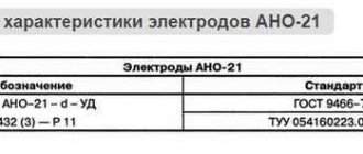
We recommend reading Description of ANO-21 electrodes
To calculate the specific value, multiply the optimal flow rate according to the rotameter (Рр) by the operating cycle time (T): Ру=Рр*T. If there are no table values, the last parameter is calculated manually using the formula T=(Vnm*60*1000)/(Kn*I), where:
- Kn – deposition coefficient;
- I is the current strength used for welding.
When creating connections, correction factors are used.
Below are the Kn values in g/Ah for different modes:
| I (A) | Wire diameter (mm) | ||
| 1,6 | 2 | 2,5 | |
| 200 | 14,2 | 12,2 | – |
| 300 | 16,5 | 13,5 | 11,1 |
| 400 | 21,1 | 16,8 | 13,9 |
| 500 | 28,3 | 22,3 | 17,8 |
When working with electrodes, use the formula T=60/V, where V is the speed of creating a welded joint. This parameter depends on the complexity of the operations performed and the method used. Structures are manually welded at a speed of up to 15-20 m/h. Using an automatic machine increases V to 100 m/h or more.
The time spent on auxiliary operations according to the standards ranges from 0.05 to 0.2 minutes when working with consumable and non-consumable electrodes, respectively. The calculated flow rate should be adjusted when welding small parts. Performing these and other complex operations increases the consumption of inert gas by 15-20%. When planning deliveries, it should be taken into account that a standard 40-liter cylinder is filled with liquid carbon dioxide (25 kg) when refilling.
Upon transition to a gaseous state, this amount forms 507 liters of a protective inert environment.
Calculation of consumption when welding profiles
When welding a profile such as an I-beam, a channel, a profile pipe, and so on, the same standards are used as for welding sheet metal. Their methodology is given in the section HERE.
An important feature that should be taken into account is the duration of the process. The longer the seams and the longer the welding, the higher the percentage of metal waste, and, accordingly, the higher the losses.
Also, welding of metal structures often occurs at heights, which complicates the work process and increases losses. There is a simple pattern here - the more difficult it is for a welder to work, the more materials and time will be spent.
What does it depend on?
Costs for electrodes, welding wire, etc. used when connecting structural elements, electrical energy consumption is mainly affected by the cross-section of the weld.
In turn, this indicator depends on exactly how the welding is performed, how thick the metal is, and the quality of preparation of the parts.
Important! Even slight moistening of the electrodes sharply increases consumption, reduces the quality of the seam, and makes work more difficult. Store materials exclusively in a dry place, in packaging that prevents the ingress of water.
As a rule, the main characteristic - the leg of the seam, on which its cross-section depends, is determined by the project. From here the required diameter of the welding material, the strength of the welding current, etc. are determined.
If we carefully examine the electric welding process, we will be convinced that not all of the introduced metal is used. Some of it is evaporated by the arc flame, some is sprayed with familiar welding sparks.
A certain amount of metal is bound in the slag covering the seam, formed by molten coating and oxides. These losses are defined by the word “waste” .
Finally, the process technology itself involves holding the electrode. Accordingly, part of it remains unused. Such a piece is technically called a “cinder”; its length is about 50 mm . Part of these costs depends on the location and length of the seam. Losses are also higher when you have to weld many separate sections, for example, when welding reinforcement, than one long seam.
How to reduce consumption
To reduce losses of welding materials without compromising the quality of the resulting products, the following recommendations can be used:
- When purchasing large quantities, carry out incoming inspection and check the quality of the electrodes. This will identify low-quality materials that will be rejected or only partially used.
- Use semi-automatic and automatic welding methods where possible. When welding in a shielded gas environment, use gas mixtures containing helium and argon to reduce spatter.
- Carry out the process at constant current and use reverse polarity.
- Carry out the process at optimal conditions (without increasing the current strength) to reduce waste.
Write in the comments what you think affects consumption the most.
Factors influencing rod consumption
The rods melt during the welding process. Their material is transferred into the seam. The longer the work lasts, the more the product melts. After a certain period of time, new rods have to be used. Manual welding with an electric arc is characterized by rapid consumption of material.
Electrode consumption rates for pipeline welding depend on many factors. Among them are:
- diameter of the product used for welding. The larger the diameter of the rod, the slower the product will be consumed. For proper welding, the thickness of the rod must be selected in accordance with the thickness of the material that will be processed;
- gap between welded pipes. The wider the gap, the more rods will be spent connecting the pipes. The narrower the gap, the narrower it will be necessary to make a welding seam and, accordingly, the less products will be spent;
- current strength. The current strength greatly affects the consumption of rods. It should be selected in accordance with the thickness of the electrodes. If selected incorrectly, consumption may be increased. For example, if the current selected for a thin rod is too high, it will melt very quickly. In addition, with excessive current, increased metal spatter occurs, which also affects the service life of the rod. Too little current can also increase consumption, since to create a high-quality seam, in this case, you will have to use wide oscillatory movements, which also affects consumption;
- thickness of the workpiece metal. The higher the thickness of the element being processed, the deeper it is necessary to boil, which affects the time of use of the rod and, accordingly, the total consumption of the rods.
Before starting welding work, it is necessary to calculate the approximate consumption of products. This will allow you to prepare the required number of rods and ensure a non-stop welding process. The classification of electrodes will help you choose suitable products.
Practical calculation
Involves determining the mass of metal and carrying out welding test work. When they are completed, the cinder is measured, the voltage and current, and the length of the seam made are taken into account. Based on these data, the number of required electrodes for welding a seam of a certain length is determined.
An accurate calculation will be in the case when both the external data and the position angle when performing the main work remain similar to those that were during testing. To avoid inaccurate determination, the experiment is repeated three to four times. If this condition is met, the calculation will be even more accurate than when using formulas.
Theoretical calculation
Based on the use of various formulas. In practice, two types of calculations are most widespread:
- by coefficient;
- according to physical characteristics.
The first method covers various categories of consumables and is calculated by the formula: H = M * K, where M is the mass of the metal being welded, and K is the special additive consumption coefficient.
The second method is based on the characteristics of both the electrode used and the metal structure being welded, calculated by the formula: G = F * L * Weight of the wire, in which F is the cross-sectional area and L is the length of the weld.
If the first formula allows you to calculate the consumption, then the second formula allows you to calculate the mass of deposited metal. Both calculations are “tabular”, that is, they are based on standard indicators corresponding to certain brands of electrode, type of metal, and weld size.