steel gradeAnalogueRolled thicknessDesign resistance, RyUnknown—any210 MPaC235St3kp2 according to GOST 535-20052 - 20 mm230 MPa20.1 - 40 mm220 MPaS245St3ps5, St3sp5 according to GOST 535-20052 - 20 mm240 MPa20.1 - 30 mm230 MPaS255St3Gps, St3Gsp according to GOST 5 35-20054 — 10 mm250 MPa10.1 — 20 mm240 MPa20.1 - 44 mm230 MPaS275St3ps according to GOST 535-20052 - 20 mm270 MPaS285St3sp, St3Gps, St3Gsp according to GOST 535-20054 - 10 mm280 MPa10.1 - 20 mm270 MPaS34512G2S, 09G2S according GOST 19281-20142 - 10 mm335 MPa10.1 - 20 mm315 MPa20.1 - 40 mm300 MPaS345K10KhNDP according to GOST 19281-20144 -10 mm335 MPa
Pipe size - here you need to select the pipe size that you want to test for the specified loads.
Result
The weight of the beam is the mass of 1 linear meter of pipe.
W required - the required moment of resistance of the profile.
F max is the maximum deflection in centimeters that is permissible for a beam spanning a span of length L.
Strength calculation:
Wbeams - moment of resistance of the selected pipe according to GOST 30245-2003. If Wbeams > Wrequired, then the strength of the beam is ensured.
Margin - if in this column the value is with a minus (-), then the beam does not pass in terms of strength, and if with a plus (+), then it shows what percentage the beam has a margin of safety.
Deflection calculation:
Fbeams - deflection that occurs in the pipe being calculated under the influence of a standard load.
The margin is the same as in relation to the moment of resistance.
Preliminary Considerations
The load of beams can be distributed (“q” in diagrams 3,4,5,9,15, etc.) or concentrated (“P” in diagrams 1,2,6,7,8, etc.).
Beam fastening can be:
- cantilever with rigid termination of one of the ends (for example, schemes 1,2,3 and others);
- “embedding - embedding”, when both ends of the pipe beam are rigidly clamped (embedded), schemes 6, 7, 8, 9;
- “hinge - hinge” (diagrams 12, 13, 14, 15 and others), with the left hinge being fixed and the right hinge being movable;
- “sealing - hinge” (schemes 9, 10, 11 others).
The rigid seal prevents the pipe beam from turning and moving in any direction. A fixed hinge only allows rotation of the pipe at the mounting location in a vertical plane.
The movable hinge allows the pipe to rotate at the attachment point in a vertical plane and move along its own axis. These movements are very insignificant and are a consequence of pipe deformation under load.
The rigid seal of the pipe prevents it from turning or moving in any direction. A fixed hinge only allows rotation of the pipe at the mounting location in a vertical plane.
The movable hinge allows rotation at the attachment point in a vertical plane and movement along its own axis. These movements are very insignificant and are a consequence of the deformation of the pipe beam under load.
The main type of this deformation is its deflection, the magnitude of which, along with the applied load, also depends on its length, the dimensions of its cross section and the physical characteristics of the material, in this case, on its elastic modulus (“E”). The modulus of elasticity of carbon steel is (2-2.1) * 10 ^ 5 MPa; alloyed (2.1 – 2.2) * 10 ^ 5 MPa; therefore, the calculator uses an average value of 2.1 * 10 ^ 5 MPa, which is 2,142,000 kg.cm2.
From the dimensional characteristics of the cross section of the pipe, the moment of inertia of the section (“I”) is used to calculate the deflection; the amount of deflection also depends on the position of the pipe point being checked relative to the supports.
The permissible deflection value of beams is determined by their purpose and place in building structures and is regulated by the relevant SNiP; in mild cases it should not exceed 1/120 - 1/250 of the pipe length.
Therefore, it is strongly recommended to check the calculation results for acceptability.
The purpose of the calculator to determine the bend
Wood is the most widely used material for creating frames for various buildings. From it, like from plasticine, you can create a design of any complexity. However, not the last place is occupied by such structural material as various metal profiles.
They are distinguished by such properties as plasticity, durability and strength. Not the last place among such materials is occupied by profile and round pipes. Try to imagine a carport made from a profile pipe coated with polycarbonate and the same structure from a corner.
It seems there can be no two opinions. And any pipe beam in the structure must be calculated. This is necessary for two reasons:
- Obtain an object with a sufficient margin of safety under the influence of its own weight, as well as wind and snow loads.
- Select the minimum profile acceptable for the building in order to minimize the cost of materials.
To achieve this goal, you need to use our online calculator and calculate the bending of a pipe beam. This is the case if the part is fixed on one side (cantilever). If both ends are fixed, you will need to calculate the pipe for deflection.
In this case, the following circumstances must be taken into account:
- Dimensions and cross-section: (profile or round). For a profile rectangular pipe, the calculation is made taking into account the direction of impact. When calculating beams made from a square pipe, this factor is the same for any direction of influence.
- Strength characteristics of the material, taking into account the wall thickness and grade of material. This is especially true when using beams made of round pipes, the calculation of which largely depends on the specified characteristics due to the variety of materials used.
Changing the configuration of pipes made of non-ferrous metals
Non-ferrous metals have a very useful property - high ductility.
However, they are not strong enough. During the bending process, as a result of the application of compression and tension forces, the pipe may collapse or rupture. To prevent this from happening, you must strictly follow the technology. Any metal has its own point of resistance, that is, the maximum and minimum load that it can withstand.
https://www.youtube.com/watch?v=QObQZfhQPR0
If you put too much pressure on the metal, it can cause deformation, unnecessary deflections or breaks in the profile. When calculating pipe bending, it is necessary to take into account such important characteristics as metal density, dimensions and diameter of profile or round pipes, as well as a number of other parameters. Thus, it will be possible to predict how effective the use of a particular material will be under environmental conditions.
During pipe bending, the inner layer of metal is compressed and becomes smaller, while the outer layer, on the contrary, increases due to stretching. But the central layer of metal remains unchanged, maintaining the original parameters, thereby ensuring the strength of the pipe.
Types of probable loads
How can you classify the loads on a pipe beam? In accordance with SP 20.13330.2011 “Loads and impacts”, the loading moments of a structure can be distributed according to the following criteria:
- constant - the pressure and weight of which do not change over time, such as the dead weight of the structure;
- temporary long-term, taking into account the weight of additional structures, including equipment, furniture, etc.;
- short-term transverse, depending on external operating conditions - loads from wind, snow or rain, to determine which we make our own calculations, depending on the area where the object is located. Such loadings under extreme conditions create conditions under which deflection of a pipe beam is possible.
- special impact conditions, which may include the impact of a car during parking, as a result of which the support may bend;
- seismic - for areas with certain seismic activity.
The strength of the ceiling determines the level of safety of living on a country site or in a village house.
The degree of loading of structures can be selected using tables, taking into account:
- the value of the moment of inertia indicated in the standards;
- span length;
- load size;
- Young's modulus (reference data).
The tables provide ready-made data calculated using a special formula, for example, for round, square and rectangular profiles. All strength calculations of load-bearing structures are, by definition, difficult to perform and require special engineering training in the field of strength of materials. Therefore, it is better to use a special online calculator. To calculate the loads, it is enough to enter the initial data into the table and at the output you can get an accurate result quickly and without much difficulty.
A beam truss, calculated in this way, will be a reliable structure for a long time. With correct calculation, the maximum rigidity of the floor is guaranteed.
How to calculate the load on a profile pipe
When choosing a profile pipe for load-bearing structures on their own, the customer understands the importance of accurate calculations of parameters and load. In this article we will try to figure out whether it is worth saving on calculations.
Profile pipes for high loads
With the arrival of summer, the construction season begins for companies, owners of cottages and summer cottages. Someone is building a gazebo, greenhouse or fence, other people are re-roofing or building a bathhouse. And when the customer has a question about load-bearing structures, more often the choice is made on a profile pipe due to its low cost and bending strength with low weight.
Bending pipes without radius
When creating a spatial frame, designers are faced with the need to manufacture elements in which it is necessary to create parts where sections of pipes are connected to each other at a right angle (90 degrees) or at an acute angle (45 degrees, for example). You can cut the pieces and then weld them together. However, the issue can be solved in another way:
- Make markings for the future cutout.
- Cut out excess metal.
- Perform a bend, connecting the edges of the cut made. Weld the metal along the edges.
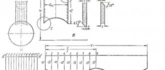
Scheme of the technical process of bending at right angles with trimming: 1 – marking; 2 – cutting out excess metal; 3 – bending and welding of edges
This method will allow you to obtain a fairly strong part, in which part of the metal remains intact.
If you do not trim, then the excess metal has nowhere to go. The result is an unattractive appearance of the product.
Direct bending of a profile pipe without trimming
What is the reason for this phenomenon? To understand how simple bending occurs, you should consider the diagram.
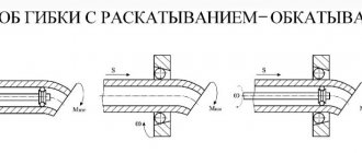
Scheme of bend formation in pipes
If a suitable mandrel is available, bending is performed:
- One end is fixed motionless.
- The surface of the workpiece rests against the base surface, relative to which the second end will be moved.
- Force is applied and a new surface is formed.
Inside you can see the central line along which the pipe is bent.
Similar phenomena occur not only in hollow products. Even in solid parts, when layers are displaced relative to each other, similar phenomena occur.
What load acts on the profile pipe?
Another question is how to calculate the dimensions of a profile pipe so as to get by with “little expense” and buy a pipe suitable for the load. For the manufacture of railings, fences, greenhouses, you can do without calculations. But if you are building a canopy, roofing, canopy, you cannot do without serious load calculations.
Every material resists external loads, and steel is no exception. When the load on the profile pipe does not exceed the permissible values, the structure will bend, but will withstand the load. If the weight of the load is removed, the profile will return to its original position. If the permissible load values are exceeded, the pipe becomes deformed and remains that way forever, or breaks at the bend.
To eliminate negative consequences, when calculating a profile pipe, consider:
- dimensions and cross-section (square or rectangular);
- structural stress;
- steel strength;
- types of possible loads.
Classification of loads on a profile pipe
According to SP 20.13330.2011, the following types of loads are distinguished by duration of action:
- constant, the weight and pressure of which does not change over time (the weight of parts of the building, soil, etc.);
- temporary long-term (weight of stairs, boilers in a cottage, plasterboard partitions);
- short-term (snow and wind, weight of people, furniture, transport, etc.);
- special (earthquakes, explosions, car impact, etc.).
For example, you are building a canopy in the courtyard and using a profile pipe as a supporting structure. Then, when calculating the pipe, take into account possible loads:
- canopy material;
- snow weight;
- strong wind;
- possible collision of a car with a support during unsuccessful parking in the yard.
To do this, use SP 20.13330.2011 “Loads and impacts”. It contains maps and rules necessary to correctly calculate the profile load.
Calculation diagrams of the load on a profile pipe
In addition to the types and types of load on the profiles, when calculating the pipe, the types of supports and the nature of the load distribution are taken into account. The calculator calculates using only 6 types of calculation schemes.
Maximum loads on profile pipe
Some readers wonder: “Why do such complex calculations if I need to weld a porch railing?” In such cases, there is no need for complex calculations taking into account the nuances, since you can resort to ready-made solutions (Tables 1, 2).
Table 1. Load for square profile pipe
| Profile dimensions, mm | Maximum load, kg, taking into account the span length | |||||
| 1 meter | 2 meters | 3 meters | 4 meters | 5 meters | 6 meters | |
| Pipe 40x40x2 | 709 | 173 | 72 | 35 | 16 | 5 |
| Pipe 40x40x3 | 949 | 231 | 96 | 46 | 21 | 6 |
| Pipe 50x50x2 | 1165 | 286 | 120 | 61 | 31 | 14 |
| Pipe 50x50x3 | 1615 | 396 | 167 | 84 | 43 | 19 |
| Pipe 60x60x2 | 1714 | 422 | 180 | 93 | 50 | 26 |
| Pipe 60x60x3 | 2393 | 589 | 250 | 129 | 69 | 35 |
| Pipe 80x80x3 | 4492 | 1110 | 478 | 252 | 144 | 82 |
| Pipe 100x100x3 | 7473 | 1851 | 803 | 430 | 253 | 152 |
| Pipe 100x100x4 | 9217 | 2283 | 990 | 529 | 310 | 185 |
| Pipe 120x120x4 | 13726 | 3339 | 1484 | 801 | 478 | 296 |
| Pipe 140x140x4 | 19062 | 4736 | 2069 | 1125 | 679 | 429 |
Table 2. Load for a rectangular profile pipe (calculated on the larger side)
| Profile dimensions, mm | Maximum load, kg, taking into account the span length | |||||
| 1 meter | 2 meters | 3 meters | 4 meters | 5 meters | 6 meters | |
| Pipe 50x25x2 | 684 | 167 | 69 | 34 | 16 | 6 |
| Pipe 60x40x3 | 1255 | 308 | 130 | 66 | 35 | 17 |
| Pipe 80x40x2 | 1911 | 471 | 202 | 105 | 58 | 31 |
| Pipe 80x40x3 | 2672 | 658 | 281 | 146 | 81 | 43 |
| Pipe 80x60x3 | 3583 | 884 | 380 | 199 | 112 | 62 |
| Pipe 100x50x4 | 5489 | 1357 | 585 | 309 | 176 | 101 |
| Pipe 120x80x3 | 7854 | 1947 | 846 | 455 | 269 | 164 |
Using ready-made calculations, remember that tables 2 and 3 indicate the maximum load under which the pipe will bend but not break. When the load is removed (the strong wind stops), the profile will regain its original state. Exceeding the maximum load even by 1 kg leads to deformation or destruction of the structure, so buy a pipe with a safety margin that is 2 to 3 times the maximum value.
We carry out pipe deflection calculations ourselves
Profile pipes are common in industrial and private construction. They are used to construct outbuildings, garages, greenhouses, and gazebos. The designs can be either classically rectangular or ornate. Therefore, it is important to correctly calculate the pipe for bending. This will maintain its shape and ensure the structure’s strength and durability.
Properties of bendable metal
Metal has its own point of resistance, both maximum and minimum.
Maximum load on the structure leads to deformations, unnecessary bends and even breaks. When making calculations, we pay attention to the type of pipe, cross-section, dimensions, density, and general characteristics. Thanks to this data, it is known how the material will behave under the influence of environmental factors.
We take into account that when pressure is applied to the transverse part of the pipe, stress arises even at points distant from the neutral axis. The zone of most shear stress will be the one located near the neutral axis.
During bending, the inner layers in the bent corners are compressed and reduced in size, and the outer layers are stretched and lengthened, but the middle layers retain their original dimensions after the end of the process.
Bend pipes are widely used in daily life
How to make the right calculations
Calculation of a profile pipe for deflection is the determination of the degree of maximum stress at a specific point on the pipe.
Each material has normal stress indicators. They do not affect the product itself. To make the calculations correctly, you must apply a special formula. It is necessary to ensure that the indicators do not exceed the maximum permissible values. According to Hooke's law, the resulting elastic force is directly proportional to the deformation.
When calculating bending, it is also necessary to use the stress formula, which looks like M/W, where M is the bending indicator along the axis on which the force falls, but W is the bending resistance indicator along the same axis.
The pipe bend must be correct and precise
Bending process
Bending creates a certain degree of stress in the metal walls. Tensile stress is obtained in the outer section, and compressive stress in the inner section. Due to these influences, the tilt of the axis changes.
During the bending process, the cross-sectional shape changes at the bent point. As a result, the ring profile takes on an oval shape. A clearer oval shape is visible in the middle of the deflection, but towards the end and beginning the deformation decreases.
For pipes with a cross-section of up to 20 mm, the ovality in the deformed area should not exceed 15%. For pipes with a cross-section of 20 and larger - 12.5%.
Please note that folds may appear in the concave area of thin-walled products. They, in turn, negatively affect the functioning of the system (they reduce the permeability of the working medium, increase the level of hydraulic resistance, and the degree of clogging).
Curved pipes are used in industry and private construction
Allowable pipe bend radii
According to state standards, pipes have a minimum bending radius.
If bending is carried out by heating and filling with sand, the outer diameter of the pipe is at least 3.5DN.
Forming a pipe on a pipe bending machine (without heating) – at least 4DN.
Folding when heated with a gas burner or in an oven to obtain half-corrugated folds is possible with an indicator of 2.5DN.
If the bend is intended to be steep (for bent sewer branches made by hot drawing or stamping) - no less than 1DN.
The pipe bend may be less than the specified values. However, this is possible if the production method ensures that the pipe walls are thinned by 15% of the total thickness.
We carry out calculations of pipe bending strength responsibly.
Bending pipes of various diameters
Formulas and tables
To calculate pipe deflection, we determine the length of the part. It is calculated using this formula:
L=0.0175∙R∙α+l
R is the bending radius in mm;
α – angle value;
I – a straight section of 100/300, necessary for gripping the product (when working with the tool).
When calculating the bending of a profile pipe, we take into account the size of the element being bent. It is determined by the following formula:
А=π∙α/180(R+DH/2)
The value of the number π = 3.14;
α – bending angle in degrees;
R – radius value (the value is taken into account in mm);
DH is the diameter on the outside of the pipe.
The minimum bend radii for copper and brass products are given in the table. The data corresponds to State Standards No. 494/90 and No. 617/90. In addition, the values for the outer diameter and the minimum length of the statically free part are also given here.
Bending of profile pipes can be performed on special machines
| External diameter | Minimum bend radius | Minimum free length |
| 3 | 6 | 10 |
| 4 | 8 | 12 |
| 6 | 12 | 18 |
| 8 | 16 | 25 |
| 10 | 20 | 30 |
| 12 | 24 | 35 |
| 15 | 30 | 45 |
| 18 | 36 | 50 |
| 24 | 72 | 55 |
| 30 | 90 | 60 |
The following table will help you calculate a round pipe for bending. It includes data related to steel analogues (indicators correspond to State Standard No. 3262/75).
| Pipe sizes | Minimum bend radius | Minimum free length | ||
| Conditional pass | External diameter | Hot | Cold | |
| 8 | 13,5 | 40 | 80 | 40 |
| 10 | 17 | 50 | 100 | 45 |
| 15 | 21.3 | 65 | 130 | 50 |
| 20 | 26.8 | 80 | 160 | 55 |
| 25 | 33.5 | 100 | 200 | 70 |
| 32 | 42.3 | 130 | 250 | 85 |
| 40 | 48 | 150 | 290 | 100 |
| 50 | 60 | 180 | 360 | 120 |
| 65 | 75.5 | 225 | 450 | 150 |
| 80 | 88.5 | 265 | 530 | 170 |
| 100 | 114 | 340 | 680 | 230 |
In order not to make mistakes in the calculations, you should also take into account the diameter and wall thickness of the pipes.
| Pipe diameter (mm) | Minimum bend radius taking into account wall thickness | |
| thickness up to 2 mm | thickness more than 2 mm | |
| 5/20 | 4D | 3D |
| 20/35 | 5D | 3D |
| 35/60 | 6D | 4D |
| 60/140 | 7D | 5D |
Manual hydraulic pipe bender
DIY pipe bending
If you do the bending yourself, calculating the pipe for bending will help, the formula of which is simple and universal (this is 5 pipe diameters).
Let's calculate the bend on a part with a cross section of 1.6 cm.
1st step: you need to clearly understand what kind of circle the result will be (one fourth of the circle is needed for correct bending).
Step 2: determine the radius - multiply 16 by 5. Result - 80 mm.
3rd step: calculation of starting points for bending. To do this, use the formula C=2π∙R:4. Value C is the length of the pipe that will be used in the work. Two pi numbers are used, as well as an indicator of the outer radius of the pipe.
4th step: values are replaced with known data: 2∙14∙80:4. The result is 125 mm. This will be the length of the section where the minimum bending radius will be 80 mm.
Methods for calculating loads on a profile pipe
To calculate loads on profiles, the following methods are used:
- load calculation using lookup tables;
- using the stress formula when bending a pipe;
- determining the load using a special calculator.
How to Calculate Load Using Lookup Tables
This method is accurate and takes into account the types of supports, the fastening of the profile to the supports and the nature of the load. To calculate the deflection of a profile pipe using lookup tables, the following data is required:
- the value of the moment of inertia of the pipe (I) from the tables GOST 8639-82 (for square pipes) and GOST 8645-68 (for rectangular pipes);
- span length value (L);
- pipe load value (Q);
- the elastic modulus value from the current SNiP.
These values are substituted into the desired formula, which depends on the mounting on the supports and the distribution of the load. For each design load scheme, the deflection formulas change.
Calculation using the formula for maximum stress when bending a profile pipe
The calculation of bending stress is calculated using the formula:
where M is the bending moment of force, and W is the resistance.
According to Hooke's law, the elastic force is directly proportional to the amount of deformation. Now substitute the values for the desired profile. Further, the formula is clarified and supplemented based on the characteristics of the steel for the profile pipe, load, etc.
Yulia Petrichenko, expert
Calculator for calculating the load on a profile pipe
Calculating a profile pipe for deflection is a complex and time-consuming process. To do this, you need to carefully study GOSTs and other regulatory documents, study the types of supports and loads on the future structure, build a diagram, add a safety margin. The slightest mistake in calculations will lead to a sad ending. Therefore, without knowing physics and Sopromat, it is better to entrust the calculations of critical structures (roofing, frame) to professionals. They will help you make accurate calculations at lower costs.
If you have solved the issue of calculating the load on a profile pipe, share your experience and tell us why you used it in the comments!
Pipe bending methods
In addition to profile steel pipes, sometimes it becomes necessary to use other materials. If you need to make a distiller, then use:
- copper tube. It's easy to bend. Plastic material easily takes the desired shape;
- glass tube. The process is quite complex; heating to a temperature of 1000…1100 ⁰С is required. The tube is compressed around a mandrel heated to a temperature of 1100...1200 ⁰C (special steels containing titanium are used).
Flexible materials: Border tape for beds and lawns
Arcs for a small greenhouse can be bent from a metal-plastic pipe. There is no need to use special equipment. Two people, helping each other, can give the desired radii and shape to such material.
Based on the required bend angle, material and diameter of the pipe, bending can be done manually or using special equipment. There are also hot and cold bending, with and without filling the pipe cavity.
Here is a diagram, formulas and recommendations for calculating pipe bending parameters, following which is a guarantee of a good result
After the load is removed, a phenomenon called springing occurs, which is directly proportional to the elastic modulus of the material. The amount of possible deformation also depends on the bending method used and the geometry of the object.
Relatively recently appeared methods are bending pipes using industrial and high frequency currents and bending with tension. In the first case, a high-performance high-frequency installation is used, in which a pipe with a diameter of 95 - 300 mm is heated, bent and cooled.
It consists of two parts - a mechanical one in the form of a bending machine and an electrical one, which includes an electrical part and a high-frequency installation.
The pipe is deformed only in the heated area located in the inductor zone. The geometry changes to a given size under the influence of a deflecting roller. Using this method, you can obtain a bend with a small radius curvature.
Bending using the second method is carried out on bending and stretching machines, which include a rotary table. The pipe is subject to large tensile and bending forces. This is how steeply curved bends are obtained with a constant wall thickness along the entire circumference.
The method is used for bending large-diameter pipes used in the aviation, automotive, and shipbuilding industries, where high demands are placed on the pipeline. The advantage is the ability to bend pipes with a wall of 2 - 4 mm by 180⁰.
What load acts on the profile pipe?
External mechanical forces act on the profiled pipe: the weight of structures, the weight of snow, wind influences, etc.
Moreover, each product has a maximum resistance value. For example, an indicator of the load that a profile can withstand in bending. When the maximum value is reached, the structure loses strength and begins to deform until it breaks.
This value must be accurately determined at the design stage of installation work. It is calculated by calculation methods, using reference information, the purpose of which is to help determine the necessary profile parameters: cross-section, metal thickness. The initial data in this case are the strength characteristics of the material and the types of upcoming loads.
Load classification
Experts have developed rules for determining loads and their effects - SP 20.13330.2011. They contain a classifier of the types of action of external forces on structures erected by humans.
Depending on the time of exposure, loads are divided into permanent and short-term. In addition, a special category of manifestation of external forces (fires, explosions, earthquakes and other emergencies) has been identified.
The permanent ones include:
- The weight of structures and structures that exert pressure on the base of the profile throughout the entire period.
- Weight of equipment and manufactured products located in structures.
- The severity of embankments and other layers of soil, earthen and mountainous hills.
- Water pressure.
Short-term loads included:
- The weight of equipment used during repair, maintenance, and replacement.
- Loads from transport and loading equipment, people employed in temporary work.
- Exposure to natural forces (wind, snow, rain, temperature changes).
Maximum loads
To select the correct pipe for use, you need to know the maximum weight that the beam or support must support in a given location.
This quantity is expressed as a concentrated force applied at the center of the span.
Under the pressure of the specified force, the beam will bend, but after the end of the impact it will return to its previous state (in the photo). Exceeding the highest value will break the carrier.
In everyday practice, a distributed load is often encountered, uniformly affecting the entire length of the beam.
This suggests the conclusion that spans should not be too large. Installing a powerful beam can cover its advantages at the cost of the issue and the overall weight of the structure. It makes more sense to install additional supports, which allows you to increase the permissible weight on the floor.
To determine the magnitude of the maximum loads, you can use various reference data on the Internet.
Allowable bend radii based on material strength
The bending radius of the profile depends on the external section DN, the thickness of the material, its density and flexibility.
State standards establish minimum bending radii for profiled pipes. Their permissible size is largely determined by the way the part is bent.
- If the bend is made by heating the workpiece, or by filling it with sand, the bend radius must be at least 3.5 DN.
- Bending on bending equipment without heating is possible with a minimum radius of 4 DN.
- If the process uses furnace heating, a value of 2.5 DN is allowed.
- An important condition for bending is the thinning of the walls of the product in the area of operation by no more than 15%.
Bending pipes along a certain radius with preliminary cutting of grooves
You can often hear the desire to bend a profile pipe by cutting and welding grooves. The process is carried out in the following sequence.
- A cross cut is made on three sides of the pipe. The fourth side is not damaged.
- The inner layer is shifted until the extreme points of the cuts touch.
- After completing the bending along the cuts, welding is performed.
Scheme of the technological process of bending along cuts
Load design diagrams
The process of calculating any profile begins with the selection of a design schematic model.
Before starting calculations, collect the load that will act on the floor.
Then a diagram is drawn taking into account the loading pattern and beam supports.
Next, using the specified parameters and information from the assortment tables given in GOSTs, the corresponding calculations are made.
For their simplicity and efficiency, you can use online calculators that are equipped with programs with ready-made formulas.
How to find out if the calculations are correct?
Each material, including the metal from which rectangular pipes are made, has a normal stress rating. The voltage encountered in practice should not exceed this value. It is also necessary to take into account that the elastic force is less, the greater the loads applied to the pipe.
In addition, you need to take into account the M/W formula. Where the bending moment of an axle acts on the bending resistance.
To obtain more accurate calculations, a diagram is drawn, that is, an image of a part that maximally reflects the features of a given part, in this case, a rectangular pipe.
Load calculation methods
The following methods are used to determine permissible loads:
- Using an internet calculator.
- Based on lookup tables.
- According to the formulas for stress during profile deflection.
Before making calculations, it is recommended to draw up a drawing of the future frame and decide on the types of loads.
If the part is attached at one end, the element is calculated for bending. When mounted on supports, the deflection is calculated.
Using lookup tables
The option with tables of already calculated maximum load is the simplest and most convenient for a person unfamiliar with strength materials and calculations. They contain ready-made calculation results for specific types of profile elements.
For square profiles
For rectangular beams
The user immediately sees the limit value that a pipe with certain parameters can withstand at a given span length. Can independently compare and analyze data and choose the best option.
For example, a 40×40 square profile with a material thickness of 3 mm in a span of 2 m will support 231 kg of weight. If the distance between the supports increases to 6 m, the permissible load will be only 6 kg.
Calculations are made taking into account the weight of the pipe itself, the magnitude of the load is depicted by the concentrated force applied at the mid-span point.
For independent calculations, use data from GOST reference tables. Thus, the moment of inertia parameter for a square profile is taken from GOST 8639-82, for a rectangular section - from GOST 8645-68.
Calculation using the formula for maximum bending stress
To calculate a profiled element for bending, use the formula
Here M is the magnitude of the bending moment of force, and W is the sectional moment of resistance.
It is clear from the formula: the larger W, the lower the stresses that arise in the section of the beam.
To obtain the M value, it is necessary to know the span length and the degree of deformation of the material. The last value is found in the assortment tables of the corresponding GOSTs.
To calculate the parameter W, the dimensions of the beam will be required. The resulting values are entered into the formula.
Features and properties of profile products
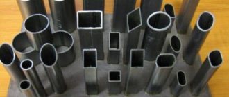
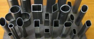
Profile are pipes that have a cross-section that is different from circular. The most common options are rectangular and square products. As already mentioned, the particular popularity of this type is associated with one of its key advantages - the design will be lightweight.
Moreover, the specific shape greatly simplifies attachment both to each other and to other surfaces. This type of building products, according to GOST, is made from a wide range of metals and alloys. However, the most commonly used are steel profiled pipes made of carbon and low-alloy steel.
Every metal has an important natural quality - a point of resistance. It can be either minimum or maximum. The latter, for example, causes deformation of erected structures, leads to kinks and, as a consequence, to fractures.
When bending, it is important to evaluate such characteristics as size, cross-section, type of product, its density, as well as the rigidity of the material and its flexibility. Knowing all these general properties of the metal, you can understand how the structure will behave during operation.
It is important to remember that when you bend the product, the internal parts of the structure are subject to compression, their density increases, and they themselves decrease in size. The outer layer, accordingly, becomes longer, less dense, but more stretched.
At the same time, the middle sections retain their original characteristics even after the process is completed. Hence, you should always remember that during the bending process, tension will certainly arise even in areas located as far as possible from the neutral zone. The maximum pressure will be in those layers that are very close to this very neutral axis.

