18.03.2020
- Device and characteristics
- The principle of operation of the spindle and what it consists of
- Spindle use: what is it for?
- Classification of spindles by type, size and diameter
- Spindle type selection
- Selecting the type of cooling
- Selecting speed and power
- How to make your own spindle from a picture
- Service
Have you been involved in metalworking for a long time or are you just starting to study the theory? We will help you understand the basic skills. In the article we will talk about the machine spindle: what it is, show a photo of the tool holder and talk about how to work with it.
Detailing of main components
The bed is designed for the correct and stable location of the main components (headstocks) during any load during operation. In metal-cutting machines, the bed can have a vertical or horizontal position. Basic requirements for a frame of any design:
- vibration resistance;
- rigidity;
- heat resistance.
Many types of machines are equipped with a traverse or cross beam that moves on vertical rails. The traverse has horizontal rails along which mobile units move. This mechanism is equipped with longitudinal milling, rotary turning, planing, radial drilling machines. Two-column vertical turning lathes are additionally equipped with a portal - a crossbar between the upper points of the racks. The portal gives the structure additional rigidity.
Guides are of great importance for the accuracy of parts; mobile units move along them.
There are several types of guides:
- rolling;
- slip;
- combined.
The guides wear out quickly, so increased attention is paid to the selection of material and manufacturing of these units. Gray cast iron, steel, bronze, plastics, composites are used
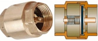
Spindle unit
spindle assembly of a machining center
This mechanism is one of the most important in a lathe; it provides the main movement - cutting. The spindle assembly is located in the headstock and can have a different design.
Main parameters of the headstock spindle assembly:
- accuracy - determined by the degree of runout, which must be within certain limits. The runout values are set taking into account the accuracy class;
- Vibration resistance is the main dynamic unit that causes vibrations of the headstock and the entire machine. Vibration resistance is determined by the oscillation frequency of the spindle end and should be more than 600 Hertz for particularly precise models, and more than 250 Hertz for ordinary ones;
- stiffness - being a component of the supporting system, the spindle affects the total stiffness;
- Heat Resistance - The spindle supports located in the headstock are the main source of heat generation in the machine. From the supports, heat gradually spreads along the walls of the headstock, causing it to skew relative to the base;
- durability - it depends mainly on the type of support and determines the life of the spindle without loss of accuracy.
Video about the exact dimensions of components and parts of a lathe:
Device and characteristics
Metal processing on machines has become widespread. This is not surprising, with the advent of mechanized equipment, labor productivity has increased significantly, and the process of manufacturing metal products has become much simpler - workers spend less time on one production cycle.
The creation of machine tools also provided:
- Higher quality parts, good accuracy class.
- Reducing the final cost of all work.
- Increased production speed.
Almost no machine tool can operate without spindle locking – we’ll explain this using the example of a lathe. This is an element that is responsible for strong and reliable installation of the workpiece in one place. If we take a turner as an example, he attaches a metal bar or shaft between two headstocks, on one side of which such a holder is installed. The second very simple illustration is a drill. Here, in order to hold a drill or other tool, you also need to mount it inside the spindle.
The word itself is of German origin. Spindel is a spindle, that is, something that has the ability to rotate in different directions. Structurally, it is a shaft. The term itself is mainly used in such areas as machine tool building, metalworking and woodworking, respectively. This is an extremely important element; without it, the operation of not a single device can be imagined. The task of the part is to transmit the force generated by the electric motor to the workpiece made of metal, wood, or plastic. A device for centering and clamping this bar is attached to the shaft.
Let's explain again with a simple example to understand that there are two main purposes - to rotate and to hold the workpiece. A lathe has a spindle. A gear is attached to one side, through which force is transmitted. A bearing is located at the second edge of the shaft. A clamp chuck is attached to it.
But, it would seem, why else is it needed if you can attach a metal or wooden sample directly to the gearbox or gearbox? The fact is that these parts of the machine are not adapted to increased vibrations and high loads; they will simply break under them. But the shaft can become an intermediary, which takes on all mechanical (and thermal) influences. In addition, on one side there is a cartridge that has fastening elements - threads, splines, grooves, that is, they are universally suitable for the specific purpose of the fastener.
What are the features of the spindle device:
- Fastening is carried out using a rolling bearing. This is a durable unit, standard, but it also has different designs. For example, some may be vibration resistant, while others may be cheaper. Machines equipped with a cooling and lubricating fluid supply system work much better, because in this case the bearings experience less stress and friction, thereby significantly increasing their service life.
- The shaft receives its main rotational movement from an asynchronous motor. It is installed in the equipment housing - usually in the right headstock. At first, electric motors were powered only from three-phase sources and were installed directly in factories. They were believed to have higher power. But now they produce equipment that is powered by 220 V, so it can be placed under normal conditions - often turning or milling machines are located in garages and other “home” buildings for personal use.
- The spindle can receive rotational motion directly from the electric motor, but more often through an additional component, such as a belt. The belt drive is convenient - this part is inexpensive, easy to attach, and also easy to use, but at very high speeds it can slip. In such cases, when high speed is needed, gears and gears are installed.
- The main fastener, which is located at the edge of the shaft, is the collet chuck. This allows for reliable fastening of a shank of any diameter. Almost all tools for metal cutting and drilling are equipped with such a tip (tail), and if not, then they have to be attached along the outer edge, which is much less reliable and allows for significant discrepancies and vibrations.
- It is very important in industrial production to have a cooling system on lathes or milling machines. It is of great importance - it extends the maximum period of operation, as well as the time of continuous metalworking.
- The most complex spindles are found in CNC equipment. The fact is that the presence of a numerical control panel makes it possible to manufacture parts with maximum accuracy. This, in turn, requires minimal vibrations. Such high-quality equipment can be ordered online on the company’s website. Here you can find high-quality machines for processing metal workpieces.
- The degree of shaft fixation directly depends on the rotation speed. The higher it is, the more securely the fastening should occur.
Nuances of choice
It is worth noting that spindles for CNC milling machines are more common than products for “simple” machines. There is nothing surprising here: such devices themselves have almost been supplanted. But you still need to immediately clarify whether the device is intended for working on metal or wood. Both household units in industry and industrial houses should not be used. Both of these only mean a waste of money. In any case, power comes first in selection.
Saving on it is strictly contraindicated. The greater the force applied, the longer the device will work (within certain limits, of course). Recommended values:
- for drilling and engraving work, an indicator of less than 600 W is enough;
- standard work with wood and metal sheets requires 0.8-1.4 kW;
- Daily CNC factory work requires a minimum of 1.6 kW.
Plywood and other panel wood materials are processed at powers of up to 3 kW, and solid wood, aluminum, bronze - up to 6 kW.
However, you should also understand that the milling itself can follow different scenarios. With the force method, the rate of rotation of the cutter far exceeds the intensity of the shaft movement. With high-speed, the cutting part itself does not move quickly, but is fed actively. Such approaches are used, respectively, with priorities for efficiency of work and quality of results. Of course, the spindle is selected of the appropriate class.
Selecting the type of cooling
Cooling of the rotation zone is required to increase service life. There are two types.
Water (liquid)
Differences:
- They are very quiet - the liquid flows almost silently. But at the same time there is another loud sound from the movement of the impeller.
- The presence of a circuit that includes a system of tubes, a container, and a pump. It is necessary to constantly monitor the moisture supply and its temperature.
- Can operate at low speeds.
Air
Distinctive features:
- Strong and not the most pleasant sound.
- Chips may fly away under the influence of a jet of air.
- It is necessary to clean the shirt where metal particles become clogged at regular intervals.
- It is required to monitor the temperature very carefully; ideally, install a sensor with a signal, because the entire device is very sensitive to overheating.
As a result, we recommend using the air option when working with soft materials, but when the workpiece is made of durable metal, it is better to use liquid cooling.
Main design features
A universal screw-cutting lathe consists of main structural units, which are standard elements. These include:
- caliper;
- bed;
- thrust and spindle headstock;
- electrical equipment;
- drive shaft;
- guitar gears;
- a box that provides selection and change of feeds;
- lead screw - it is this detail that distinguishes a screw-cutting lathe from a standard lathe.
Depending on some features, the accuracy of the machine may vary. Therefore, universal equipment can be of both accuracy class N and increased – P.
Front and rear stock
The headstock or spindle has the main role of fixing the workpiece in processing and transmitting rotation to the workpiece from the electric motor.
The spindle is located inside the body of the headstock. A speed control handle is mounted on the outside of the machine body. The tailstock or thrust is necessary to fix the workpiece.
Caliper
The support is designed to move the tool holder with the cutter in the longitudinal, transverse direction relative to the axis of the machine. The lower part of the support is called the slide or carriage.
After a certain time of operation of the machine, the support will need to be adjusted, since otherwise the processing speed will decrease. Adjustment for gaps consists of tightening the wedge strip.
Compared to other parts, the caliper is large. The choice of tool holder is determined by the class of the machine. For large equipment, be sure to secure the cutters with an additional four screws.
Gearbox
This is the main part of the spindle drive. It transmits engine energy to the rest of the machine. Another function is to change the spindle speed and the operating speed of the entire machine.
The box is built into the spindle head housing or in a separate housing block. The speed can be changed in a stepless or stepwise manner. The standard gearbox includes the following components:
- gear system;
- V-belt transmission;
- reversible electric motor;
- electromagnetic clutch with braking system;
- handle for changing gears.
The gearbox operates using gears.
Spindle
This is the main part of the machine, which is made in the form of a shaft with a conical hole for securing workpieces. To ensure that the part has high strength and durability, it is made of high-strength steel.
In the classic version, the spindle is made on high-precision rolling bearings. A special ring is installed on the support of the part, which ensures the accuracy of the machine.
There is a conical hole at the end of the structure. The spindle needs a cavity to install a rod that helps, if necessary, knock the center out of the seat.
The strength and durability of the spindle directly depends on the bearings available there.
bed
This is the main part of the machine, which is made using cast iron. All the most important parts and elements of this design are attached to it.
The frame itself consists of two steel beams. The beams, in turn, are connected to each other by stiffening ribs. Each beam has a connection to two guides.
The guides on both sides belong to the prismatic group. The flat-shaped guide is located inside on the left side.
Threading
There are several ways to cut threads using a screw-cutting lathe. For this, a die, tap, cutter and other types of tools are used.
With their help it is possible to cut internal and external threads
When using a cutter, it is important to fully comply with the technology. It includes:
- correct sharpening of the cutter;
- accurate adjustment of machine operating modes;
- using a template, correct installation of the cutter in the center of the part;
- measuring the resulting dimensions using gauges or templates.
In such work, defects in the form of sharp points, torn threads, scuffing and crushing are unacceptable.
Electrical control unit
The standard control unit for a screw-cutting lathe includes several handles and buttons:
- handle for setting the number of revolutions;
- control system for setting cutting surface parameters;
- handles for caliper control.
A CNC machine has a more complex structure, but can work without operator participation at intermediate stages.
Apron
In the apron of a screw-cutting lathe there are mechanisms that convert the rotational movement of the lead screw and the lead shaft into the translational movement of the caliper.
Spindle units MRS
Spindle units are the most critical mechanisms of machine tools. The accuracy of processing largely depends on the perfection of the design, as well as on the quality of manufacturing and assembly of the spindle assembly. In recent years, in the practice of machine tool building there has been a tendency to create rigid structures of spindles of relatively short length. Increasing the rigidity of spindles is achieved by increasing the diameter or cross-sectional area, using additional supports, increasing the rigidity of the rolling bearings by creating a preload, etc. For rotation drives of high-speed and precision machine tools, the spindles are made to relieve the pulleys of drive belts or gears from the action of the bending moment. The choice of the type of last gear on the spindle is very important. The inter-support distance for spindles of normal precision machine tools is taken equal to 4...5 diameters of the spindle in the front support. The rigidity j of spindles of light and medium-sized machines of normal accuracy, conventionally considered in the form of a beam on hinged supports with a force in the middle, must be at least 50 n/µm. For high-precision machines, j ³ 50 n/µm is taken. The drive gears of the spindles must be made to 6...7 degrees of accuracy, have a tight fit and be located directly at the supports.
Requirements for spindle units
The main criteria for the performance of spindle units are: geometric accuracy, rigidity, speed, durability, dynamic characteristics. The spindle rotation accuracy is assessed by the radial or axial runout of its base surfaces. The magnitude of this runout depends on the accuracy class of the machine and is regulated by the relevant GOST. So, for example, for normal precision lathes, the tolerance for radial and axial runout is 5...8 µm. The rigidity of the spindle assembly is determined by the elastic movements of the front end of the spindle under the action of cutting forces and is also regulated by GOST. The standard value of rigidity for machines of classes N and P is (50...70) n/µm. The maximum rigidity of a spindle assembly is mainly determined by the compliance of its supports. The speed of spindles is estimated by multiplying the spindle diameter d in the front support and the rotation speed n. For spindle units on rolling bearings, the speed indicator d´n is (2.5...3) 106 mm rpm. The durability of spindle assemblies is assessed by their service life in hours without loss of original geometric accuracy. The dynamic characteristics of spindles are assessed by vibration amplitudes on potentially unstable vibration modes. The higher the first natural frequency of vibration, the higher the stability of the dynamic system of the spindle assembly. The natural frequencies of spindle vibrations vary over a wide range (100...600) Hz and lead to the excitation of self-oscillations during cutting. Therefore, to ensure stable cutting, it is necessary to deliberately reduce cutting conditions and productivity.
Selecting spindle material
The spindles of normal precision machine tools are made of structural steel grades 45, 40X with surface hardening of the outer and inner seating surfaces to hardness HRse = 48...52. The spindles of precision machine tools, which have a more complex shape and operate under fluid friction conditions, are made of chromium-nickel, case-hardened steels of grades 18ХГТ, 12ХН3А, 20Х with hardening to hardness HRсe=56...60. For spindles of machine tools of complex shape with difficult induction heating, alloy steels of grades 40ХН, 40ХГР, 50Х, ШХ15, ХВГ with volumetric hardening to hardness НRсе=56...60 are used.
Spindle assembly design
The design of the spindle assembly largely depends on the type of machine, its accuracy class and the method of fastening the tool or workpiece. In order to be able to secure a tool or workpiece in a spindle, the shapes of the front ends of spindles of all types of universal drilling, boring and milling machines, including CNC machines with conical seating surfaces, are standardized according to GOST 24644-81. The shapes and dimensions of the front ends of the spindles of turning and grinding machines are established in accordance with GOST 12593-72 and GOST 2324-77. The design of the front ends of the spindles is shown in Fig. 2.39.
The designs of spindle units of metal-cutting machines are diverse. Spindle units are made of two-bearing and three-bearing types. As the analysis shows, the rigidity of two-support structures is slightly lower than the rigidity of three-support structures, provided that the distance between the supports of the two supporting spindles is close to optimal. Sometimes the installation of a third support is caused by the desire to increase damping in the spindle assembly. Since the production of three support spindle units is associated with significant technological difficulties, the vast majority of spindle units of metal-cutting machines are made of two support units. Only in heavy machines are three-support spindle units used. Unlike general purpose shaft supports, spindle supports must be preloaded. Preload is understood as the creation of minor contact deformations (2...5) μm of the rolling elements with the raceways of the bearing rings. Its main purpose is to increase the rigidity and accuracy of spindle units, especially in the area of light loads. Preload is usually created in each spindle support, with independent adjustment. The choice of the optimal scheme for its radial and axial fixation is important for the performance of the spindle assembly. All the variety of designs of spindle units can be fundamentally reduced to three main fixation schemes (Fig. 2.40):
rice. 2.40
In the first scheme, radial and two-sided axial fixation of the spindle is made in the front support. The rear support is floating, allowing you to compensate for linear thermal deformations of the spindle. The design of the front support uses special bearing designs: a double row with cylindrical rollers of the 3182100 series and two thrust bearings of the 8000 series. It should be noted that this design is characterized by increased complexity of the front support and high heat generation in it, which negatively affects the manufacturability of manufacturing and assembly, as well as on processing accuracy. In addition, due to the significant difference in the radial stiffness of the bearings of the 3182100 and 8000 series, the support design must provide for separate adjustment of the preload of these bearings, which requires large axial overall dimensions and special adjustment care. Therefore, this scheme is mainly used in medium-sized drilling, milling, boring and lathe machines. It should be noted that the use of thrust bearings in the front support significantly reduces the speed ( d × n ) of the spindle assembly. Therefore, in the spindles of light and high-speed machine tools, instead of thrust bearings, angular contact bearings of the 36000, 46000 series, etc., which have a higher speed, are installed. Transferring thrust (or angular contact) bearings to the rear support (Scheme 2) significantly simplifies the design of the front support and reduces heat generation in it, but at the same time the temperature deformation of the front end of the spindle increases sharply, which is unacceptable for high-precision machine tools. Therefore, scheme 2 can be recommended for turning operations, drilling, aggregate, grinding and other machines with low requirements for the accuracy of axial dimensions. Spindle units designed according to the third scheme have fairly high radial and axial rigidity. However, this scheme has a common disadvantage with the first scheme: the need for separate adjustment of the bearing preload and limited speed. In order to increase speed and reduce temperature deformations, we can recommend the use of 46000 series angular contact bearings in the design and the choice of a small inter-support distance. The scheme can be used in medium-sized machines (including CNC), with a small inter-support distance, or using axial spring compensators to select bearing clearances. The design of spindle supports is mainly carried out according to the first two schemes. As an example, let's consider a variant of the design of the spindle assembly of a lathe, made according to the second scheme (Fig. 2.41).
rice. 2.41
In this design, the radial clearance of bearing 2 is adjusted using nut 1 by displacing the inner ring of the bearing until it touches spacer ring 3. For ease of installation and dismantling, ring 3 is detachable, consisting of two half-rings. Nut 4 is designed to ensure the dismantling of ring 2 in order to reduce the preload. For the same purpose, hole 6 is used, into which oil is forced under high pressure to hydraulically release ring 2. The spring-loaded lock 7 serves to prevent spontaneous unscrewing of nut 1. The required amount of tension is ensured by grinding ring 3. It should be noted that the conical surface A of the spindle does not provide high precision of alignment, as a result of which skew of the inner ring of the bearing and loss of geometric accuracy of spindle rotation are possible. To eliminate this drawback, it is recommended to supplement the cone alignment with alignment at the end of the inner ring using a long spacer sleeve 5 with an H6/n6 fit. The long sleeve together with the H6/n6 fit ensures good axial direction of the ring.
Methodology for designing spindle supports.
It is recommended to design spindle supports in the following sequence:
- Selection of design (type) of bearings.
- Selection of bearing accuracy class.
- Selecting a fixation system.
- Selection of bearing fits.
- Selection of lubrication system and design of sealing devices.
Let us consider the content of the individual stages of designing spindle supports.
Selection of bearing design (type)
In the machine tool industry, a number of types of rolling bearings are used, specifically designed for installation in spindle units of machine tools. The following designs are of greatest interest. Double-row radial roller bearings with short cylindrical rollers of types 3182100 and 4162900 (Fig. 2.42).
rice. 2.42
Radial double-row roller bearings type 3182100 are the most common type of rolling bearings used in spindle units of domestically produced metal-cutting machines. These bearings, produced in extra-light series dimensions, have high load-bearing capacity, rigidity and speed. The presence of a conical hole at the inner ring (with a taper of 1:12) allows you to adjust the radial clearance in the bearing by axial movement of the inner ring relative to the conical journal of the spindle. In medium and heavy machine tools, another modification of the described bearings is used - bearings of type 4162900. They differ in that the smooth (without shoulders) raceway is not on the outer ring, but on the inner ring, and the outer ring is made with shoulders. This change in the design of roller bearings makes it possible to manufacture them in ultra-light series dimensions, especially suitable for installation in spindle units of boring machines and longitudinal milling machines. Tapered roller bearings of the “Gamet” type Bearings of the “Gamet” type (manufactured by “La presision industriell” in France and “Gamet” in England) are available in various designs: double-row tapered roller bearing with a collar on the outer ring or single-row tapered roller bearing with a collar on the outer ring and others. A distinctive feature of “Gamet” bearings is the special design of the cage, equipped with holes, which occupies almost all the free space between the raceways of the outer and inner rings, the use of hollow rollers: as a result, a system of channels is created through which lubricant circulates under the influence of centrifugal forces. Double-row “Gamet” roller bearings (Fig. 2.42) have a different number of rollers (there is one more roller in the front ring cage). This improves the dynamic properties of the bearing. The presence of a collar on the outer ring allows the use of a very convenient base in the form of a flat end of the spindle head during installation. The diameters of the holes in the inner rings of a double-row bearing (front and rear) are not the same; The diameter of the rear ring is several microns larger, which provides the necessary freedom of movement of the rear bearing ring when adjusting the clearance-preload. Thrust-radial double-row ball bearings type 234000. Double-row thrust-radial ball bearings type 234000 (Fig. 2.42) with a contact angle of 60 (manufactured by SKF Germany) are used for work in spindle assemblies of metal-cutting machines together with precision double-row bearings with short cylindrical rollers. Recently, special double-row tapered roller bearings of the 697900 series and single-row tapered bearings of the 177160 series have been used in spindle bearings. They have high rigidity and speed. The following two principles for choosing the type of bearings are generally accepted: 1. For high-speed, lightly loaded machines, ball bearings are used. 2. For medium and heavy machines with increased rigidity requirements, roller bearings are used. Based on the analysis of spindle bearing designs, the following basic requirements for their selection can be formulated: - high geometric rotational accuracy. - high rigidity, speed and durability. — the ability to create preload in the bearing. — simplicity of design, installation and the ability to adjust bearings. The totality of these requirements is sufficiently satisfied by bearings of the 3182100, 697900, 177160, 234000, Gamet, SKF and others series. The designer of spindle units needs to know the advantages and disadvantages of various types of bearings, since the quality of the spindle units depends on their correct choice; rotation accuracy, rigidity, speed, durability. In Fig. Figure 2.43 shows the most common types of bearings and the corresponding values of relative stiffness C. Bearings with tapered rollers (GOST 333-79, diagram 1 in Fig. 2.43) have the highest rigidity and minimum speed. The preload in the bearing is controlled by the relative displacement of the bearing rings. Bearings are recommended for use in spindle units with heavy loads - in milling, turning, boring and other machines.
rice. 2.43
Double-row roller bearings (GOST 7634-75, diagram 2 in Fig. 2. 43) are distinguished by high rigidity, speed, and durability. Preload in the bearing is provided by axial movement and radial deformation of the inner ring of the bearing. Angular contact ball bearings (GOST 832-78, diagram 3 in Fig. 2. 43) have maximum speed and lowest rigidity, so they are often used in a dual version. Scheme 3a provides higher rigidity compared to scheme 3b. Preload in all schemes is achieved by grinding the end surfaces of the rings. Double bearings are supplied by manufacturers in pairs and do not require additional grinding of the rings. Radial thrust bearings (GOST 20821-75, diagram 4 in Fig. 2. 43) compared to angular contact bearings have a higher (1.5...2 times) speed and are often used in combination with double-row roller bearings. This combination of bearings provides radial and two-way axial fixation of the spindle. Thrust bearings (GOST 6874-75, scheme 5) are used at medium rotation frequencies. Such bearings do not support radial load. Spindle assemblies often combine bearings of various types, but it is taken into account that the front support is more loaded in the radial direction than the rear one and, precisely, it determines the accuracy of spindle rotation. The practice of operating machine tools has shown that the load-bearing capacity and rigidity of roller bearings are (8...10) times higher than ball bearings, but ball bearings are faster. Radial ball bearings are capable of accepting, in addition to radial ones, relatively small [(15...20%) of the unused radial load] axial loads, while cylindrical roller bearings do not perceive such a load. It should also be taken into account that distortions in roller bearings are unacceptable. In terms of speed characteristics, angular contact bearings are preferable to thrust bearings. Thrust bearings only support axial loads and also do not allow distortions. For design calculations, the following approximate values of permissible rotation angles in bearings can be used: - in radial ball bearings [q] £ 0.01 rad; — in spherical ball bearings [q] £ 0.05 rad; — in plain bearings [q] £ 0.001 rad. In most practical cases, they tend to distribute the axial load onto the rear support, mounted from two angular contact bearings with preload, and make the front support floating with the ability to absorb temperature deformations. The design of such a support is shown in Fig. 2.44.
Selection of bearing accuracy class
The geometric accuracy of spindle rotation is mainly determined by the optimal choice of bearing accuracy class according to GOST 520-89. In table Figure 3 shows the accuracy classes of spindle bearings and the corresponding radial runout in microns depending on the mounting diameters (d) of the spindles.
Radial runout of spindle bearings.
| Spindle diameter, mm | Bearing accuracy classes | ||
| 5 | 4 | 2 | |
| Tolerance for radial runout, µm. | |||
| 30…50 | 5 | 4 | 2,5 |
| 50…80 | |||
| 80…120 | 6 | 5 | |
rice. 2.44
rice. 2.45
These bearing accuracy classes are recommended for normal precision machines. Geometric errors of bearings for machines of class C and higher must be within (0.5...1) µm.
When designing spindle units, it is necessary to proceed from the condition of minimizing the radial runout D of the front end of the spindle. In accordance with the calculation scheme (Fig. 2.45), when picking, one-way direction of their beat vectors D1 and D2 is required. bearings 1 and 2.
The magnitude of the radial runout of the spindle where m1 and m2 are the number of bearings in the front and rear supports, respectively
(2.5)
Thus, the choice of accuracy class of bearings 1 and 2 can be made based on the tolerance value of their radial runout:
(2.6)
— coefficients taking into account the number of bearings in the supports. The magnitude of the radial runout D can be significantly reduced by one-sided vector orientation of the beats D1 and D2. A more accurate bearing, for example, a second accuracy class, is installed in the front support, and a less precise bearing, of the third or fourth accuracy class, is installed in the rear support. The magnitude of the radial runout D2 of this bearing is determined by the selection method, based on the condition of minimizing the radial runout D, i.e. by equating D = 0. Installation and adjustment of bearings must be carried out by a qualified fitter. Selecting a system for fixing bearings and other parts on the spindle. The mechanisms for fixing parts on the spindle are very diverse. Their choice depends on the adopted fixation scheme for the spindle itself and the requirements for the accuracy of adjustment of the relative position of the parts mounted on it. In Fig. 2.46. various methods of fixing fasteners are shown. Fixation can be done using two nuts (Fig. 2.46, a), a special lock washer (Fig. 2.46, b), a spring-loaded clamp 1 (Fig. 2.46, c), a screw 1 and a soft metal cracker 2 (Fig. 2.46, d), as well as using a screw and split nut 1 (Fig. 2.46, d). Examples of typical front spindle supports on rolling bearings are shown in Fig. 2.47.
rice. 2.46
Purpose of bearing landings
Practical experience in mounting bearings shows that it is advisable to install outer rings according to fit H6, H7 or JS6, JS7. Taking into account the peculiarity of the location of the tolerance field of the inner ring “in minus”, the generally accepted fits k5 and k6 provide a guaranteed interference and when assigning them, it is necessary to calculate the amount of interference to prevent pinching of the rolling elements (rollers, balls). Therefore, adjustable inner or outer rings of bearings are mounted using H6 or H6 fits. Thrust bearings of all types are mounted according to the JS6 fit. Tolerances for the ovality and taper of the seating surfaces are taken equal to (1/2...1/4) from the diameter tolerance within the limits of (0.5...1) microns for precision machines and (1...2) microns for normal precision machines.
rice. 2.47
Selection of lubrication system and design of sealing devices.
The choice of lubrication system largely determines the heating and durability of the spindle assembly. Three main types of lubrication systems are used in spindle assemblies of machine tools (Fig. 2.48).
- Circulating flow lubrication under pump pressure (Fig. 2.48, a, b).
- Lubrication using the “oil” mist method (Fig. 2.48, c).
- Grease (thick) lubricant (Fig. 2.48, d).
The first type of lubrication system (Fig. 2.48 a, b) ensures reliable supply of oil to the lubrication zone and heat sink. Oil consumption is (0.5…2) l/min. The main disadvantage of these systems is the difficulty of supplying lubricant directly to the contact zone of the rolling elements and bearing raceways. Lubrication with “oil mist” (Fig. 2.48, c) provides satisfactory cooling and lubrication with a flow rate of (80...100) drops per minute, but if the sealing of the seals is broken, the air-oil mixture can be released into the operator’s working area, which is environmentally harmful. Grease (Fig. 2.48, d), which has a special composition, is the most “unpretentious” and performs its functions for a long time (3...5) years. The main disadvantage of these systems is the lack of a reliable system for controlling the quantity and viscosity of the lubricant.
rice. 2.48
Bearing duplexing
Bearing duplexing refers to the method of creating preload on two or more bearings mounted in the same support. Duplexing of bearings makes it possible to increase the rigidity and vibration resistance of the spindle in the radial and axial direction. The essence of this method is to preliminarily create tension in the bearings by relative displacement of the outer and inner rings under the action of axial force A (Fig. 2.49). Moreover, the magnitude of this force should be slightly greater than the force of the working load so that during operation of the bearing the interference is not completely eliminated. Bearing preload can be carried out in the following ways:
- By preliminary grinding of the ends of the inner rings of bearings (Fig. 2.49,a) when applying axial force A.
- By installing spacer bushings of various lengths between the bearing rings (Fig. 2.49b).
- Using special bearing designs, for example, from SKF (Fig. 2.49, c).
2.49
Method for creating bearing preload
By preload of bearings we mean the creation of contact deformations of the rolling elements with the raceways of the bearing rings. The magnitude of this interference ranges from 2 to 5 microns, depending on the diameter of the bearings. With this magnitude of tension, pinching of the rolling elements does not occur, and the rigidity and accuracy of spindle rotation is significantly increased. Creating a preload is the most critical assembly operation and is carried out using a special technique. First, the selection and duplication of spindle bearings is carried out. As a result of the selection of bearings, the values of their radial runout are determined and one-sided orientation is performed in accordance, then the seating surfaces of the bearings and spindle are adjusted along the contact patch (paint) to at least 80%. Roughness of mating surfaces Ra=(0.6...0.32) µm. In deep groove ball bearings, preload is created by axially displacing the bearing rings using spacers. In double-row roller bearings of type 3182100, preload in the radial direction is created by the axial displacement of the inner ring of the bearing (see Fig. 2.44) along the conical journal of the spindle. Let's consider the method of creating a preload of a bearing of type 3182100 using the example of the front spindle support of a horizontal milling machine (Fig. 2.44). Bearing preload is carried out as follows. First, install the inner ring 2 and tighten it along the cone by manually rotating the nut 1 with the recessed spring-loaded lock 7. Then measure the distance L0 from the end of the spindle 8 to the end of the ring 2 using gauge blocks with high accuracy. The required amount of axial displacement DL to create radial tension D=(2...4) μm is determined by the formula: DL = C (D0 - D + a), where C is a coefficient that takes into account the radial stiffness of the spindle, selected from the table. 4 depending on the ratio d0/d; d0 is the diameter of the hole in the spindle, mm; d is the average diameter of the hole in the inner ring, mm; D0 - initial radial clearance in the bearing, mm (D0 = 0.02...0.04 mm); D - required radial interference, take D=0.002...0.04 mm; a is a constant gap value, taking into account thermal deformations of the spindle, taking a = 0.01 mm. Table 4. Spindle radial stiffness.
| d0/d | 0,2 | 0,5 | 0,55 | 0,6 | 0,65 | 0,7 | 0,75 | 0,8 |
| C | 14 | 15 | 15.5 | 16 | 16,5 | 17,3 | 18,5 | 20,2 |
The required thickness L of the spacer ring 3 is determined by the formula L = L0 - DL For the convenience of installing it in the gap L0, the ring is made split, consisting of two half rings and after installation is connected with a wire or held with a nut 4. Then the nut 1 is tightened and the temperature of the bearing assembly is checked at idling and when cutting. The permissible heating temperature of the bearings is up to 500 C. The same method is used to adjust the preload of the bearings when repairing spindle units.
read more . . .
Spindle devices
Electrical equipment of a surface grinding machine
The rotation of the grinding wheel on surface grinding machines is always carried out by a built-in electric motor. The vertical movement of the spindle can be carried out either manually or using a servo motor. The main advantage of using a servo motor is the presence of feedback on speed and other indicators.
Longitudinal and transverse movements of the work table can also be carried out either manually or using motors. In this case, hydraulic motors are used, as they are able to ensure the smoothest movement of the work table, without jerks or delays. Hydraulic motors are mainly used for longitudinal motion.
All KAMIOKA and L&W surface grinding machines are available in both manual and electric motor control.
Operational properties of control unit
You may be interested in:Power of one section of an aluminum radiator: features and reviews
The set of important technical and physical indicators of a spindle is not limited to rigidity and accuracy. Among other significant properties of this mechanism, it is worth highlighting:
- Vibration resistance. The ability of the control unit to ensure stable rotation without fluctuations. It seems impossible to completely eliminate the vibration effect, but thanks to careful design calculations it can be minimized, reducing the effect of sources of transverse and torsional vibrations such as pulsating forces in the processing area and torque in the machine drive.
- Speed. Characteristic of the speed of the spindle assembly, reflecting the number of revolutions per minute permissible for optimal operating condition. In other words, the maximum permissible rotation speed, which is determined by the structural and technological qualities of the product.
- Heating of bearings. Intense heat generation is a natural derivative of machining at high speeds. Since heating can lead to deformation of the element base, this indicator must be calculated during the design. The most thermally sensitive component of the assembly is the bearing, a change in the shape of which can disrupt the function of the spindle. In order to reduce thermal deforming processes, manufacturers must adhere to the standards for permissible heating of outer bearing rings.
- Load bearing capacity. It is determined through the performance coefficient of spindle bearings under conditions of maximum permissible static loads.
- Durability. A time indicator indicating the number of operating hours of a product before major repairs. Provided that the axial and radial rigidity of the spindle assembly is balanced, the service life can reach 20 thousand hours. The minimum operating time to first failure is two and five thousand hours, which is typical for grinding and internal grinding machines, respectively.
Spindle type selection
Now let’s introduce specific varieties, note their advantages and characteristic features. They should be taken into account when selecting parts.
With built-in electric motor (electric spindles)
They:
- Contributes to the development of very high speeds. With standard 18,000 - 24,000 rpm, some models can also support operating speeds of 120 thousand rpm.
- They cut very well at high speeds.
- They have limitations in loads - it is dictated by the use of small ball bearings.
- Not suitable for reverse. The absence of such a function makes it very difficult to create some elements, for example, cutting threads.
- Cones or collet clamps are most often used as clamps.
Mechanical with external drive
They:
- Deal with much lower speeds. The standard can be considered from 300 to 8,000 rpm. This is due to the fact that it is quite difficult to set in motion all the bearings, gears and other elements transmitting movement
- Rigidity and load capacity are greater. Why? because you can use not only ball bearings, but also more stable ones - roller bearings. So such equipment can even be used for power milling of titanium or other strong metals.
- There is feedback - provided that a motor with an encoder is installed.
- Tool cones are used instead of collets - the latter do not meet the requirements for fixation rigidity.
Essential elements
The most diverse elements of a technological operation are distinguished. The main ones are the following:
- Installation. This part of the technological operation, performed with constant fastening, is carried out at the very beginning. Quite a lot of attention is also paid to it, since mistakes made can cause the workpiece to shift during processing.
- Position. The completed part of the technological operation, characterized by constancy, must be carried out while fixing the position of the workpiece. It is worth considering that at this stage, the assembly of technological equipment, which is responsible for the direct fixation of the workpiece, can also be carried out.
- Technological transition. The technological transition process can be carried out within one operation without changing previously established operating modes. It is carried out in the case when processing of the workpiece cannot be completed due to insufficient functionality of the equipment. The number of transitions largely depends on how complex the workpiece is. The numbering of transitions is carried out taking into account the sequence of machining of the workpiece.
- Working progress. It is this element of the technological operation that is considered the most important, since it ensures the mechanical removal of material from the surface to give the required shape and size. As a rule, the tool moves relative to the surface of the workpiece with given parameters at a certain depth of the cutting edge into the material being processed. Also, during the working stroke, surface treatment is provided to obtain a certain roughness. The working stroke can be longitudinal or transverse, and the cutting depth and speed, as well as many other parameters, are determined. As a rule, it is longer and more precise, designed to exert a serious mechanical impact on the working body.
- Auxiliary move. It is also an integral part of the technological process. The auxiliary stroke is represented by a single movement of the tool relative to the workpiece, but this does not change the shape, size and other parameters of the workpiece. An auxiliary stroke is used in most cases to displace the main organs relative to the workpiece. An example is the supply of a tool to the cutting zone, as well as a fixing element.
- Setup. Before actual production, adjustment of the equipment, as well as the equipment used, is carried out. Setup involves installing all devices, checking the size of the tool and their position. Quite a lot of attention is paid to the adjustment process, since incorrect fixation of the tool can lead to very serious consequences. The most difficult thing is to set up CNC machines, since they must ensure high processing accuracy. In addition, often the final stage of the adjustment is control processing of the workpiece, during which accuracy and other aspects are determined.
- Adjustment. Another auxiliary process can be called adjustment, which is extremely rare. It involves the adjustment of technological equipment or the technological equipment used. In some cases, only after production has been established can it be possible to determine the incorrect positioning of tools and technological equipment.
- Technological equipment. There are also various means of supporting the procedure. This category includes materials and workpieces, as well as the required equipment. There is simply a huge amount of different equipment on sale, which significantly simplifies the task of processing workpieces of various shapes and sizes.
- Technological equipment. This definition is used to determine the technological equipment, without which it is almost impossible to process the workpiece. It can be very different and is selected depending on what procedure is being performed.
In general, we can say that a technological operation is a complex procedure that consists of a fairly large number of different parts
How to choose a spindle for a CNC machine
The milling spindle is the main element of any CNC machine. Its main task is to quickly and efficiently process workpieces. At the same time, it must be able to perform a wide range of processing operations and uninterruptedly perform its functions throughout its entire service life.
When choosing a CNC machine for the production of MDF facades, it is first of all important to determine the power of the electric motor of the milling spindle. Low-power motors with power up to 2 kW are also suitable for processing MDF or wood.
However, the time of the milling process will be proportional to the power of the milling spindle of the CNC machine. The feasibility of using such CNC machines on an industrial scale is questionable.
In order to cut an MDF panel in one pass, or perform profile milling of a facade, you will need a power unit with a power of about 5 kW. To use automatic tool change, expand the range of tools used, and be able to connect additional units, you will need a spindle with a power of 10 kW or more.
The spindle rotation speed when operating a CNC machine with milling and engraving tools for processing wood materials varies from 12 to 24 thousand revolutions per minute. If you plan to use additional units, then the spindle electric motor must withstand the load and operate without loss of power at speeds of 3-8 thousand revolutions per minute.
When selecting a milling spindle for a CNC machine, one should not forget about such parameters as reliability and durability. Some CNC machine operations can take several hours, and if in the middle of the process you need to replace the brushes of the commutator motor of the milling spindle, you can not only waste precious time, but also lose the cutter and damage the workpiece.
Modern milling spindles for CNC machines with an asynchronous motor on ceramic bearings (including their Chinese counterparts), with air or water cooling, have a margin of reliability and ease of maintenance throughout their entire service life. In addition, a set of additional options will help protect equipment from overheating, sudden overloads, and power surges in the network.
Detailing of main components
The bed is designed for the correct and stable location of the main components (headstocks) during any load during operation. In metal-cutting machines, the bed can have a vertical or horizontal position. Basic requirements for a frame of any design:
- vibration resistance;
- rigidity;
- heat resistance.
Many types of machines are equipped with a traverse or cross beam that moves on vertical rails. The traverse has horizontal rails along which mobile units move. This mechanism is equipped with longitudinal milling, rotary turning, planing, radial drilling machines. Two-column vertical turning lathes are additionally equipped with a portal - a crossbar between the upper points of the racks. The portal gives the structure additional rigidity.
Guides are of great importance for the accuracy of parts; mobile units move along them.
There are several types of guides:
- rolling;
- slip;
- combined.
The guides wear out quickly, so increased attention is paid to the selection of material and manufacturing of these units. Gray cast iron, steel, bronze, plastics, composites are used
Criteria for choosing a woodworking machine
The choice of such equipment presents certain difficulties, since it is necessary to take into account not only the current tasks of processing wooden products, but also the possibilities of improving and reconfiguring a particular machine in the future.
CNC woodworking machines can differ in their productivity, scope of use and possibilities for their further use for processing various wooden workpieces. Read this article about how to choose a woodworking machine for your home. Today on sale you can find various models of CNC wood milling machines: from the simplest models that are connected to a computer and are intended, among other things, for domestic home use, to ultra-expensive universal and difficult-to-use units that are used in ultra-modern woodworking factories and furniture production. The operation of such machines is fully controlled by automation, and an ultra-precise coordinate system allows for micron precision of the processing performed.
Spindle power and type
When choosing woodworking equipment, you must first pay attention to the power indicators and the type of spindle. The spindle is a powerful drive that is responsible for processing wooden parts
Depending on its power indicator and class, it is customary to distinguish both CNC machines for wood carving for household use and powerful units that are equipped with asynchronous electric motors capable of operating for 8 hours or more.
To produce small-sized wooden jewelry, souvenirs and applied tiles, you can choose inexpensive CNC woodworking machines with 3D modeling, the spindle power of which is 2-2.5 kW. Milling of fluoroplastic, plywood and other similar materials can be performed with lightweight machines whose spindles have a power rating of 1.6 kW. But if you need to cut MDF or milling to a depth of more than 7 cm, then you should choose installations with a spindle power of more than 3 kW.
Also, when choosing, you need to pay attention to spindle cooling, which can be done by air or water. The most popular models of machines that use water cooling today are
This equipment is effective and at the same time easy to use, with improved performance indicators.
Modern CNC woodworking machines are reliable and high-tech equipment that is easy to operate, allows you to easily perform complex processing of wooden workpieces, with the possibility of quick and simplified changeover of such equipment. You can easily select CNC milling and grinding machines of different classes and purposes, which will fully comply with the tasks and requirements for the work they perform.
Spindle design features
A key design feature of any type of spindle is the use of support bearings in the design, which hold the shaft in the working position (horizontal or vertical) and prevent its radial runout. Cheap spindles are usually equipped with the simplest rolling bearings. Units that are subject to strict requirements for minimizing radial runout are equipped with hydrodynamic plain bearings. High-speed precision machines use hydrostatic and magnetic supports that provide axial deviations of no more than 0.5 microns. Such bearings are used in most CNC machines today.
Another feature of the spindle design is the presence of its own cooling system. Since the spindle is mechanically directly coupled to the workpiece or tool being processed, the heat generated during the metalworking process is absorbed by the clamping device and shaft, which causes thermal deformation of the spindle components. This effect is prevented by the cutting fluid that washes special technological cavities inside the spindle, thereby eliminating the conditions for the occurrence of deformations.
Spindles for CNC machine
- How to choose a spindle drive?
- Selecting the spindle cooling type
- Selecting spindle speed and power
Application of brushless spindles
The need for high-speed machining led engineers to the invention of brushless spindles. Spindles based on electric brushless (BLDC) motor are used for engraving, milling and drilling of various materials. The design of such spindles is based on a rotor with permanent magnets and a stator with windings.
Operating principle of brushless spindles
Most often, brushless spindles operate on the basis of a three-phase motor. The operating principle of brushless spindles on such a motor is simple: a squirrel-cage rotor with its own magnetic field is placed in the running magnetic field of a three-phase stator. The rotor begins to rotate due to the interaction of its magnetic field and the stator field, at a slightly lower speed. This spindle design allows materials to be processed at high speeds, and this is due to the following factors:
- reduced rotor weight
, achieved by using lightweight materials with pronounced magnetic properties, allows the spindle to produce a higher number of revolutions per minute; - The elongated cylindrical shape of the spindle
allows the most efficient use of the device’s performance and increases its efficiency with the compact size of the device. Thanks to this, the modern brushless spindle has compact dimensions with low power consumption. Such a spindle would be very suitable for use in a desktop CNC machine for metal when processing steel, cast iron, wood, plastic, and precious metals. stones and other very different materials.
Brushless spindle speed control
The speed of the brushless spindle is adjusted by frequency conversion of 3-phase current and voltage. For this purpose, frequency converters are used, which are always used with asynchronous motors. Important reminder: the power of the spindle and the frequency converter must match.
Prices for brushless spindles vary significantly in the machine tool market. DARXTON offers to buy a brushless spindle at a reasonable price. If you have any questions, please contact our specialists by mail
Design
The choice of design type depends on the purpose of the processing machine, its dimensions, drive power, kinematic diagram, and the maximum speed at which it must rotate.
Despite the abundance of qualification characteristics, the assembly consists of the following parts:
- frame;
- fixing supports (the number depends on the chosen scheme);
- set of bearings;
- workpiece fastening elements.
The body is made in the form of a shaft. It is made solid or hollow in the form of a pipe. It contains elements for fastening workpieces and cutting tools. For different machines it is carried out according to an individual design.
The inlet hole of spindle units can be made in the shape of a cylinder or a cone (for example, a Morse cone, like in drilling machines). To create a cone, a special rolling pin is inserted into the cylindrical spindle.
Rusks are inserted into these grooves. After placing the cutting tool shank, fastening is carried out using bolts.
If for technical reasons it is impossible to make the spindle in the shape of a pipe (that is, hollow), the mandrels with a conical shank are fastened with a cap. In this case, the mandrel wall is equipped with a double shoulder. Flats are cut into it. A rectangular guide is machined into the cap body itself. During the assembly process, the mandrel rotates, which allows you to securely fasten the installed part. This design allows for quick tool changes. Some designs provide a special fastening mechanism. It provides not only rotational, but also translational movement.
If necessary, the ends of the spindles are equipped with a conical shank. An element of the processing tool is fixed at its end. It is attached to the spindle using a flange. The use of various mechanisms and fastening methods allows for reliable tool installation, alignment and balancing.
All spindles are made of structural alloy steel. When choosing a material, take into account the characteristics of the machine, the requirements for the spindle head, and operating conditions. For example, the wear resistance of flanges, slides, crackers, the body itself, and so on
Particular attention is paid to the selection of bearings
For the manufacture of spindle catches, tool alloy steels are used. The most commonly used brands are: St45, St40X, 20X. They can be replaced with analogues, both domestic and foreign.
Many characteristics of processing units depend on the sequence used for placing the mounting supports of the spindle assembly on the frame.
Modern machines use three layouts of such supports.
The first has two supports. One is the front, the other is the back. Using the front support, axial and radial installation of the unit is carried out. It turns out to be quite difficult to manufacture and requires careful configuration. The rear support is dynamically floating. This dampens the resulting linear deformation of the entire assembly. It manifests itself especially clearly as a result of heating.
This design of the spindle assembly is widely used when attaching the spindle in medium-sized lathes, drilling and milling machines. A horizontal boring machine has this design. To increase the rotation speed, angular contact bearings are used instead of thrust bearings. They allow you to stabilize the spindle rotation and reduce heating.
In the second scheme, the spindle support bearings are located in the rear support. This simplifies the design and reduces heating of the entire assembly. However, it leads to an increase in temperature deformations. It is used in grinding machines.
The third scheme is the most universal. This spindle system has higher reliability due to increased rigidity. For all its advantages, it has a common drawback. It requires adjusting the bearing tension separately. As a result, the speed of movement of the node decreases. For a drilling machine, the drawing is performed according to the scheme with changing the feed length. To increase speed and reduce temperature deformations, modern developers reduce the distance between supports as much as possible. However, the small intersupport distance limits the range of processed parts. This scheme is used in medium-sized machines, which are designed for processing small-sized parts.
Principle of operation
Spindle units perform two types of movement: rotational and translational. For a certain category of units, the simultaneous use of both types is provided. For example, drilling, turning, boring, milling machines simultaneously rotate the part (cutting tool) and feed it to the processing site during processing.
Spindle units of machine tools perform the same function. All spindle units of metal-cutting machines have a similar design.
The operating principle of this unit is based on receiving rotational motion from the engine and ensuring rotation of the cutting tool or workpiece. The methods of transmitting torque and fastening a part or tool depend on the adopted kinematic scheme.
Device
The spindle is a steel shaft, in front of which there is a mount for the working tool. In the classic style, the spindle is mounted on high-precision rolling bearings. To ensure the required accuracy of operation during operation, a special ring is installed on the spindle support. The ring is adjusted using an adjusting nut, which, when tightened, moves the nut along the spindle, which ensures the elimination of gaps formed during operation.
The design of the spindle depends on many factors, usually on the application, the type and design of the machine, the size and speed of operation. Previously, the basis of this unit was bearings, the deviation on which reached 1 micron. Today, the requirements for spindles have increased, so modern samples are made using magnetic or air supports. This solution makes it possible to achieve a minimum deviation not exceeding 0.2 microns.
For higher precision, at which the processing error is below 0.03 µm, a special drive method is used. The spindle is driven and accelerated by the flywheel, but the work is performed after the flywheel is turned off and the spindle operates due to inertia.
The design of the unit must meet the following requirements:
- Accuracy. It is selected based on the machine model, the material being processed and technological requirements.
- Speed. Different types of spindles rotate at different speeds, the faster the speed of processing the workpiece, the higher the quality of the work performed.
- Rigidity. It is determined by the ratio of the spindle deflection and the level of radial runout. The lower this indicator, the higher the quality of work.
- Durability. The service life of the unit primarily depends on the quality of the bearing used.
- Vibration resistance. The spindle must be vibration tolerant to the external vibration of the machine, which ensures high precision of the tool.
- Permissible heating. It is determined by the maximum heating temperature of the unit at which the operating characteristics of the spindle do not change.
- Load bearing capacity. Characterizes the recommended weight and dimensions of the working tool.
Typically the spindle is not considered as a separate structure. Most often, the entire complex of a screw-cutting lathe is considered, including an electric motor, drive, headstock and spindle. The electric motor can be changed, even power plants operating on direct current can be used. The main thing is that all components correspond to the electrical circuit of the machine.
Manufacturing
As a basis, it is proposed to take a cheap milling machine with numerical control.
To design a spindle device you will need:
- electric motor (you can use the NTM brand, series 50-50, 5800 rpm and 2 kW);
- cone-shaped shaft;
- controller for electric motor;
- 2 bearings;
- collet clamp;
- a device for determining performance, including calculating speed characteristics during rotation, inclination angles, steps. This device is called a servo tester.
The latter can be purchased at a low price; it is only important when choosing to take into account the ease of fastening. https://www.youtube.com/embed/Khnh7IIz6Tw
Manufacturing technology:
- The design of the engine has two rolling bearings. Two bearings should also be installed on the shaft using holders. A collet clamp is installed on the extended shaft to secure the cutter. This device perfectly solves the issue of lateral loads that can arise not only during metal milling, but also during wood processing.
- Installing a controller on a homemade device helps stabilize torques in cases of load changes. This is necessary during finishing operations.
The stability of the homemade spindle can be adjusted using a servo tester.
Cooling system
It doesn’t matter whether the spindle is homemade or purchased, the design must include a cooling system. Varieties:
Varieties:
- Water. The housing has holes specially designed for the passage of water. Heating the metal releases heat, which is absorbed by the water. Warm liquid is poured into a container. The latter often interferes with the maintenance and repair of the machine, so another type of cooling is most common.
- Air. Air intakes help to blow air over the heated elements. But this device also has a drawback - the filters quickly become dirty and must be constantly cleaned. But spindles installed on a milling machine with this cooling system will last much longer.
Production of SHU in Russia
Some of the spindle components required to complete machine tools are produced by domestic manufacturers at their own machine-tool manufacturing facilities, relying on the developments and experience of Soviet industry. There are practically no problems with the manufacture of conventional drive spindle units for a milling machine or turning units that are not oriented towards high-precision processing. However, modern high-tech electrospindles are produced in Russia only in parts and based on imported components. These restrictions are associated not only with the lack of advanced technologies in this area, but also with a shortage of qualified personnel who must solve engineering, technical and production problems.
Basic device parameters
All equipment of this type is divided not only by design, but also by a number of indicators that should be taken into account both when choosing a ready-made option and when assembling the system yourself. The most important factors are the following:
Power The engine for a wood milling machine must provide the necessary performance for a particular type of work. Naturally, it is better when there is a certain reserve of power, but if you constantly perform simple work that does not require large energy costs, then an overly efficient motor will cause constant excessive consumption of electricity. Type of design Below we will look at the main options, and you will need to choose the type of layout that suits you best. which best suits your needs and needs
It is important to clearly understand what kind of work you will be doing, so that later it does not turn out that you need another version of the device. Quality of equipment Price should in no case be the main criterion when choosing; in addition to low quality, such options are also characterized by low performance indicators. The service life of cheap samples is short, and often in the event of a breakdown, finding the necessary spare parts for wood milling machines of unknown origin can be very, very difficult Availability of necessary communications If you want to perform certain work on an ongoing basis, then you need to make sure that you have at your disposal there was a room with sufficient area, it was also necessary to make a dust removal system
An important factor is the operating voltage of the machine; if it is 380 Volts, and you do not have an appropriate line, then the cost of supplying it may be more expensive than the equipment itself
Industrial portal-type CNC equipment allows you to perform almost any wood processing work