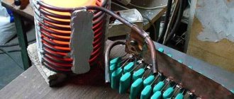
The process of making grinder rollers
Using a circular saw, we cut the multilayer plywood into six rectangular fragments, the long side of which is exactly twice as large as the shorter side.
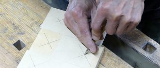
We mark with a pencil using a device for centering square blanks the middle of the halves of rectangular fragments and mark the found centers with a center punch.
We make blind holes for ball bearings on a drilling machine using a Forstner drill.
Then, using a core drill of a larger diameter, we obtain two round disks from each rectangular fragment.
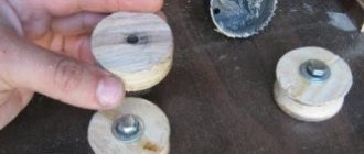
Using a hammer and a piece of multi-layer plywood, we press sealed ball bearings flush into the blind holes.
We make through holes in all disks in the center with a drill with a diameter corresponding to the size of the inner ring of the bearings.
We thread three round disks onto the bolt and washer using glue. We place a wide washer on top and tighten the block with wrenches and leave it until the glue hardens.
Next, unscrew the nut and remove the tightening bolt. Now we have at our disposal three monoblocks with bearings pressed into the outer disks.
Using a pendulum saw, we cut three pieces from a plastic pipe of the required diameter, equal in length to the height of monoblocks of three disks made of multi-layer plywood.
Which is better: heated floors or radiators?
Warm floorBatteries
We grind the side surfaces of the monoblocks, securing them in the chuck of a drilling machine, first with a roughing file, then with sandpaper, to the inner diameter of the pieces of plastic pipe, controlling the turning with a caliper.
Expert opinion
Strebizh Viktor Fedorovich, leading construction foreman
We mark with a pencil using a device for centering square blanks the middle of the halves of rectangular fragments and mark the found centers with a center punch. If you want to clarify something, please contact me!
What other types of machines can be made?
Before creating your own lathe, you should study those varieties that were invented by many interested people. Among the machines, both home-made and factory-made, the following types are distinguished.
Turning and milling
Such a machine is already a powerful modification of previous versions of machines. Most often, a turning and milling machine is equipped with a CNC, because it is extremely difficult to manually control the milling machine with high precision. However, such a machine has a right to exist and is widely used for domestic needs. Its design consists of:
- Beds.
- Electric motor for rotating the headstock.
- A manual milling cutter placed on guides that ensure its movement along the axis of rotation of the workpiece.
With a copier
A lathe and copying machine is necessary when creating a large number of identical products; most often you hear about dishes and balusters for stairs.
There are several options for making a copy lathe: with a router, with a circular saw and with a chisel. All these methods involve the use of patterns. A pattern is a profile of a future product, which is cut from thin plywood.
A handrail is attached along the lathe along the entire length of the workpiece. The pattern is mounted behind the lathe. A cutter or cutter is attached to the handrail, the movements of which are regulated thanks to a stop running from the cutter, cutter or saw to the pattern.
Thus, during the rotation of the block, the cutting tool completely repeats the silhouette of the plywood profile with sufficient accuracy.
Mini
For many household needs, it is not necessary to create a unit of impressive size, capable of rotating a log with a radius of 300 mm. Sometimes a machine with an extremely simple design is sufficient, in which the engine can be a drive from an old tape recorder, powered through a power supply. For the bed of such a machine, you can use a board 150 * 20 and long, which depends only on the needs of the craftsman.
For such a mini-machine, a belt drive would be superfluous, so most often the headstock is mounted directly on the motor shaft. And the head from a drill or a homemade chuck with three clamping screws serves as a faceplate.
The tailstock is made of a block, in the center of which a hole for the shaft is drilled exactly at the height of the motor axis, which can be a dowel-nail. If you provide the machine with a power supply with adjustable output voltage, you can get the unit with a speed controller.
From an electric drill
An electric drill can be found in almost every home. The advantage of a machine driven by an electric drill is that there is no need to buy a separate motor. Drill-powered designs range from the most basic, where the drill is clamped to the table.
On the contrary, the tailstock is mounted using a pair of angles and a nail or a sharpened screw, to a more advanced one, in which the drill serves as a source of rotating force, but is not directly involved in the process of rotating the workpiece. The second method protects the motor from overheating and stalling under overload.
From a washing machine motor
It is a standard layout of a lathe with a motor, direct or belt drive, bed and two headstocks.
When constructing a lathe from a washing machine motor, it is necessary to remember that the motor of a household appliance is designed to circulate with an unbalanced load, but this does not mean that the tailstock can be abandoned. Its presence is mandatory especially when working with long and heavy workpieces. The design of such a lathe is easy to implement at home. To do this you need:
Weld or bolt two steel pipes and attach a motor from a household appliance to one end. Fix a block between the pipes with the ability to move it along the frame; the corner of the tool rest will be attached to it. On the opposite side, the tailstock is installed in accordance with the instructions outlined above.
Collecting videos
The drive roller for the engine is made of plywood. Cut out 10 circles with a diameter of 85 mm. Mark the center and drill a hole with an 8 mm drill. We coat each disc with PVA glue. We collect it in a bag on an M8 stud and compress it from both ends through washers with nuts.
Let it dry overnight for further finishing. Next, drill a hole 24 mm deep. If you don't have a finger cutter, you can use any drill. In our case, the cone from the drill is not a hindrance.
Your motor shaft may be different from the drawing, but this is not a problem. The principle of fastening remains the same, only the dimensions will change, which can be measured with a special tool. Read how to use a caliper here.
After preparing the roller and shaft, you can begin finishing the drive pulley. Attach the motor to the platform, put on the drive pulley, turn on the motor and carefully sand the roller with a flap abrasive wheel.
After cleaning, the edges need to be beveled a little to get a barrel look.
Expert opinion
Strebizh Viktor Fedorovich, leading construction foreman
Often something breaks in it, the body or the anchor, or maybe a new, more powerful and convenient model just comes out, so the old one gathers dust somewhere in a box in the garage. If you want to clarify something, please contact me!
Pulley concept
It is designed to transmit torque from the drive shaft to the driven shaft. To operate such a drive, both shafts are placed in parallel. A flat wheel is put on and secured to each shaft; they are placed in the same plane. The wheels are connected by an endless flexible drive belt. When the drive pulley rotates, the friction force causes the belt to move, covering part of its surface. This motion is transferred to the driven pulley, causing it to rotate.
Belt drives are common among household appliances, mechanisms of low- and medium-power machine tools, and in various internal combustion engines.
It has the following advantages:
- simple device;
- the ability to transmit significant power, modern V-belt pairs transmit up to 400 kW;
- high rotation speed, up to 50 m/s;
- smooth and quiet running;
- damping of vibrations and jerks of the drive shaft during rotation transmission;
- slippage under overloads acts as a safety mechanism.
The pulley itself is a disk on a shaft. It consists of two main parts: the rim and the hub. The rim is the outer part of the part. It engages with the belt and, depending on the type of drive, can be flat or have a recess in the shape of the belt. The side projections above the rim are called cheeks. They keep the belt from slipping. If the drive is wedge, then the cheeks are made inclined; they have an additional function - they increase the engagement area.
If a gear drive is used, then teeth of the appropriate shape are made on the surface of the rim.
If several streams are used in parallel, several grooves are made on the rim.
The hub is the inner part of the pulley. It has a hole for mounting on the shaft. Often the rim and hub are cast, turned, or milled as a single piece.
To reduce the weight of the product, voids are left in the body of the pulley, forming spokes. When made from wood, the presence of knitting needles was determined by the manufacturing technology.
To ensure the interchangeability of pulleys, their standard sizes, technological requirements, and markings are standardized. They are described in GOST 20889-94. “Pulleys for driving V-belts” and in GOST R 50641-94 (ISO 4183-89).
Standard markings include the following parameters:
- number of streams;
- profile of the drive belt used;
- diameter (calculated by cord);
- sleeve designation.
Thus, the marking 8 SPC 500 indicates an eight-lane pulley for an SPC profile with a diameter of 500 mm.
The rules for depicting pulleys in the drawing have also been standardized. The drawing must be constructed so that the product can be manufactured to exactly the same shape and size.
Do-it-yourself grinder: drawings with dimensions and diagrams
- Square pipe 30x30x2 - 250 mm.
- Square pipe 25x25x1.5 - 1250 mm. Taking into account the cut.
- Channel No. 21 – 350 mm.
- Steel strip 50x8 – 700 mm. (With reserve). Or the eyes from the Gazelle spring earrings.
- Old door hinge.
- Sheet 170x190x4 for making a stop.
- Plywood sheet 500x200x8 mm.
- Bearings 201 – 9 pcs.
- Polypropylene couplings for 32 – 6 pcs.
- Polypropylene pipe PN20 – 250 mm.
- M8 hairpin – 1 pc.
- M12 hairpin – 1 pc.
- M8 nuts.
- Spring for tension arm.
- Angle No. 5.0 for mounting the engine to the frame.
- Motor from a washing machine.
Tensioner pulley lever
Making the lever is not difficult, just look at the photo and the assembly drawing, everything immediately becomes clear.
Pay attention to the possibility of adjustment. It will help compensate for possible inaccuracies in the process of welding the lever to the base of the grinder.
Expert opinion
Strebizh Viktor Fedorovich, leading construction foreman
To glue the tape yourself, you will need glue, sandpaper of two adjacent types in terms of grit level, and a piece of fabric. If you want to clarify something, please contact me!
Grinder from a grinder
One of the simplest options for a belt sander is to fix the sander in a wooden or metal structure. For this, an angular base is made. A hole is cut from below for the cable, and the sander is firmly fixed to the vertical wall of the base. All that remains is to make a work table and that’s it, you can start sharpening.
To glue the tape yourself, you will need glue, sandpaper of two “adjacent” types in terms of grit level, and a piece of fabric.
It is necessary to cut coarser sandpaper into strips of the required length and width. Then peel off the abrasive layer on both sides by 2-3 cm. Glue a piece of fabric to the cleaned edges with glue and let it dry. We cut out a “patch” from finer sandpaper and glue it to the fabric.
How to make rollers for a grinder – Manual Workshop
Pay attention to the possibility of adjustment. It will help compensate for possible inaccuracies in the process of welding the lever to the base of the grinder.
Expert opinion
Strebizh Viktor Fedorovich, leading construction foreman
When assembling the grinder yourself, it is important to position the rollers strictly perpendicular to each other to avoid distortions of the belt, which can lead to its breaks. If you want to clarify something, please contact me!
Grinders from Chapai
Currently, a large number of designs of belt grinding tools are offered in the literature and on the Internet. Some of them are considered more successful, others are difficult to implement.
The designs of grinders from Chapai are recognized as one of the successful developments. Developer Andrey Chapai offers professional tools and versions for the home workshop. One of the significant advantages of these models is the wide range of machining angles. To solve this problem, the author proposed an original design of a rotary table. This design formed the basis of all grinders in the professional line. These include: GC 10, GC 12 and GC 16. They received a fairly high rating among specialists. To expand the functionality, the author equipped his products with a device for mounting a disk. A rotating frame assembled from two metal sheets 12 millimeters thick ensures high reliability of the entire tool.
In addition to professional versions, Chapai has developed mobile versions (GCh610-63 and GCh610-71). They are easy to use and demonstrate good consumer characteristics.
Do-it-yourself grinder at home: how to make it
- Think over the design of the device and make drawings. Based on the design features of your model, it will become clear what is required for assembly. I am working on the design; it is advisable to provide for the possibility of grinding parts in both vertical and horizontal directions.
- Prepare hand-held power tools: jigsaw, shmu, drill.
- Arrange with a turner to turn individual parts. Or the lathe itself.
How to glue grinder tape with your own hands and special requirements for it
When developing a homemade grinder with your own hands, it is better to use a standard size sandpaper belt. Standard sizes are lengths of 1830, 1600, 1230, 915 and 610 mm and widths of 100 and 50 mm. Then you won’t have to rack your brains on how to make a grinder ribbon with your own hands. The tape, homemade or factory-made, must meet the following requirements:
- elastic fabric base;
- high ability to withstand angular speeds;
- abrasive resistance;
- possibility of extension without breaking the integrity by 10-15%;
- minimal heating during long-term operation.
Advice! Do not use tapes longer than 1230 mm for your homemade tool; for them you will have to increase the dimensions of the structure, and this puts forward additional requirements for its placement.
When making the tape yourself, try not to make more than one joint. All gluing points are stretched during the grinding process and the tape weakens
- Cut a strip of sandpaper to the desired length and width. Cut the edges of the tape diagonally.
- Connect the edges and pre-glue them on the abrasive side with masking tape.
- Secure the cut with a few drops of superglue.
- Apply glue to the cut area and a piece of silk ribbon, press the surfaces together.
- Wrap the glued area with paper and secure it with a press overnight.
Before using the belt on the belt sander, let it hang slightly under a light load.
Expert opinion
Strebizh Viktor Fedorovich, leading construction foreman
We mark with a pencil using a device for centering square blanks the middle of the halves of rectangular fragments and mark the found centers with a center punch. If you want to clarify something, please contact me!
Types of pulleys
Over thousands of years of use, designers have developed many designs of belt pulleys. Their classification is carried out according to various criteria.
Depending on the type of belt used, there are:
Wedge-shaped
The most common type of product. Used with V-belts. The side cheeks provide additional engagement area, increasing the transmission capabilities of torque and rotation speed.
The inclination of the groove must be indicated on the part drawing.
In order to reduce the dimensions of the transmission or increase its power, several streams are launched in parallel. Such pulleys are called multi-grooved; they have the appropriate number of grooves. Sometimes a single belt with several wedge-shaped protrusions is put on such a pulley. This is a poly-V transmission.
In the drawing it is permissible to give a detailed image of one groove and indicate their number. Detailing of the rest in the drawing is not required
If the permissible load is exceeded in an emergency, slipping begins, protecting the equipment from damage.
V-belt transmissions allow you to transmit the highest torque.
Serrated
There are toothed projections on the inner surface of the belt; teeth corresponding to their pitch are also made on the surface of the rim. Gear-belt pairs do not slip and can transmit more torque. They are also distinguished by the accuracy of transmitting the angular position of the shaft, therefore they are used in gas distribution mechanisms of internal combustion engines. The downside is the lack of a protective function against overloads. The rim is made by milling. There is also production by the rolling method. The detail drawing must indicate the exact parameters of the tooth, its pitch, height, and profile.
Flat-shaft
A classic design used in the very first gears. Absorbs vibration and dynamic loads from the drive shaft. They are characterized by low noise, limited torque and rotation speed.
Using additional rollers, you can connect driven and drive shafts that are in different planes, not coaxial, and change the direction of rotation. In this way, cardan and worm gears can be replaced. The drawing of such a product is the simplest, but it should indicate the radii of the rim and cheeks, if provided. Sometimes cheeks are not provided, and the rim profile is made convex. In this case, its radius should be indicated on the drawing.
Round belt
The groove in the rim has a semicircular profile. Such belt drives are used for low transmitted torques and rotational speeds. They also allow you to change the direction of rotation and connect axes located in different planes. In the drawings of such parts, only the radius of the groove is indicated.
CVT
These are the most complex devices in design. The rim is made in the form of a cone with a conical moving cheek. The V-belt ring has the ability to move along the cone in the axial direction, from a smaller radius to a larger one. The second pulley has a reverse taper, and the drive on it moves from a smaller radius to a larger one. In this case, the transmission ratio changes. The cheeks of both pulleys can move in the opposite direction, changing the gear ratio in the opposite direction.
The advantage of the design is that the gear ratio can be changed without stopping rotation and without removing the load from the drive. It can be difficult to understand the operating principle of a device from a drawing. Three-dimensional modeling allows you to supplement models with kinematic simulations that clearly demonstrate the interaction of mechanism parts.
Source
The process of making grinder rollers
Using a circular saw, we cut the multilayer plywood into six rectangular fragments, the long side of which is exactly twice as large as the shorter side.
We mark with a pencil using a device for centering square blanks the middle of the halves of rectangular fragments and mark the found centers with a center punch.
We make blind holes for ball bearings on a drilling machine using a Forstner drill.
Then, using a core drill of a larger diameter, we obtain two round disks from each rectangular fragment.
Using a hammer and a piece of multi-layer plywood, we press sealed ball bearings flush into the blind holes.
We make through holes in all disks in the center with a drill with a diameter corresponding to the size of the inner ring of the bearings.
We thread three round disks onto the bolt and washer using glue. We place a wide washer on top and tighten the block with wrenches and leave it until the glue hardens.
Next, unscrew the nut and remove the tightening bolt. Now we have at our disposal three monoblocks with bearings pressed into the outer disks.
Using a pendulum saw, we cut three pieces from a plastic pipe of the required diameter, equal in length to the height of monoblocks of three disks made of multi-layer plywood.
We grind the side surfaces of the monoblocks, securing them in the chuck of a drilling machine, first with a roughing file, then with sandpaper, to the inner diameter of the pieces of plastic pipe, controlling the turning with a caliper.
Expert opinion
Strebizh Viktor Fedorovich, leading construction foreman
We will carry out the work using the following tools and devices: a circular, circular and jigsaw, a drilling and lathe, a file and sandpaper, a hammer and wrenches, a device for centering squares, etc. If you want to clarify something, please contact me !
General design and structure of a homemade unit
When designing a homemade lathe for turning, you can consider two design options: with an electric drive and without an electric motor. Despite the antiquity of the method of processing wood using human muscles, this option has the right to exist in conditions where it is necessary to process wood, but there is no possibility of using electricity.
The main structural elements of a lathe are listed below.
bed
The bed is the frame of the entire mechanism. The safety of the craftsman and the quality of the future product depend on the reliability of the frame.
Drive: motor rotor or pedal for foot drive.
Headstock
The headstock is a chuck for clamping the product and its subsequent rotation. Rotation from the engine is transmitted to it through a gear transmission, pulleys or a belt. At the end of the headstock there is a spindle with a faceplate for fixing the product.
Tailstock
The tailstock is needed for additional fixation of the workpiece, which will help improve the accuracy of the rotation axis and avoid unnecessary vibrations. It is a freely rotating blade that can be moved along the axis of rotation of the product to adjust the distance between the headstocks.
Podruchnik
A tool rest is necessary to support the chisel while processing wood. Without a stand for a hand tool, it is impossible to maintain high accuracy of the blade tip hitting the sketch lines and it is extremely difficult to regulate the pressing force of the cutter.