Classification of copy milling machines
Based on the degree of automation, there are three groups of wood copying and milling machines:
- manual (desktop):
- stationary;
- automatic.
On devices of the first group, the workpiece is fixed mechanically. The design of milling machines of the second and third categories provides for the presence of pneumatic clamps that hold the product. This allows you to work with aluminum.
Types of milling machines
Classic machine design
The machines are equipped with a sophisticated design system. These include CNC models that operate in an automated mode. Such devices are obtained by using drawings and a copying device. The classic design consists of five nodes:
- The main element is a metal frame; individual parts are connected by welding. The bed has different heights, so when creating a homemade machine, this particular parameter is selected.
- The front and tailstock are needed to store the box, drive and electric motor. The rear one fixes the workpiece to obtain dimensional parts.
- An electric motor and drive rotate the workpiece.
- A tool rest is needed for the best quality work. The cut site is protected to prevent injury.
- The master and slave centers secure the part.
A homemade lathe-copier for wood makes it possible to carry out high-quality cutting of workpieces no worse than production models.
How the device works
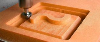
Copy-milling machines for wood are designed for processing flat and three-dimensional parts. With the help of such devices, ornaments and inscriptions, shaped profiles, and complex patterns on workpieces with edges in different planes are created.
There are models of CNC milling machines that process curved parts by copying a template. Thanks to the use of these devices, it became possible to create a large number of parts of complex shapes and the same size.
CNC copy milling machine
Such machines are used primarily in furniture production to create decorative elements of complex shapes.
In addition to furniture, decorative items, architectural elements (bas-reliefs, friezes), souvenirs, wooden weapon parts, and handles of garden tools are created on milling machines. Since all these products differ in shape and size, to create each of them, milling machines of a certain design are required. But regardless of the layout, all devices operate on the same principle.
To work with wood, a milling cutter is installed on the machine - a cutting tool. Product processing is carried out according to the following scheme:
- Using a copier, a contour or surface is defined. A flat template, a reference sample, a spatial model, a drawing, or a photocell can act as a copier.
- The tracking device is connected to the cutting head through a mechanical (less often hydraulic or pneumatic) feed system.
- According to a given template, the cutter creates a contour or surface.
Operating principle of a copy milling machine
Personal assembly of equipment at home
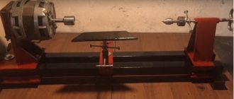
Lathe
Do-it-yourself woodworking machine
In order to assemble a small copying machine for wood with your own hands, you will need to make some effort and patience, as well as invest financially (about 7-7.5 thousand rubles). But this is several times less than the costs that await you if you purchase a ready-made option.
In order to make a copier for a wood lathe, you will need the following components that will be necessary in the manufacturing process:
- electric motor with a power of approximately 800W;
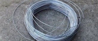
- metal shaft with a nozzle for changing the saw blade;
- metal profile of square section, metal corners;
- wooden sheet;
- furniture guides;
- metal marker;
- fastening materials.
- welding machine, grinder.
First you need to make metal guides.
They will allow you to move the entire copier structure in the longitudinal plane. In this case, two metal corners are used, which are turned over with the sharp side down. The corners are welded together into pieces of metal profile.
This approach allows us to provide the necessary mechanical strength and eliminate the possibility of the guides bending under the weight of the copier. In practice, any other metal profile can be suitable for the manufacture of longitudinal guides, the main thing is that its mechanical parameters allow it to carry out the assigned tasks.
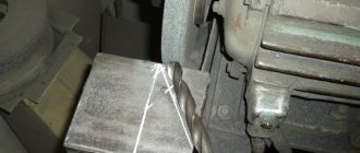
In this case, a wooden box and board were used to make the base of the future copier. The board is sized to allow movement inside the box in a perpendicular plane.
For fastening and subsequent movement, ordinary furniture guides are used.
The engine is attached to the board on top. In this case, the power of the electric motor is 800 W and the speed is 3000 rpm. Depending on your needs, you can use a motor with other parameters.
Next, the shaft should be secured to the board at such a distance that the belt drive normally connects two pulleys, one of which is located at the end of the motor shaft, and the second on the horse shafts of the saw blade. A homemade shaft with one bearing is used here.
A U-shaped structure must be made from a square metal profile. In the upper part of the U-shaped structure, a special metal holder of square cross-section is welded to the horizontal bar. The length of the holder must be less than the length of the marker.
To secure the marker in the holder, holes are drilled on the top plate. A metal nut is welded onto each hole and a bolt is screwed into it. Two bolts will be enough for reliable fixation. The adjustable marker is very convenient when changing saw blades of different diameters.
Simply install the desired disk and use a plumb line to align the marker with the edge of the disk. The marker mount must correspond to the position of the saw blade in all planes. This allows you to simply move the marker along the prepared template to coaxially move the disk along the rotating workpiece.
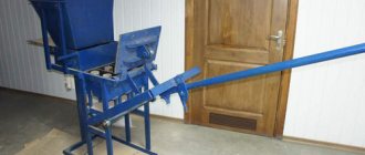
The entire machine is assembled from two channels and metal corners for the sheath. On which a motor is mounted that rotates a wooden piece. In this case, an electric motor with a power of 1200 W is used.
You can use an old frame from some other machine as a frame. For ease of operation, it is better to place the engine on a removable metal plate, which allows you to move the structure with the workpiece, both in the vertical and horizontal planes.
The clamping head is made of four metal plates in the shape of a rectangular parallelepiped. Two nuts are welded into the end walls of the clamping head, into which a metal screw is screwed. A cone with a cartridge is installed at the end of the screw.
In cases where you need to eliminate the possibility of contamination of the surrounding space with sawdust from the operation of the machine or to minimize the percentage of contamination, you should make a hood.
The saw blade is covered with a metal casing, to which a flexible corrugated hose and a compressor unit are connected to create an air flow of a given power.
Video: making a copier for a wood lathe.
Milling options
Milling on a copying machine can be carried out using one of two methods:
- Up milling , in which the part is fed in the opposite direction from the cutter.
- Climb milling , in which both the workpiece and the cutter move in the same direction.
Milling methods
The cutter on such devices can be made of mineral ceramics, synthetic or super-hard material and can replace the grinding procedure. But for machines working with wood products, this is not very important, since this material is not particularly hard.
Wood cutting machine Proma DSL-1200
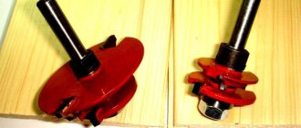
The model in question is intended for processing wooden products that can be used as decorative elements. Experts call a distinctive feature of the design the presence of two incisors:
- The first is designed for processing cylindrical workpieces; more than 10 mm can be removed in one pass. Using the first cutter, you can get a round workpiece, just like on a conventional lathe.
- The second cutter is designed for copier work. It is this that allows you to produce various products using a copier.
This machine model can be used to work with large workpieces. To do this, the structure is equipped with a steady rest, which is mounted on rods that act as guides. The installed faceplate allows processing multi-faceted products.
Main characteristics of the model:
- The installed electric motor operates from a three-phase network with a voltage of 380 V. That is why the machine is not purchased for installation in a private workshop.
- The maximum length of the workpiece is 1200 mm.
- The layout is represented by a combination of two columns, between which the workpiece is placed. Note that the machine has a compact size, due to which it does not take up much space in the workshop.
The disadvantage of this proposal, like many others, is the rather high cost.
The process of creating a machine with your own hands
Drawings of a homemade mini wood milling machine
Buying a copy-milling machine for wood, especially one equipped with CNC, is beneficial for large manufacturers; in other cases, it is easier to create it yourself.
Before manufacturing a machine, it is necessary to create a drawing and decide how the device will be used. If you plan to work with large products, then the size of the machine should also be large so that the cutter produces less vibration. In addition, you need to select an electric motor of sufficient power. The choice depends on the density of the material you plan to work with.
The number of axes is also determined at the layout stage, since changing the design of a finished machine can be problematic. To work with flat parts, two axes are sufficient: with longitudinal and transverse movement. Workpieces with slight relief also require a perpendicularly moving axis. For more complex products, four or five axes may be needed.
There are many milling machine designs, but they all consist of three elements:
Copy milling machine - device
- working surface;
- bed;
- milling head.
The design of the working surface of the copying machine must provide for height adjustment, and the milling head must be high-speed and equipped with an electric drive.
The layout of a wood copy-milling machine can be vertical or horizontal. The comfort of working with the tool and unloading finished parts depends on this.
Pantograph
Homemade pantograph - drawing
The cheapest option, for the manufacture of which you need several boards and a router. Designed for flat threads.
The shape resembles a parallelogram. Thanks to this design, when moving, nodal points describe equidistant curves. To scale the device, the link is lengthened.
The side of the parallelogram is half as long as the total length with the copying tip. Because of this feature, when copying any part with the tip, the cutter will halve it, which reduces the copier error.
Model with plane-parallel mechanism
Used for contour milling. Unlike the previous model, a curved trajectory is achieved by adding two axes perpendicular to each other. The third axis inserts the cutter into the workpiece.
To balance the system, the design includes a counterweight on the other side of the swing frame. To be able to adjust, it is better to place it on a threaded rod.
Copy milling machine with plane-parallel mechanism
Model for volumetric milling
On such a device, the milling head is placed on a swinging frame, which during processing moves on roller carriages along perpendicular guides. The model and the part are mounted on two rotating units at the bottom of the base. The open frame makes it easy to clean out sawdust.
Copy milling machine for volumetric milling
Duplicarver-2
Serial copy-milling machine for wood, designed for both flat-relief and sculptural carving. The design provides five controlled axes:
- side arms;
- rotating frame;
- milling head;
- work tables;
- lateral movement of the head.
Quite light (weight about 28 kg) for one person.
Duplicarver-2
Duplicarver-3
The design of this model is similar to Duplicarver-2, but has two additional rolling pin guides (another linear axis), and the rotary tables are installed vertically. Thanks to such changes, it became possible to work with long volumetric threads.
Other functional parts
Their list is as follows:
- Base plate. Absorbs elasticity waves.
- Drive board for vibration damping.
- Comb stops (combs). Needed to neutralize vertical vibrations of the workpiece.
- Static side stop. Guarantees the correct feeding of the part and the depth of its horizontal processing.
- Dust catcher.
Drive unit
It is better to make the opening for placing the drive round, so the machine will have less vibration during operation. The motor must not come into contact with the plate.
Installation of the drive in this plate is as follows:
It is better to create the drive board from PCB or fiberglass with a density of at least 1.5 cm.
Thick plywood (1.9 cm) treated with a vibration-absorbing agent is used for the slab.
The board and the plate are separated by a gap of 0.5 - 1 mm. It is desirable for the engine to have mounting feet, and they should extend beyond the body. This will allow the cutter to move upward. To install it, long motor bolts are used. The removal of the cutter is ensured as follows: steel washers with rubber gaskets are put on the bolts in turn between the engine housing and the suspension cushion.
Emphasis
Suitable material for the stop is thick plywood (from 2 cm). It is required to drill 3-5 holes for combs and risers. The first two are located 5 mm from the extreme sides of the cutout for the cutter. Others - after 2.5-3 cm. The positions of the stops depend on the parameters and quality of the workpiece.
The side support diagram is as follows:
It can have this configuration:
System elements
- A 15-20 liter bucket with a tight lid and snap-on latches.
- Pipe 1 – inlet. The diameter is 2 cm. Its end is beveled by 45 degrees and rotated by 25 degrees to the outside. It is placed 2 cm from the side of the container.
- Branch pipe-2 – exhaust. Diameter – 3 cm. Placed strictly vertically in the bucket. Its selective ending is narrowed to 1.5-2 cm.
- Vacuum cleaner.
Combs
Oak or walnut is used for combs, without fungi or defects. They are made on the right and left sides for ease of feeding the workpiece.
Drawing:
The length of the first tooth is reduced by 3 mm. The reason is that it acts as a rebound spring for the entire ridge. Without this, damage may occur.
The ridges are attached to the stop using a special bolt through a slotted hole.
The non-working element is fixed with a self-tapping screw to the same stop through hole D7.
To work, the comb is positioned so that it contacts the workpiece with all teeth except the initial one. Then it is secured with a lamb.
Advantages of CNC machines
Despite the fact that a manually operated wood copy-milling machine greatly facilitates work and increases productivity, it still needs to be controlled. But models used in mass production are equipped with computer numerical control (CNC). When working with such a device, a person only needs to load the workpiece and pick up the finished part.
Advantages of CNC machines
A simple milling machine equipped with CNC operates from a control program that is created by the operator in a special system, according to a three-dimensional model developed in advance by a design engineer.
Unlike a simple CNC milling device, copying models have a programming system installed, which itself creates a control program. Such devices have an additional CNC attachment, which probes the reference workpiece, develops its three-dimensional model, on the basis of which a control program is created.
The main problem with numerically controlled machines is their high cost. For small production there is no point in such a device, since the payback period should be no more than five years. At home, with CNC it is easier to make not a copying machine, but a regular milling machine, which, however, is also not the easiest task.
Related video: Do-it-yourself copying machine
Publications on the topic
Description of CNC metal plasma cutting machine
Step-by-step instructions for making a stationary circular saw with your own hands
Options for making a router from a grinder with your own hands
Details
Tabletop for router
To make a manual router from a drill with your own hands, you will first need to understand the table. It will be more convenient to process the ends, as well as milling grooves for joints using the tongue-and-groove method, using a milling table with protruding tools. They have a simple design, and the drawings will be easy to develop yourself. A small bench-type table will also work. The lid should flip over and a hole should be cut in it.
Its size should be approximately 0.5 cm larger than the maximum diameter of the cutter that will be used. A bar will be installed perpendicular to the table, which will be parallel to the side at such a distance that the spindle axis of the attached electric drill will perfectly coincide with the center of the hole. The body of the electric tool should be attached to the bar with stops and clamps; in the normal state of the table, the chuck will be located under the cover, and the cutter inserted into it will protrude. During processing, the wood part will move along the surface of the table and rest against the template, as a result of which milling will occur.
In addition, the tool can be secured in other ways. The main thing is that the center of the hole perfectly coincides with the axis of the cutter, and that the chuck and switch are accessible. All machine elements must be attached rigidly, without any distortions.
The simplest machine
They must be located strictly perpendicular, that is, at an angle of 90 degrees. A hole should be made in the sole for the exit of the tool. The width of the stand will be equal to the dimensions of the body of the electric drill and 2 cm longer. A drill will be attached to it using a clamp located above the chuck. It will additionally be fixed with a stop, which will press the back side of the body on the other side of the spindle, or with another clamp lower than the handle. The gusset will provide rigidity to the structure, with one side adjacent to the sole, and the other to the stand itself.
When cutting out the sole, or rather the base of the structure, you should draw a square on a sheet of plywood, and its sides should be equal to the width of the body of the electric drill. On both sides that are adjacent to it, you need to add strips that are equal to the thickness of the plywood. Mark the center of the tool and make a hole using a slotted or core drill bit.
Next, you should cut the sole along the contour, and the corner opposite the connection of the scarf and the stand should be rounded. On the reverse side, drill a 0.4 cm hole and make recesses that will be hidden under the screw heads using a 0.8 cm drill. Otherwise, the screw heads will again scratch the table when protruding, and also disrupt the fit of the sole. There will be a skew.
You can stick a thin rubber band or even a piece of linoleum on the bottom of the sole. This will ensure smooth sliding while the router is operating. Using a square, set the stand in place and screw it into place. The gusset will be attached with one side to the base, the other to the stand, which will ensure the rigidity of the structure. Afterwards, you need to mark the position of the electric drill when the tool begins to fall lower than the sole. Screw on the stop and clamp, and for ease of work, the sole can be made of organic glass.
Machine with vertical cutter movement
If you have metalworking experience and the required set of parts and components, then you can install a homemade cutter on the side cylindrical racks. Place springs on them from below, which will lift the drill upward. Fastening is carried out using metal corners, screws and staples. The milling depth can be adjusted with stop screws.
Assembly algorithm
Before you start making a hand router based on a conventional electric drill, you need to prepare all the necessary materials and drawings, indicating the dimensions and
how the drill will be attached, which will replace the hand router:
- Mark the center of the spindle axis on the soleplate or table.
- Cut a hole for the outlet of the electric tool.
- Next, place the electric drill on the stand and mark the position of the stop and clamp to secure everything.
- The gusset and stand should be screwed strictly at right angles.
- Secure the tool body to the base.
The machine, which will be made by hand, must be durable and free from distortions and backlashes. In this case, it will be possible to work on it like a regular router.
What is it and what is it for?
The copying sleeve is a ring that slides along the edge of the template. As a result, the cutter exactly follows the specified contour and does not intersect the marking lines. It is impossible to cut a workpiece smoothly by guiding the tool manually, much less make several completely identical parts.
The copy sleeve consists of a ring and a flange. The axis of symmetry of the device coincides with the axis of rotation of the spindle. The flange is made according to the size of the hole in the supporting plane of the router, and is attached to it. When pressure is applied to the housing with the motor, the working part of the tool is lowered along the guides, perpendicular to the supporting sole.
The cutter ends up below the sole and cuts into the workpiece. The copying ring rests its side surface against the end of the template, preventing the tool from going beyond its boundaries. Using a stencil, you can cut out a design of any complexity onto a part. It is enough to go along the contour with a cutter, then clean the entire area of the understatement.
Reference! Only the corners into which the rotating tool does not go are left unprocessed. They have to be removed manually with a chisel.
Copy model CL-1201
To produce wood products, a machine model CL-1201 or CL-1500b can be used. The first version has very attractive performance characteristics:
- The spindle used can change the direction of rotation. Due to this, the scope of application of the model is significantly expanded. Changing the direction of rotation of the spindle is carried out with a special handle.
- The machine allows you to select the spindle rotation speed with high precision. Due to this, it is possible to provide the most favorable conditions for turning wood based on the weight, dimensions and type of wood.
- There is a remote control to set basic parameters. The design can be installed on the headstock or tailstock, depending on the preference of the master. The remote control is represented by a combination of several keys.
- Cast iron is used in the manufacture of the column. In addition, the frame is manufactured using high-quality steel. By combining these materials, the degree of vibration of the structure during operation is reduced.
- The basic delivery includes a copier, which can be used for processing. Due to this, costs are reduced and the machine becomes more functional in use.
- The design of the machine has a milling attachment, which can be used to produce longitudinal grooves.
- The tailstock is used for more precise fixation of the workpiece. Its position may also change. The supply includes centers, which are selected depending on the characteristics of the workpiece.
- The support is characterized by high mobility. The cutting depth of the tool can be adjusted using a lever.
In addition, the manufacturer paid quite a lot of attention to the degree of protection of the machine from environmental influences. For example, the engine has a protection system against overheating or overload, all electronic parts are also protected from moisture and dust.
The only but significant drawback is the high cost of the proposal. A homemade design will cost several times less.