Welding is one of the most commonly used methods of joining metals and alloys. Even masters sometimes make seam defects, not to mention beginners. When carrying out such work at home, visual inspection is sufficient. In production, various methods are used to control the quality of the weld, and one of the most advanced is radiographic testing.
Brief description of the method
Metal parts are connected using different types of welding, which can result in weld defects.
It's connected with:
- violation of work technology;
- foreign bodies entering the welding site;
- insufficient welder qualifications, etc.
All this leads to a deterioration in the quality of the seam and a decrease in its strength.
X-ray inspection (RT) of welded joints is a non-destructive method that allows you to identify hidden defects at an early stage and avoid accidents in the future.
This is a highly accurate method with which you can objectively assess both the nature and size of defects. The technique allows you to monitor the condition of welds on pipelines, tanks, various equipment and metal structures, etc.
Decoding
Interpretation of radiographs is carried out in a shaded room using a negatoscope. It is a device whose purpose is to view radiographic images, including radiographs, through transmission. The negatoscope provides the ability to adjust the brightness of the lighting. If its value is too high, small defects may be missed.
After decoding, a conclusion is drawn up. Before resorting to this method, it is necessary to find out what weld defects are detected using radiographic testing. These include:
- undercuts;
- lack of penetration;
- cracks;
- pores;
- foreign inclusions;
- slags
In addition, it is possible to evaluate the amount of concavity and convexity in places where visual inspection is not possible. Abbreviations are used when writing results. So, “T” means a crack, “N” is a lack of penetration, “P” is a pore, “W” is slag, “V” is the inclusion of tungsten, Pdr is an undercut. The size of the defect is indicated next to the letters. The nature of the distribution is also taken into account.
On this basis, shortcomings are divided into groups:
- Separate.
- Chains . There are more than three defects on one line.
- Clusters . Location of at least three defects in one place.
The size of the defect is indicated in millimeters.
GOST and other requirements
The radiographic method of testing welded joints is regulated by GOST 7512-82. This method allows you to control the weld with a thickness of the welded elements from 1 to 400 mm, and when using powerful equipment - up to 500 mm.
For this purpose, X-ray, bremsstrahlung and gamma radiation are used, and radiographic film is used to obtain an image.
The basic requirements for accessories for such control are as follows:
- Markings comply with GOST 15843-79.
- Radiographic films meet technical specifications.
- The radiation source complies with GOST 20426-82.
- Intensifying screens can be metallic or fluorescent.
- Lightproof cassettes ensure that the screen is pressed tightly against the film.
- The lead screen protects the film from scattered radiation.
- Sensitivity standards can be plate, wire or groove.
Properties and capabilities of X-ray
The peculiarity of radiography is that the permeability of materials depends on the length of the generated rays. In dense materials they are scattered and partially absorbed. The lower the density of the connection being tested, the clearer the image will be.
The ability of some chemical elements to glow for several seconds under the influence of X-ray radiation makes it possible to expose a special film and obtain an image of existing seam defects.
If the material being tested is homogeneous, the result will be a light and monochromatic image. If there are various defects, cavities, voids, it will have darkening.
Some models of flaw detectors use the ability of ionized air to transmit electricity. The higher the degree of ionization, the better the current is conducted. This principle makes it possible to obtain an image not on film, but on the screen of an oscilloscope when performing RC.
In large quantities, X-ray radiation negatively affects the human body, irradiating cells and tissues. Large doses lead to the development of radiation sickness and even death. Therefore, the use of fluoroscopy to control the quality of welds requires strict adherence to safety rules.
Scope of flaw detection
The X-ray method of checking welded joints makes it possible to accurately determine such parameters of existing defects as size, shape and location in space.
It allows you to control the quality of welds at critical facilities, such as main oil, gas, water pipelines, during the construction of structures and equipment for nuclear power plants, in machine, aircraft, shipbuilding, etc.
History of the creation and implementation of the methodology
Initially, the quality of welds on metal structures used in aviation was assessed using radiation flaw detection. Over time, scientists and practitioners accumulated enough knowledge to publish the first manual in 1934, which described in detail the technology of scanning electric arc welding areas with X-rays. In the middle of the 20th century. Thanks to a significant expansion of the development and research bases, the production of X-ray units was put on stream.
By the beginning of the 1960s. To control the quality of welded joints using this technology, standard installations were produced. These were mainly RUP devices, which were developed by . The advantages of these devices:
- X-ray energy range from 50 to 400 kV,
- precise focusing of X-ray tubes,
- radiation severity,
- power.
The development and improvement of technology was influenced by the Soviet scientist A.K. Trapeznikov, as well as his followers - B.V. Borshchev, S.T. Nazarov, O.T. Silchenko, S.V. Chernobrovov.
additional information
Before using the radiographic quality control method, you need to know that its diagnostic range is limited by the sensitivity of the device.
Using a flaw detector it is impossible to detect:
- voids that are 50% smaller than the standard values for the specified device and are located in a direction parallel to the action of the x-ray beam;
- inclusions located in the direction of the beam, the size of which is 2 times less than the sensitivity of the device;
- defects that coincide in the photograph with the edges and sharp corners of the elements being tested.
We recommend reading Reinforcement welding technology
This method detects all other defects quickly, efficiently and with high accuracy.
4.7. Monitoring the correction of defects in welded joints
4.7.1. Control of the completeness and quality of defect removal is carried out in accordance with the PDD for welding.
4.7.2. Corrected sections of seams must be subjected to inspection by all methods provided for by these PCs for this connection.
Table 4.5
Acceptable parameter values and number of defects identified during ultrasonic testing of welded joints
| Category | Nominal thickness (smallest) of connected elements, mm | Maximum permissible equivalent (by notch) defect dimensions, mm ´ mm | Control level of sensitivity for fixed defects | Number of permissible defects on any 100 mm seam, pcs. |
| ND | up to 7 | 2,5´1,5 | 6 dB below the rejection level | 6 |
| St. 7 to 15 | 2,5´2,0 | 7 | ||
| St. 15 to 20 | 3,5´2,0 | 8 | ||
| D | up to 7 | 2,5´1,5 | Same | 7 |
| St. 7 to 15 | 2,5´2,0 | 8 | ||
| St. 15 to 20 | 3,5´2,0 | 9 |
Notes:
1. For metal up to 5 mm thick, assessment standards are given only for monitoring butt welded joints.
2. The conditional length of permissible defects should not exceed the conditional length of the control reflectors.
Table 4.6
Standards for single pores and inclusions acceptable for metallographic studies, mm
| Nominal thickness of welded elements | Allowable largest defect size |
| St. 3.5 to 5.0 | 0.6 |
| St. 5.0 to 6.5 | 0.8 |
| St. 6.5 to 8.5 | 1.0 |
| St. 8.5 to 12 | 1.5 |
| St. 12 to 20 | 2.0 |
| St. 20 to 35 | 2.5 |
4.7.3. If, during quality control, unacceptable defects are again discovered in the corrected area, then repeated correction and control are carried out in the same order, as well as control by penetrant flaw detection.
4.7.4. Areas of welds subjected to repair must be indicated in the reporting documentation for welding work.
- To the begining
- Back
- 2
- Forward
- In the end
Equipment design features
Nowadays, radiographic testing, related to digital flaw detection, is more often used. The resulting radiation image is converted into a digital image and the information is displayed on the screen.
The detector for monitoring x-rays or gamma radiation that passes through the object being tested is a photodiode with a scintillator, which is susceptible to radiation and emits a visible spectrum of light that is in direct proportion to quantum energy.
Such radiation produces a current inside the photodiode, the radiation is converted into electricity and then displayed on the screen.
The detector units are moved relative to the object being tested and receive a continuous stream of information, which is recorded in the computer memory for further detailed testing. To quickly assess the quality of the connection, the resulting image is immediately displayed on the screen.
Gamma ray flaw detectors
They provide a given frequency of gamma radiation intensity fluctuations. As a result of changes in radiation intensity, transverse stripes are created in the image.
The existing radiation intensity deviations are higher than the statistical noise values. Modern technology, equipped with advanced software, makes it possible to reduce these fluctuations. Such X-ray machines are conditionally applicable for performing RK welds.
X-ray device
These devices have a constant potential and high-frequency fluctuations, random in time. They provide a deviation in gamma radiation intensity of more than 1%. In this regard, the use of these devices when performing radiometric monitoring is not recommended.
For X-ray inspection it is necessary to use equipment that has the following indicators:
- radiation stability – more than 0.5%;
- fluctuation frequency – not higher than 0.1 Hz.
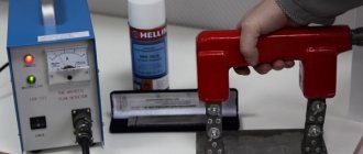
Equipment for flaw detection of welds
This flaw detection technique uses several types of X-ray equipment. Their design includes:
- X-ray tube placed in a protective housing;
- a high voltage generator, which includes a pair of transformers and a rectifier;
- control panel consisting of a signal installation, measuring sensors, current and voltage regulator, transformer.
Depending on the principle of operation, X-ray devices used in flaw detection of welds are divided into pulsed devices and devices with a constant load. The pulse equipment includes X-ray and control units. Equipment with constant load are divided into:
- monoblocks,
- cable devices.
A monoblock is a device whose main element is a transformer unit consisting of a high voltage transformer and an X-ray tube. Typically, these devices are lightweight and compact. They are used when maneuverability is needed and when the emitter is more than 30 m away from the control panel.
Cable X-ray machines are equipped with an autonomous generator, an X-ray tube and a control panel. They are usually mobile, so they are used mainly in laboratories and workshops.
Operating principle of radiographic testing installations
The main part of the device used for radiographic monitoring of the condition of the seam is the emitter. It serves to create rays and emit them.
The emitter is made in the form of a vacuum vessel, which contains the anode, cathode and filament. During the acceleration that charged particles develop, X-rays are generated that illuminate the product under study.
The electrical potential created between the cathode and anode accelerates the electrons released by the cathode. These initial rays are still not enough for the device to operate.
When colliding with the anode, the rays are slowed down, which leads to their stronger generation. Their collision with the anode leads to the formation of electrons on it. As a result, rays are formed and sufficient radiation is generated.
The emerging rays move in the direction of the quality control location. Where the metal is dense, they are almost completely absorbed, and in places of defects they pass further.
The transmitted rays on the film form an image, the contrast of which depends on the number of rays passing through the seam. The more defects there are, the clearer this place appears in the picture. This way their location and size are determined.
What are the requirements?
When performing radiographic testing, any existing X-ray equipment can be used. Manufacturers rarely indicate in the characteristics data on fluctuations in the radiation intensity of the device, because this value is not critical.
Since radiometry ensures the collection of information online, the following requirements are imposed on the X-ray machines used:
- The density of the gamma flux passing through the object under study must be sufficient to provide enough time to record the thickness of the part along the scanned area.
- The gamma radiation intensity must be constant.
To ensure high-quality radiometric monitoring, a highly stable radiation source is used, guaranteeing maximum beam flux density and energy spectrum.
Safety at work
Although the equipment used for radiographic testing emits small doses of radiation, the following safety rules should not be neglected:
- The device must be shielded so as not to release rays beyond the area in which the control is carried out. Screens must be installed in the walls of the room in which such research is carried out so that radiation does not spread to people working in neighboring workshops.
- You should spend a minimum of time near a working device. If checking the quality of a seam is carried out on the street, then it is better to move away from it. If the device is located indoors, then during its operation you need to be near it for a minimum of time.
- The operator of radiographic equipment must wear personal protective equipment. There should be no strangers nearby while the equipment is operating.
- Before using the device, you need to check its functionality and the correctness of the settings. Most often, emergency situations occur due to incorrect settings or equipment malfunction.
- It is necessary to control that the resulting radiation has time to be eliminated from the body. The radiation dose can be determined using a dosimeter. The small doses of radiation received have a cumulative effect.
- It is especially important to control the level of air ionization in a closed laboratory. Radiation causes the air to ionize, resulting in the creation of electricity.
We recommend reading Silumin: composition, properties, application of the alloy
Identification of defects
The presence of the following defects in the weld seam is unacceptable:
- Cracks (cold and hot). Before the seam hardens, hot cracks may appear, and after it has completely hardened, cold cracks may appear. They are often invisible during external inspection of the seam.
- Por. This defect is the most common during welding work. In most cases, its appearance is associated with improperly or insufficiently prepared surfaces to be joined, the presence of drafts, etc.
- Slags and other foreign bodies.
- Burn-through. It occurs when the welder is insufficiently qualified or the equipment parameters are incorrectly selected. It appears in the form of through holes in the seam.
- Undercut. A defect in the form of a groove located in the part being welded along the weld seam.
- Influx. During operation, filler material flows onto the base metal, but does not form reliable fusion with it.
- Lack of cooking. An incorrectly selected mode of work, i.e. low current, does not allow the parts to be connected to be fully and efficiently welded.
- Loose areas. They are characterized by a fragile seam structure.
Requirements for images and features of their decoding:
- Only well-dried photographs are decrypted. They should be free from scratches, fingerprints, etc.
- Decoding is performed in a darkened room using negatoscopes.
- The results obtained are recorded in a special journal, and the conclusion is sent to the technical control department.
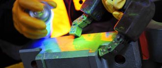
Visual inspection
Using an external examination, you can identify not only visible seam defects, but also invisible ones. For example, the unevenness of the seam in height and width indicates that there were interruptions in the arc during the welding process. And this is a guarantee that the seam inside has lack of penetration.
How to properly conduct an inspection.
- The seam is cleaned of scale, slag and drops of metal.
- Then it is treated with technical alcohol.
- After another treatment with a ten percent solution of nitric acid. It's called etching.
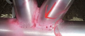
- The surface of the seam is clean and matte. The smallest cracks and pores are clearly visible on it.
Attention! Nitric acid is a material that corrodes metal. Therefore, after inspection, the metal weld must be treated with alcohol.
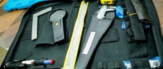
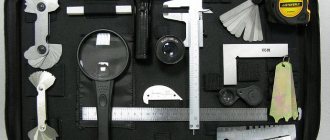
The magnifying glass has already been mentioned. Using this tool you can detect tiny flaws in the form of thin cracks less than a hair thick, burns, small cuts and others. In addition, using a magnifying glass you can check whether the crack is growing or not.
During inspection, you can also use calipers, templates, and a ruler. They measure the height and width of the seam, its even longitudinal location.
Advantages and disadvantages of the method
This method of quality control of welding seams is highly effective, because has the following advantages:
- To get an idea of the condition of a seam made by any welding method, just a few seconds are enough.
- RK has higher accuracy compared to other non-destructive testing methods.
- RK detects a wide range of defects.
- Radiography shows not only the location of the defect, but also its size and type.
- The method can be used in the field, which is convenient when monitoring pipelines or inspecting construction sites.
The radiographic testing method also has its disadvantages:
- X-rays require special equipment and are expensive.
- It is necessary to use disposable consumables: film or plates, as well as reagents, screens, etc.
- To perform work, the operator must undergo training and pass exams.
- To get a reliable result, you need to configure the equipment correctly.
- The radiation from the device is hazardous to health.
Safety
For all its advantages, the method is potentially hazardous to health. Therefore, it is necessary to shield the device. The controller should not be unnecessarily in the irradiation area. Access there to unauthorized persons should be prohibited. To do this, warning signs should be posted.
When working indoors, its walls must be covered with shielding plates. The controller must be provided with a set of protective clothing. Before starting the process, it is necessary to check the serviceability of the equipment.
X-ray inspection technology
Before applying this technology, be sure to clean the surface. The quality of the settings greatly affects the accuracy of the results obtained.
Radiographic testing sequence:
- Installation of the device. On one side of the area being tested there should be an emitter, and on the other, a flaw detector sensor.
- Turning on the device. At this time, a beam of rays passes through the seam and enters the sensor. The equipment can operate from a battery or from the mains.
- Transmission of the received signal by the sensor to film or screen. This depends on the model of the device used.
- Recording a digital analog signal to a storage device.
- Deciphering the information received and recording existing defects in the relevant documentation.
For welds
For classic seams, the procedure for monitoring their quality using X-ray control includes the following steps:
- removal of slag, scale, and any contaminants from the weld being examined;
- marking and marking of the joint (a marking and a sensitivity standard are installed on each);
- choice of work plan;
- setting control parameters;
- direct transillumination;
- film processing;
- decoding the results;
- recording the received information in documentation.
For pipelines
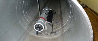
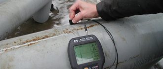
This method is actively used to control the seams of pipes of different diameters. It is often necessary to conduct research far from populated areas where it is impossible to deliver the installation.
In this case, compact devices – crawlers – are used. They move independently inside the pipe and are controlled remotely. The devices are designed to work in pipes with a diameter greater than 325 mm.
It does not matter where the object being studied is located - above, underground or under water. Climatic conditions do not matter, so it can be used in any region and at any time of the year.
On command, the device stops and takes radiographs or panoramic photographs.
We recommend reading: How to make a potbelly stove for your garage yourself
For tanks
During acceptance of tanks, visual inspection of welded joints is first carried out and only then radiographic inspection. At the intersection of seams, films must be placed in an X- or T-shaped direction.
The length of the image must be at least 240 mm, and the width must correspond to the standard one. Check the butt seams on the walls of the tank, the bottom, as well as at the places where they meet.
If unacceptable defects are detected in this area, an additional photograph is taken. To check seams on tanks, flaw detectors of at least level 4 are used, and the results are interpreted by specialists of at least level II.
For different types of connections
Radiographic testing of different types of welds is carried out in accordance with GOST 7512, OST 26-11-03, OST 26-11-10. Before carrying out work, take into account the characteristics of the metal and the weld being tested. Fillet welds are checked according to GOST 26-2079.
Using this method, the quality of corner, T and butt joints, intersections of seams, etc. is controlled.
By type of metal
Using X-ray scanning, you can check the quality of welds and the main product made of different metals. The hardware settings will be different, because... The transmission of rays through different materials differs.
The quality of control depends on the correct settings.
Modern equipment allows not only to identify the type, size and location of defects, but also to decipher the results obtained automatically.
Sample manipulation (oblique sample inspection)
Plumbing in a private home: step-by-step description of the installation process
This ability to rotate the sample (printed circuit board) during fluoroscopic examination allows you to display the shape, size and placement of defects from various viewing angles
This is especially important for double-sided boards where top and bottom components may obscure the inspection area of interest. Also, this function makes it possible to more accurately determine defects in electrical connections for microcircuits (BGA, QFP, QFN, etc.)
NOTE
: A tilt angle of 0 to 40° is ideal for this application. Manual or mechanical rotation will affect equipment cost and operator comfort, and have slight differences in efficiency.
Using filmless devices
Now, increasingly, instead of detectors that use film, devices are used where the radiation is immediately processed into digital form and displayed on a screen.
“Filmless” radiography is divided into the following types:
- Digital. X-rays are converted into electric current, the magnitude of which depends on the strength of the radiation. First, the rays hit the scintillator layer, where they turn into light photons. They penetrate the photovoltaic matrix located at the rear and activate a charge in it, which is read and appears as an image on the screen.
- Computer. The mechanism of photostimulated luminescence is used here. Some of the crystals store the absorbed energy, and after optical or thermal stimulation, the stored energy begins to glow. Barium fluorobromide is most often used as a phosphor. The more energy that hits the storage platter, the more visible light there will be in the image. To obtain a new image, the remaining glow on the screen is erased using a powerful beam of light, and the equipment can be used again.
Advantages of “filmless” radiography:
- the need to carry out “wet” processing of the resulting images;
- shorter exposure time;
- the ability to study parts with different radiation thicknesses.
Physical foundations of methods and technology of radiation flaw detection.
Radiation non-destructive testing is based on the use of the penetrating properties of ionizing radiation and is one of the most effective and widespread types of testing. In the oil and gas industry it is used primarily for monitoring welded joints of main and field pipelines, tanks for storing oil and petroleum products, pressure vessels and other objects. The implementation of this type of control involves the use of at least three main elements: a source of ionizing radiation; object of control; a detector that records the results of the interaction of ionizing radiation with the test object.
In radiation non-destructive testing, three types of ionizing radiation are used: bremsstrahlung, gamma and neutron.
Control using neutron radiation is carried out only in stationary conditions. The main sources of neutron radiation are particle accelerators, nuclear reactors and radioactive neutron sources. In field conditions, during the operation or construction of a facility, x- or γ-radiation is usually used. The sources of x-radiation are portable pulsed X-ray machines, and the sources of γ-radiation are radioactive sources. With their help, you can shine through steel products with a thickness of 1…200 mm.
The control and measuring part is a group of instruments that are used to measure and regulate time, current, voltage and frequency. The high voltage applied to the electrodes of the X-ray tube is 100...400 kV. As the voltage increases, the radiation maximum shifts toward shorter waves, and the penetrating power of the radiation increases.
The X-ray emitter, in addition to the X-ray tube, includes a protective casing filled with an insulating medium - transformer oil or gas under pressure, as well as a collimator - a device designed to form a beam of directed radiation.
Radioactive sources of γ-radiation are used in gamma flaw detection and are supplied in ampoules transported in special containers. The isotopes Co60, Se75, and Ir192 are usually used as radioactive sources. The emergence of such relatively cheap radioactive sources led to the creation of special sets of equipment called gamma flaw detectors. There are gamma flaw detectors for frontal and panoramic scanning, as well as universal hose gamma flaw detectors. Gamma flaw detectors of the first type are only a emitting radiation head, installed in the control zone and equipped with a mechanism for opening and closing the shutter. The most widely used are universal hose-type devices, consisting of a radiation head, a hose-ampoule line, a control panel with a mechanism for moving an ampoule with a radioactive source along the ampoule line, and a collimating nozzle. In these devices, an ampoule of a radioactive radiation source from the radiation head is fed through an ampoule line using a flexible cable driven from a manual or electric remote control. The presence of a remote drive makes it possible to minimize the operator's radiation exposure by removing him from the radiation source by 12 m or more.
Unlike X-ray devices, gamma flaw detectors can be operated without energy sources, which is especially important in field conditions. They are also often used to control closed objects of complex shape, when it is impossible to install X-ray emitters. The disadvantages of gamma flaw detectors are: the need to periodically replace radiation sources that have lost activity, limited capabilities for regulating operating modes, as well as the lower contrast of radiographic images compared to X-ray ones.
Ionizing radiation in general, from the point of view of its impact on the human body, is the most dangerous among those used in non-destructive testing, therefore all equipment used in radiation monitoring is subject to mandatory certification and periodic re-certification. Specially trained and certified personnel are allowed to work and are subject to mandatory radiation monitoring.
Among the radiation methods, transmitted radiation methods are used to detect and measure internal defects in a product. When passing through a controlled product, ionizing radiation is attenuated due to its absorption and scattering in the material of the product. The degree of weakening depends on the thickness of the product, the chemical composition and structure of the material, the presence of gas cavities, sulfide rolls and other foreign inclusions in it. As a result of the passage of ionizing radiation through the controlled product, the detector records the intensity distribution of the radiation flux that has reached it, called the radiation image of the product. The presence and characteristics of defects are determined by the density of the resulting radiation image. The uniform intensity of the radiation reaching the detector indicates the absence of defects. A decrease in the density of the radiation image corresponds to an increase in the thickness of the controlled product, for example, in the area of welds or splashes (droplets) of metal from welding. In turn, an increase in density corresponds to areas of products with a lower radiation thickness that have defects. Scheme of radiation monitoring using the transmitted radiation method.
1 - radiation source;
2 - object of control;
3 - defect;
4 — detector (film cassette);
5 - trace of a defect.
The intensity of radiation reaching an object depends on the initial flux at the radiation exit point, the distance a to the object and the characteristics of the radiation itself:
,
where R and b are constants determined by the nature of the radiation.
After passing the object, the intensity of the radiation incident on the detector is determined from the expression
,
where μ is the coefficient of attenuation of radiation by the object material; δ—object thickness; B is the so-called accumulation factor, determined experimentally (with a narrow beam of rays B = 1).
Due to the exponential dependence of the attenuation of the intensity of ionizing radiation, the sensitivity of monitoring sharply decreases with increasing radiation thickness, therefore the maximum depth of monitoring is limited and for portable devices usually does not exceed 200 mm, which is one of the disadvantages of the radiation monitoring method.
In addition, a very significant drawback is that cracks whose radiation thickness is less than a given sensitivity class are not detected using the radiation monitoring method. This primarily applies to cracks oriented perpendicularly or at a small angle to the direction of ionizing radiation.
Methods of radiation monitoring by transmitted radiation differ in the methods of detecting the results of the interaction of radiation with the test object and, accordingly, are divided into radiographic, radioscopic and radiometric.
The radiographic method of non-destructive testing is based on converting a radiation image of a controlled object into a radiographic image or recording this image on a storage device with subsequent conversion into a light image. To obtain radiographic images, cassettes with special radiographic (X-ray) film are used, equipped with intensifying screens to increase sensitivity. Semiconductor wafers are also used as radiation image detectors, from which the image is transferred to plain paper using xeroradiography.
The radioscopic method of radiation monitoring is based on recording a radiation image on a fluorescent screen or on the monitor screen of an electronic radiation-optical converter. The advantage of the radioscopic method is the possibility of simultaneous inspection of the product from different angles and, accordingly, stereoscopic vision of defects.
With the radiometric method, the radiation image is converted by scanning into digital form and recorded on the appropriate storage medium - floppy disk, magnetic tape. This information is subsequently transferred to a computer for subsequent processing and analysis.
For the purpose of technical diagnostics of operating equipment, a radiographic testing method is used, implemented using a relatively simple portable set of equipment that allows obtaining documentary confirmation of the testing results in the form of a radiographic image.