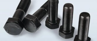
For reliable and high-quality fastening of 2 or more parts to each other, it is fundamentally important to select the correct dimensions of the fastening elements. This question often causes difficulties, because even the sizes of wrenches are selected taking into account the sizes of the fasteners themselves. Therefore, we will consider all the nuances that are important to consider when choosing the necessary hardware.
The main parameters by which bolts and nuts are selected are the diameter of the product, its thickness and length. But besides them, there is a number of important data, information about which is printed on the hardware. This:
- metric thread (it is designated as M);
- thread pitch (it can be especially small, small, large, especially large, in the latter case the value is not added, denoted as P);
- diameter of the product (designation – D);
- product length (denoted L).
The numbers next to the letter designation of the parameters are data indicated in millimeters. To find out the type, as well as correctly determine the size of, for example, a bolt, you must first find out what type of fastener is needed. Here it is permissible to use domestic GOST, European ISO quality standards or even DIN standards (Germany).
Bolt and nut sizes
All mechanisms in structural elements have certain types of bolted connections. Information on the connection is indicated by the manufacturer in the technical and also accompanying documentation. However, consumers may not always have access to such documentation, due to many factors. How then? In this case, you can quickly and accurately determine the dimensions of bolts and nuts:
- The size of a nut or hex bolt is determined by measuring the distance between two parallel edges. The diameter of the threaded part can be found without measuring with a ruler or caliper in the technical information for the fastening element. The marking on the hardware is indicated by the letter D.
- If you have a sample, you should examine it carefully. Often markings are indicated not only in the documentation, but also on the surface of the product. This simplifies the process of selecting fasteners. However, it happens that the bolts are damaged and the information indicated on the head is not readable.
- You can contact specialists who will instantly select a new fastener of the required size based on the sample. And they will offer bolts in bulk, the price and quality of which will meet all your requirements.
- Take measurements yourself. Note that the key characteristics are the overall dimensions, as well as the thread pitch and bolt diameters. It is necessary to know the basic technical parameters of bolts, since this will allow you to correctly determine the choice of tool size.
- You can use a caliper to measure the size of the head. It allows you to accurately determine the distance that is formed between the edges of the cap. When measuring, the obtained values should be transferred to a millimeter tape.
- When determining turnkey dimensions, attention should be paid to the length of the fastening element in question. It can be measured using a stationery ruler. The distance from the bottom of the head to the chamfer is measured.
- To determine the diameter of the bolt, it is recommended to use a micrometer or a template ruler. Experts recommend using a template, since with its help measurements are carried out as accurately and quickly as possible.
- Using a caliper, it is possible to accurately determine the thread pitch; in this case, the distance between individual turns is considered, but this measurement option is suitable for large-sized products. If you need to find out the step parameter of a small part, take 10 turns at once, measure the distance, and divide the result by ten. Note that there are M10 bolts, the dimensions of which are indicated in inches (1 inch = 25.4 mm). But sizes according to GOST are considered traditional in the CIS market.
- The bolt size is indicated in the technical documentation. It can be found in the markings applied to the surface of the product - the first two numbers indicate the diameter, the second - the length of the bolt, the third - the thread pitch. If the marking is not visible, then the size can be determined by measuring the length, thread pitch, and bolt diameter.
Dealing with this issue most often does not arise, but if you have any doubts, then it would be right to seek help from a specialist who will help you deal with the fasteners.
How are bolts marked?
Symbols are regulated by the state standard, first adopted back in 1977. The last update of the regulations dates back to 2006, however, as practice shows, there are still quite a lot of old-style fasteners in circulation - which means that full-fledged operation requires the ability to read not only new, but also previous markings.
The basic codification of hardware involves the use of digital and letter designations. For products manufactured by domestic manufacturers, the following algorithm is considered a characteristic feature: the letters are located at the top, while the numbers on the bolts are printed directly below them.
The first GOST, No. 22353-77, provides for a special decoding procedure. First, as a rule, comes the manufacturer's mark - each plant has its own identification symbol, which uses elements of the Latin or Cyrillic alphabet. The number series, in turn, begins with the resistance indicator. After the digital combination, the HL marking may also be indicated, indicating that the hardware belongs to the category of products that can withstand low-temperature conditions without loss of strength characteristics. On models with non-standard threads, a small arrow is applied, directed counterclockwise.
The changes contained within the framework of GOST R 52644, approved in 2006, provide for the indication in numbers of bolt strength parameters - in accordance with the updated table of standards - as well as the climatic area of operation, batch number, strength and dimensions. To designate the latter, the standard metric system is used - for example, a marker 16x32 means that the cross-section of the hardware is 16 and the length is 32 mm.
Wrench sizes
Today, there are universal wrench options that are great for working with different nut diameters. However, cases are different, and the need to select a tool cannot be ruled out. Several options are offered:
- Thread diameter. There is nothing complicated in this case. You can use special devices and tools that allow you to determine the parameters. Or, as an option, look at the information of interest in the technical documentation. Note that if the fastener has a standard thread diameter, then 2 sizes are offered, namely normal and reduced. However, this option is quite rare.
- Head diameter. Depending on the size, the distance of the edges will change: this is what needs to be determined. A ruler is suitable for this. If everything is done correctly, the bolt head will clearly fit into the selected wrench. Of course, it is not always possible to accurately measure a parameter with a ruler, so it would be better to use a caliper.
- Bolt length. The height of the head is not taken into account, only the shaft is considered. If an M16 bolt is required, the thread diameter dimensions should be 16 mm. The marking may also indicate other information: it shows the nominal height of the head, the thread pitch. If you have a car bolt with a pointed tip, then you need to calculate its length taking into account the guide.
General overview
Metal fasteners manufactured in accordance with GOST standards differ in many parameters - from diameter and thread size to material class. The information necessary to understand the specifics of a particular product is applied to the head or cap. Before choosing, you need to calculate strength indicators, clarify the chemical composition and resistance to certain categories of substances, and also take into account special requirements related to operating conditions.
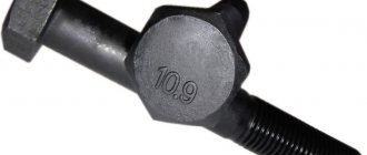
Markings
The class indicator - two numbers written through a dot, or sequentially - is one of the most significant characteristics. The first number is used to describe 1/100 of the nominal strength limit of the fastener, measured in MPa, the second shows the ratio of the yield and strength limits, which must be multiplied by 10 to obtain the final value. This, in fact, is the maximum working load of the hardware used - when calculating connections, a coefficient of 0.5-0.6 is used, which excludes exceeding the permissible norm.
What do the numbers on stainless steel bolts mean?
Austenitic products are marked indicating the specific type of alloy (A2, A4), as well as one tenth of the limit value (50, 60, 70) characteristic of carbon compositions.
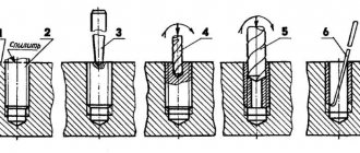
Types of threaded fastening
The considered principle of connecting elements is based on the use of at least two parts, the first of which has an external thread, and the second - an internal thread. The following types of configurations are distinguished:
- Bolted - the formation of through holes with the subsequent insertion of a rod tightened from the reverse side.
- Screw - in this case, the base itself acts as a retainer, the channels in which are prepared in advance, or - when using self-tapping screws - are formed during the integration process.
- Using studs, one of the ends is screwed into the component part, and the corresponding nut is screwed onto the second in a special way.
Pros and cons of threaded connections
The advantages that determine the demand in everyday life and industry for products with applied threads include:
- Versatility and reliability.
- Strength characteristics.
- Resistant to axial and lateral loads.
- Ease of installation and disassembly.
- Affordable cost of organizing work.
Among the shortcomings, one can note only the increased stress in the section of the depression profile, which necessitates the need for a competent choice of marking technique. Matching loads reduces the risk of accidental loosening or tearing.
Reading the markings
The order of arrangement of numeric and letter values is determined by the norms of the standard. Thanks to this, deciphering the technical specifications used in the implementation of construction, installation and production projects becomes much easier. A specialist who understands what the numbers on the head of the bolt mean can easily understand what specific fasteners we are talking about and what criteria should be used to select the material.
For clarity, it is worth examining the designations of fasteners, the technical characteristics of which are expressed using the following markings: A2M12x1.50 LH-4gx60.66. C.097. It is important to emphasize that, in accordance with the given sequence, the actual name must be indicated first. This applies to all marked products of the category in question, so in our case the word “bolt” will be placed before the alphanumeric combination.
The rest of the reading principle will look like this:
- The first in order is the letter A, which determines the accuracy class of the hardware. The existing gradation involves division into three groups (A, B, C), so in this example we are talking about the best possible option.
- Number 2 characterizes the performance format. The standards include 4 possible varieties, the first of which is not used for labeling.
- The letter M indicates the type of thread applied to the rod part of the fastener. There are three varieties - conical, trapezoidal and metric, which is discussed in this example.
- The number 12 is the millimeter diameter of the rod. It is curious that the combination of M12 markers is typical only for A-class products.
- 1.50 is a value characterizing the thread pitch. Moreover, in cases where the combination of dimensions is typical, inclusion in the description is not considered a mandatory condition.
- Similar to the previous point, the LH mark, indicating that a left-hand cut has been applied, belongs to the special category. If processing is carried out in a standard manner, the designation is excluded from the general list.
- The 4g marking on the bolt head indicates that the thread accuracy is at a basic level. The maximum possible indicator on the scale used is 8.
- The number 60 is the length of the hardware in millimeter terms.
- The number 66 is a strength characteristic, a dot is used to separate it from the previous value.
- C - grade of steel alloy selected during manufacturing. This particular marker is used in the production of fasteners made of “quiet” steel, while the letter A denotes “automatic” products.
- 097 - element coating. There are thirteen possible options, of which nine is galvanized. 7 in this case is the thickness of the outer layer in microns, equal to seven microns.
A designation on the bolt head that complies with a unified standard is a practical and convenient way to quickly and accurately select the required products. It is worth noting that the products of European and American manufacturers have a different description, including one that uses inches as the base measurement, so to read it you will need to use a conversion table.
What markings are applied to stainless bolts?
But in the case of hardware, for the manufacture of which austenitic steels are used, the alphanumeric code will differ from the previous version. Such products are usually marked as A2-50 or A4-60, with the possible addition of the manufacturer's mark at the beginning. The letter A and the number after it characterize the specific grade of the alloy, while the second group of numbers represents a value equal to one tenth of the tensile strength established for carbon-type models. Thus, the A4-80 marker applied to the fasteners will indicate that they are made of stainless material with the addition of molybdenum, and are capable of withstanding mechanical loads of up to 800 MPa, corresponding in their characteristics to elements made of carbon steel of category 8.8.
Strength classes of threaded fasteners
According to the standard classification, there are seven categories for nuts (4, 5, 6, 8, 9, 10, 12), which, as in the case of hardware, indicate 1/100 of the total limit value determined when calculating the pressure on the structure. However, there are also differences - in particular, these categories apply only to parts with a standard and high profile, while the designations 04 and 05 are applied to the sides of low models, indicating that this option is not suitable for operation under high load conditions.
Nuances associated with labeling
The generally accepted norms on which state standards are based correspond to the system developed by the International Organization for Standardization. In addition to the features and requirements already discussed, there are several more rules that must be taken into account by manufacturers of fasteners:
- Bolts and screws with a diameter of more than 6 mm are required to be marked, while for products with a smaller cross-section the procedure is voluntary.
- The alphanumeric designation is not applied to hardware with a cross-shaped or straight slot, as well as to fasteners made without stamping, while hexagons with any head shape must be designated in all cases.
- For marking, the end or side of the cap is used, while in the second option the method of applying in-depth marks is used. Convex elements are subject to restrictions directly related to the thread diameter - the maximum permissible value is 0.3 mm.
The geometry of various types of threaded fasteners is regulated by separate standards that require strict compliance.
Working principle of bolted connection
As a rule, a bolt is never installed alone - unless for a purely constructive purpose, without the task of withstanding a significant load. This solution is used if the goal is simply to fix one part relative to the other, to eliminate rotation, slipping, vibration, or to supplement the main fastening system.
In 99% of cases, bolted connections are presented in a group - from 4 to 36 products.
They are placed around a circle, in the corners of a symmetrical regular polygon (square, hexagon) or along a complex perimeter (along the line where the edges of the parts meet). The latter option is inherent in assemblies of housing parts - gearboxes, pumps, compressor equipment, etc.
There are three basic options for bolted connections:
- durable - aimed at resisting external loads;
- tight - designed to maintain the specified sealed position of the unit;
- tight-strong - when it is necessary to ensure both resistance to loads and complete tightness.
Most often you can encounter the third complex category, when tightening the bolts at the interface of the parts guarantees complete immobility of the product, even when the applied forces will “loose” and “pull” the elements in all directions. The most typical example of such an assembly is flanges with an intermediate seal.
During operation, the bolt experiences stress itself and has the same effect on the tensioned parts on which it is installed. When tightening, the total load is distributed in the form of two cones with the center relative to the axis of the bolt. This phenomenon is called a "pressure cone". Both cones demonstrate an increase in effective loads from the place where the bolt head or nut contacts the end of the part around the hole, to the plane of the joint of both parts. When exposed to external forces, all major micro- and macro-deformations also occur within the “pressure cone”.
During operation, the fastener simultaneously experiences:
- tightening force;
- bolt elongation when tightening;
- force that occurs when an axial force is applied to a node;
- bolt elongation when exposed to axial force;
- response resistance of parts that are deformed when tightened. At this moment, the supporting ends come closer together, and the degree of their movement (flattening) will depend on the compliance of the material.
If we simplify the entire diagram, then some of the loads are directed directly to the bolt, and some are directed to the compressed parts. But in total they are all converted into tension, which is experienced by the bolt, which is already partially stretched during installation. Add to this the possible effect of heating and the picture becomes even more extreme.
However, nothing simpler and more reliable than bolted connections has yet been invented. And the fasteners withstand any test with honor. The main thing is when thinking about the question of how to select a bolt, look for a solution based on its operating conditions, and not just “by eye.”
In a through hole with a nut
The classic bolt installation scheme is to pass it through two coaxial through holes and tighten it with a nut on the reverse side. There is an old engineering joke that a bolt "hangs" in a hole. In part, this comparison illustrates well the actual position of the fastener in the assembly.
When tightened, the rod bends slightly within the gap between its surface and the wall of the hole. Due to this bending, the bolt compensates for both the skew of the parts and the non-parallelism of their supporting ends, as well as their compliance (compression).
There are several designs of bolts for through holes:
- normal - with the same amount of gap between the rod and the walls of the hole along the entire length of the connection (usually 0.5..1 mm);
- with a reduced diameter of the smooth part of the bolt (with thinning);
- with thinning and two centering journals, which align the position of the bolt in the hole according to the clearance fit;
- with thinning, two necks and a centering belt in the middle;
- with an extremely reduced diameter of the smooth part (self-aligning).
The first type is the most common, otherwise it is called “hard”. This is a standard GOST fastener and is used for most assemblies, although it exhibits its properties best in short assemblies.
The remaining options are called “elastic” bolts. Reducing the diameter by 20..30% of the original opens up more room for bending during installation and tightening. Such products are optimal when working with shock loads.
For quite a long time, there was an opinion that when designing fastening joints, a minimum gap should be provided between the surface of the bolt and the walls of the hole in order to prevent bending of the rod. This is due to the fact that additional bending stresses negatively affect the overall load characteristics of the fastener. Later, this statement was partially refuted, but “elastic” type bolts still have not found widespread use - contrary to scientific evidence, they are much less trusted.
When installing, first place the bolt in the hole. A nut is attached to the output threaded end by hand until it comes into contact with the end of the part. Then the bolt is secured against turning by placing the key on the head and resting it on a convenient plane, and the nut is already tightened with a certain force. Most often, the operation is performed using ordinary metalwork tools, and the worker controls the tightening force according to his own feelings. In critical mechanisms, the connection is tightened with a torque wrench, controlling the preliminary deformation of the bolt.
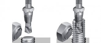
In a blind hole
Infrequently, but still sometimes, bolts are installed in assemblies according to the principle of a screw - screwing the product into the thread on the mating part. This option is used when placing the nut on the reverse side is structurally impossible or undesirable. This scheme should be avoided if possible.
Bolts in blind holes operate under much more stressed conditions than with a “traditional” placement. This is due to two phenomena:
- If transverse forces arise when the assembly is loaded, they wedge the threads and create local crushing stresses. Over time, the connection is guaranteed to weaken and self-unwinding may occur;
- in the area where the threaded end of the bolt enters the hole and begins to “pull” it towards itself by the threads, a zone of stress concentration is formed. Under heavy loads or frequent assembly and disassembly, this place will crumble. And if the nut can be easily replaced, then correcting a piece of the part is much more difficult, and restoring the original strength in that zone is virtually impossible.
A bolt installed according to the screw principle feels worst under alternating load cycles. It “wobbles” in the hole from side to side.
This installation scheme can only be used in non-critical structures or by taking additional measures to relieve the fasteners from the slightest displacement in the transverse direction. To do this, keys are placed in the assemblies, smooth pins and pins are hammered in, and smooth precise belts are machined on the bolts to remove the gap in the hole of the first part.
Features of marking high-strength hardware
Fasteners belonging to class 8.8 (or higher) represent a group of durable elements for which special requirements are imposed. This also applies to alphanumeric designations - for example, in accordance with GOST of 2006, the marking on the head of carbon steel bolts will look like W11.14 8.8S HL, where:
- W - manufacturer's mark.
- 11.14 - heat batch number.
- 8.8 is a parameter in which the product of the first number and 100 gives the maximum load for the thread, while the second number indicates a tenfold increase in the ratio of yield strength and strength.
- S - Compliance with the category of high-strength fasteners with a large hex head.
- HL - permissibility of operation at low temperatures.
Thus, deciphering the meanings used in labeling is also not particularly difficult - even taking into account the differences between the old and new standards.
Nut markings
In the case of elements of this category, a similar designation principle applies, however, due to limited space, the information is located on the side and is presented in an abbreviated format. To read completely, you will need the original packaging and accompanying specifications.
The marking order remains unchanged - name, accuracy level, thread type, diameter, pitch and direction (for non-standard cutting), strength characteristics and coating thickness in microns. At the same time, at the end of the description, GOST is indicated, which corresponds to the manufacturing technology of a specific model, which is why not all of the specified points are necessarily included in the designation.
The importance of choosing the right fasteners
The products offered by modern manufacturers differ from each other in terms of technical and functional characteristics. Bolts, studs, screws, nuts - to solve each specific problem, the appropriate equipment is required. The main indicators depend on the grade of steel used for manufacturing - when selecting a suitable option, it is worth paying special attention to the parameters that a particular alloy provides, as well as the conditions and the maximum load that can arise during the use of fasteners.