In the construction of multi-story industrial and civil buildings with large spans, columns, and massive trusses, I-beams are used. During the installation process, they need to be joined to each other and other building elements. Assembly joints of I-beams, which must be almost equal in strength to the rolled metal body, are made by welding or using fasteners. It is more difficult to manufacture them on a construction site than in a factory, due to the need for precise positioning and strengthening of the connecting points.
Docking of an I-column
If the joint is factory, then there is no problem.
In factories, profiles from separate parts are often joined together. Assembly joint? With a length of only 8 m? This already looks kind of strange. By rail, elements much longer than 8 m can be transported quite easily. srustam93
, your teacher (if you are a student) or your boss (if you are working) should answer your questions. Both of them receive money for their work and, for sure, they never refuse their salary. And there is no point for you to hang on forums and reinvent the wheel. They don’t work on forums (and don’t study!). Just like they don’t do this, for example, in smoking rooms. The forum does not exist to provide information to your entire work process. This is already the concern of your leaders.
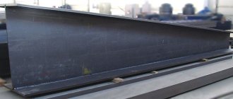
Where is it written how many parts a column can consist of, the minimum length of one part? I was told that no less than 1/3 or 1/4, but where is it written? beam 30K1 The project shows a joint with a gap of 50 mm, linings on the shelves, but the minimum length of one part is not indicated, column height 8150
Let's agree, everything is fine with this. 30K1 is docked, 35 is not. When I was counting how many 12-meter beams were needed to reduce the amount of scraps, it came out to 14 pieces. and the remainder of 5m is a single piece, but at the same time the shortest 750mm, which falls on the nodes. But they tell me that such a short one is not possible, and they cannot explain why clearly. As a result, we waited for the 15th beam, and without waiting we assembled the last column of three parts.
source
Column and wide-flange I-beams: main characteristics
For the manufacture of metal products operating under normal conditions, carbon steels of ordinary quality - calm and semi-quiet - are in demand. For critical products – low-alloy grades of type 09G2S. Production methods: hot rolling and welding. Hot rolled products are regulated by GOST 26020 or STO ASChM 20-93. The assortment of I-beams in these two regulatory documents is slightly different.
Compared to normal ones, wide-flange and column I-beams have increased flange width, flange and wall thickness. This reinforced design ensures high strength and rigidity of the products, but increases their weight. With proper calculation, I-beam structures are resistant not only to static but also to dynamic forces.
Features of bolted connections
To determine the method of how to properly join structural elements from an I-beam, it is necessary to know exactly the operating features of the object. The detachable type of joining of an I-beam is usually used when installing structures that are planned to be dismantled and reassembled several times. Performed using overlays, it has advantages and disadvantages.
Advantages of a bolted connection
- Relative ease of assembly, which can be performed by workers with a low level of qualifications.
- No residual stresses present in the weld.
- Simpler measures for checking the quality of connections, compared to checking the weld.
- There is no need to involve qualified welders in the work.
- Resistance to shock and vibration loads. However, in difficult operating conditions, periodic tightening of fasteners may be required.
The disadvantages of this method are higher (compared to welding) labor and metal consumption due to the need to use additional reinforcing elements, gradual corrosion destruction of fasteners made of “ferrous” steels.
Table of dimensional characteristics of column and wide-flange I-beams
| Range of characteristics | I-beams | |
| Wide shelf | Columned | |
| Wall height, mm | 193-718 | 196-431 |
| Shelf width, mm | 150-320 | 199-400 |
| Wall thickness, mm | 6,0-23,0 | 6,5-23,0 |
| Shelf thickness, mm | 9,0-36,5 | 10-33,5 |
| Weight 1 m, kg | 30,6-305,9 | 41,3-290,8 |
| Number of meters per ton | 3,27-32,7 | 3,44-24,21 |
Application of I-beams for the manufacture of centrally compressed columns
The functional purpose of such columns is to transfer loads acting from above to the base of the structure, and through it to the soil. These structural elements are subject to pressure from longitudinal forces, resulting in uniform compression of the cross section.
Structural components of centrally compressed columns:
- Header. Designed for fixing structures located above it.
- Kernel. Main load-bearing element.
- I-beam column base. Attached to the base with anchor bolts. Serves to distribute the applied force over the surface of the foundation.
I-beam columns, based on the cross-section of the rod, are divided into through (lattice) and solid. The height of the section can be constant in size or variable. When calculating the optimal column design, the following are taken into account:
- the amount of force applied;
- operating conditions;
- manufacturing capabilities;
- convenience of joining elements that provide additional support for the structure.
Design features of centrally compressed solid and lattice columns
For the manufacture of column structures with a solid and lattice cross-section, various types of metal products are used.
Solid section
In the production of these columns, column and wide-flange rolled I-beams can be used, as well as welded products with an H-shaped cross section. A welded I-beam is produced by joining three sheets of steel using economical industrial automatic welding. The cross-section of such products is not only constant, but also variable, providing the opportunity to save metal.
With lattice section
Such structures consist of two vertical branches, which are connected with braces or planks. The rigidly connected branches work together and provide significant stability and reliability. The axes passing through the branches are called “material”, and those parallel to them are called “free”.
The most durable option is to connect the branches with a triangular lattice made from braces. Such a lattice in the plane of the face represents a truss that perceives axial forces. It is used with a significant separation of branches - up to 800 mm - and/or an axial force of 2500 kN or more.
The distance between the flanges of two branches is determined in accordance with the conditions of equal stability of the rod. However, it is recommended to make it more than 15 cm to allow periodic painting of the internal surfaces, which is necessary to protect them from corrosive destruction.
source
Welded I-beam: independent calculation, production and installation
Metal welded I-beams have been used for the construction of structures and floors for a long time. But until this time in Russia its use was strictly limited to the sphere of industrial construction, i.e. when truly grandiose structures are erected, which should not care about anything.
And only in recent years have such types of I-beams begun to appear that can actually be used in the construction of new houses of an ordinary residential building. Are you thinking about just such an overlap? Then we will help you learn all the features of its manufacture!
About the new technology of private housing construction
Today, the production of welded I-beams has been launched throughout the country, and is in demand even in private housing construction. And all this is due to new design and architectural solutions! Their modern volumetric planning projects require special quality load-bearing frames and reliable ceilings, which will be most effective for large spans - from 7 meters.
You've probably noticed how country cottage houses and similar buildings differ in their appearance from the original Russian hut. Now imagine how different their architecture and construction principles are! That is why steel I-beams today have become actively used to cover spans from 4 to 18 m, and both carbon and low-alloy steel are used for their production, which guarantees the required qualities and strength.
For the manufacture of such beams there is even a GOST and the necessary certificates. Tangential stresses are taken up by solid walls, and compressive and tensile stresses are evenly distributed along the length. To make it more clear to you, the role of such a vertical wall is essentially the same as that of a zigzag lattice in a metal truss. Although at first glance such beams do not look too strong or monolithic:
What is a welded I-beam?
According to their type of section, I-beams today are usually divided into rolled or composite, which are also called welded. A welded I-beam is a special type of shaped rolled metal in the form of an inclined or horizontal beam. Today it is made from carbon and low-alloy steel, always of high quality.
Let's list the main advantages of welded I-beams:
- Cover large spans with significant loads.
- Ideally redistribute horizontal and vertical loads.
- They work well in bending due to the rigidity of the beam profile.
- They do not burn and do not lose their load-bearing capacity when heated even at fairly high temperatures.
- Resistant to biological influences.
- Excellent for the construction of prefabricated building structures.
- They allow a significant reduction in the weight of the entire structure compared to hot roots.
- They are also manufactured with a completely asymmetrical cross-section.
That is why such welded beams are used today in the construction of residential buildings, industrial complexes, and even bridges and tunnels. It would seem that such a beam would be too heavy for private house construction, but in fact, the use of steel I-beams can ultimately reduce the total weight of load-bearing structures. But remember that in relation to the ceiling made of welded steel I-beams, there are strict requirements:
Features of bolted connections
To determine the method of how to properly join structural elements from an I-beam, it is necessary to know exactly the operating features of the object. The detachable type of joining of an I-beam is usually used when installing structures that are planned to be dismantled and reassembled several times. Performed using overlays, it has advantages and disadvantages. Advantages of a bolted connection
- Relative ease of assembly, which can be performed by workers with a low level of qualifications.
- No residual stresses present in the weld.
- Simpler measures for checking the quality of connections, compared to checking the weld.
- There is no need to involve qualified welders in the work.
- Resistance to shock and vibration loads. However, in difficult operating conditions, periodic tightening of fasteners may be required.
The disadvantages of this method are higher (compared to welding) labor and metal consumption due to the need to use additional reinforcing elements, gradual corrosion destruction of fasteners made of “ferrous” steels.
Advantages of the welded beam production method
Today, metal I-beams for the construction industry are manufactured in two main ways: hot-rolling and welding. A welded I-beam has great advantages over a rolled one. It also has better strength characteristics, while its weight is lower by as much as 30%. And all thanks to the fact that the calculation of a welded I-beam involves a competent combination of different grades of steel. This is why a welded beam in industrial production is cheaper than a hot-rolled one.
Also, welding itself as a method is good in that with its help, metal beams can be made of a wide variety of sizes, even up to 4 meters or more in height, but all this is impossible to do with hot-rolled beams. In addition, only with this method is it possible to produce a beam with different widths along the entire length.
Why create beams with variable sections, you ask? The fact is that such beams are much more economical than shelves with a constant profile. After all, even a person who is far from construction understands that in different places of the beam after its installation it will have to be subject to different stresses: in some places it is almost not loaded, and in others it is subject to wear and tear. In such “important” places they make it thicker, and where possible they rationally save on material.
In addition, if we are talking specifically about a welded beam, then a variety of steel grades are used for its manufacture. This technique allows you to reduce metal consumption. Almost the entire beam is made of ordinary steel, the most stressed part is made of high-strength steel, and the least stressed part is made of low-carbon steel. Thanks to all this, the cost of the beam is reduced by 5%, which is quite noticeable.
Calculation and production of welded I-beam
High-quality welding of I-beams for floors will require a lot of attention and responsibility from you. You will need to calculate all the upcoming loads on the structure in general and on the joints of the beams themselves.
Just designing and planning I-metal welded beams takes a lot of time. Therefore, we recommend that you focus on the dimensions and purposes of finished products from manufacturers.
The modern market offers a fairly large variety of sizes of finished I-beams with their own designations and types. The dimensions of the beam are determined by the number, which indicates the distance between the outer edges parallel to each other.
For example, the marking K denotes columns and beams that must withstand enormous loads. Keep in mind that there is also a certain type of beams that are not used for floors, but only for creating heavy equipment and machinery. Such beams have their own manufacturing standards and properties.
Wide-flange designs are suitable for lighter loads. And the strength of such beams will directly depend on the length, the formula of the transverse profile, the use of raw materials and manufacturing methods, i.e. metal rolling technologies. Here is a standard welded beam for private housing construction:
Here are the parameters of welded steel I-beams for the manufacture of such beams:
How to weld a beam yourself?
If you already have some experience working with this material and you want to make welded beams for building your house yourself, you will need an alloy steel sheet as a base. The hot-rolled method of manufacturing at home is quite complicated, so welding is really better for you. This is a responsible task, so if you have the opportunity, it is more rational to immediately invite an experienced welder.
After the individual elements are ready, assemble the structure using the selected welding method. First you will need to install a vertical wall and secure the stiffeners and press everything down with clamps. The finished beam must be protected with a special coating so that it does not corrode in an aggressive environment.
How to avoid deformation?
If you make mistakes during the manufacturing process, you may encounter such unpleasant deformations of the beam, which in the future will significantly complicate the installation process:
Let us explain in more detail. Your main task when making welded beams is to then join the parts so that the seam does not work in tension.
You also take into account this important fact that the welding itself puts some stress in the beam, and this is not always noticeable to the eye. Therefore, it is advisable not to immediately weld the next part to it. Just push the seam back slightly and the beam will be level.
Comparisons: in order to avoid any deformation of the beam, especially for arranging an interfloor floor, it is subjected to special processing in the factory:
If you undertake making such a beam yourself, the following steps will help you figure it out:
I-beam connection technology
An I-beam, also known as an I-beam, is one of the most popular types of rolled metal in construction.
Its geometry allows it to withstand large longitudinal and transverse loads, which is why the I-beam is widely used in the installation of metal structures, including critical ones.
However, regardless of the use case, the strength of the final metal frame depends not only on the parameters and characteristics of the rolled product itself, but also on the correctness and method of connecting it to each other.
Methods for connecting I-beams
Their installation can be done in two ways: welding or bolting. Properly performed welding allows you to obtain a strong, reliable structure, but in some cases bolted or riveted connections can also be used, since the weld itself is a point of stress concentration in the structure.
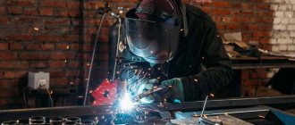
I-beam welding
Welding can be used in two situations: connecting an I-beam end-to-end when it is necessary to extend the beam (for example, when installing spans) or when cross-fastening a secondary beam to the main one. Butt welding is done in two ways.
Through the gasket
Between the ends of I-beams located in the same plane, a steel plate is placed, the size of which extends beyond the boundaries of their profile. The plate is welded using a fillet weld on both sides. The same method can be used to install rolled products of different sizes.
Among the advantages: relative simplicity - you only need to maintain the straightness of the longitudinal axis, and high speed of installation, since preliminary cutting of the edges is not required.
With overlays
Overlays can be used to further strengthen the joint. To do this, the edges of the wall (base) and shelves are pre-beveled to ensure high-quality penetration. The rolled product is welded around the perimeter while maintaining the straightness of the longitudinal axis.
Sheet steel linings are attached to the upper and lower planes of the shelves, as well as to the sidewalls of the wall with clamps. Their shape can be rectangular or, for greater convenience, diamond-shaped, with the obligatory observance of the symmetry of the shape relative to the longitudinal axis.
The final stage is welding of the linings around the perimeter.
Both methods are used only in cases where the structure is not critical and the load on the connection point will be insignificant.
Welding with secondary beam
This method of connecting I-beams is used in the construction of floors and load-bearing structures, and, despite the noticeably greater strength and reliability, it is performed almost as simply as the previous one.
In the upper flange of the main beam, cutouts are made in the shape of an equilateral triangle, and an overlay is welded to the lower flange. The top flange of the additional beam is given the shape of a triangle, corresponding to the shape of the cutouts in the main one. Its lower flange is cut to a length equal to the distance to the wall of the main I-beam.
The installation of the entire structure is carried out one by one: first, the main I-beams are mounted, then additional ones are docked and welded to them.
Bolted connection
This method, unlike the previous one, is detachable, therefore it is used mainly where dismantling of the structure may be required. Produced using overlays. Almost similar to a bolted connection - a connection with rivets, but dismantling part of the structure in this case requires destruction of the fasteners.
Pros:
- Easy to assemble - no special qualifications are required from the worker.
- At the attachment point there are no residual stresses characteristic of a weld.
- Checking the quality of a joint is much easier than checking the quality of a weld.
- Resistance to shock loads and vibrations.
Flaws:
- The need to periodically check bolted connections and tighten them, which in certain cases is quite difficult or even impossible.
- Higher metal consumption and labor-intensive work.
- Gradual wear of connections due to corrosion of bolts.
In general, the technology for connecting I-beams using bolts is almost completely similar to welding with overlays. Additionally, you only need to comply with:
- The distances between the centers of the holes must be at least 3 times the diameter of the rivets.
- The dimensions of the bolt heads and nuts - the distances between them should be sufficient for ease of use of the tool.
As noted above, both options are used in construction. The choice towards one of them is always based on additional requirements for the reliability of the structure and its operating conditions.
- Range of smooth reinforcement and its application Steel...READ MORE
- Corrugated steel and protective coating options Corrugated sheets, also known as corrugated sheets, are in fairly high demand in...READ MORE
- Correct fastening of corrugated sheets to the roof Corrugated sheets, also known as profiled sheets or corrugated sheets, in recent years...READ MORE
- Comparison of steel and composite reinforcement With the advent of more modern synthetic materials, metal…READ MORE
- Choosing corrugated sheeting for the roof In one of the previous publications, we talked in detail about how...READ MORE
- Calculation of the weight of a steel hexagon Steel hexagon is one of the types of high-quality products...READ MORE
- Types of pipes for water supply. Which ones to choose? What to consider during installation? A wide range is a double-edged sword. On the one hand, he...READ MORE
- Types and uses of welded mesh Welded mesh is a “web” formed from ...READ MORE
- Bent steel angle: GOST, types, application Bent steel angle is not the most popular, but still sufficient...READ MORE
- Corrugated steel sheet: standards, types, sizes, weight, use Corrugated sheet is a type of sheet metal, distinguished...READ MORE
- Delivery, acceptance and proper storage of reinforcement Steel reinforcement is an indispensable attribute of almost any...READ MORE
- Steel strip as an element of the ground loop With the growing number of various consumer electronics in every...READ MORE
- Which is better, a channel or an I-beam? Which rental is stronger? I-beam and channel can be considered one of the most popular types...READ MORE
- When and why do you need to use metal pipes for laying cables and wires? Rolled pipes have a fairly wide range of applications, including...READ MORE
- Calculation of the weight of the binding wire Calculation of the weight of the wire may mainly be required in two situations...READ MORE
- Checking the quality and tightness of the welded seam of pipes and structures Quite stringent requirements are imposed on the installation of rolled metal...READ MORE
- Features of using a channel when tying a foundation A channel is one of the types of shaped steel, distinguished...READ MORE
- Instructions on the procedure for accepting products by quantity P-6 Approved by a resolution of the State Arbitration Court under the Council of Ministers of the USSR dated...READ MORE
- Hardware for all occasions Strictly speaking, the term “hardware” (an abbreviation for “...READ MORE
- Laser metal cutting technology…READ MORE
- Metal corrosion Metal corrosion, colloquially called rust, is the disintegration of...READ MORE
- Metal structures Modern industrial landscape nevo…READ MORE
- Corrugated sheeting for everyone Corrugated sheeting...READ MORE
- Characteristics and application of expanded metal The range of metal products produced, even without taking into account the standard size...READ MORE
- Barbed wire for war and peace For modern man, barbed wire is an object strongly associated with...READ MORE
- Installation of a profile pipe: methods and necessary accessories Profile pipe is one of the most convenient options for metal...READ MORE
- Welding electrodes UONI: features, characteristics, use The modern market offers a wide selection of different products for ...READ MORE
- Rolled metal - materials and technologies Rolled metal is, strictly speaking, the very material that defines...READ MORE
- Connecting channels: methods and techniques Due to its shape, which has perpendicular stiffeners, the channel...READ MORE
- Seamless pipes - production and application ...READ MORE
- Wire GOST 3282-74 Steel wire is the simplest and most widely known product made from steel...READ MORE
- Special steel: composition, production, processing New industries that rapidly developed in the second half ...READ MORE
- Powder coating of metal products Painting for metal products is an absolutely necessary procedure...READ MORE
- Punching holes in metal: features of technology Punching holes in metal is one of the perforation methods. …READ MORE
- Metal cutting: from chisel to machine Metal cutting is one of the main methods of metalworking, p...READ MORE
- Instructions on the procedure for accepting products for quality P-7 Approved by a resolution of the State Arbitration Court under the Council of Ministers of the USSR dated...READ MORE
- Metal mesh - types and production Metal mesh is one of the most popular types of steel...READ MORE
- How does the grade of steel of seamless pipes affect their use? The use of any type of metal products depends immediately on...READ MORE
- What is bar metal, and how does it differ from others? The entire mass of rolled metal produced by manufacturers can be divided...READ MORE
- I-beam connection technology I-beam, also known as ...READ MORE
- Why do you need a steel I-beam? …READ MORE
- Wire rod and wire - production and use Wire is one of the most popular types of metal products. …READ MORE
- Profile pipe - materials, production, application Pipe metal products are intended not only for creating pipelines...READ MORE
- Production and characteristics of I-beam ...READ MORE
- Types and brands of welding electrodes Welding metals using a voltaic arc appeared in the 19th century and...READ MORE
- Methods of galvanizing metal Iron and steel are the materials from which the skeleton of a modern...READ MORE
- Welded pipes - technology, application, advantages The 21st century is the century of pipelines. Pipes for oil and gas transportation...READ MORE
- Assortment of rolled metal: main types, definitions and GOSTs Assortment of rolled metal produced by modern industry ...READ MORE
- Channel - use and load Channel is one of the types of shaped steel products. In cross...READ MORE
Advantages of working with us An order for any metal will be delivered on the day of the order if your order is received before 12:00 Deferred payment to our regular customers We assemble the entire created order into one machine Quality certificates for all our metal We provide professional advice on selection Metal shipment 24/7 (24 hours a day, seven days a week) We will carry out rough processing, cutting to size, cutting metal, galvanizing pipes, meshes. We will unwind rolls, unwind cold and cold rolls and OC rolls, longitudinal and transverse cutting. We will produce, pipe blanks up to 2 meters, plates, gussets. We will do it, non-standard operations for bending channels and other rolled products in a short time Wide range available in stock Any type of product can be purchased from us starting from one piece Fast delivery 7 days a week throughout Russia Entry passes to the Third Transport Ring and the Garden Ring
Fastening units for welded I-beams
So, now let's understand the support nodes of metal I-beams. Their support on a steel column (support) can be rigid or hinged, that is, movable.
The connection of finished welded beams to each other during the installation process can be done in two ways:
- The first of which is that the I-beams are first welded to a special plate, and welding is carried out along the contour of the profile using fillet welds. The advantage of this particular method is that it is not necessary to separate the edges of the beams.
- The second method is to use overlays that are mounted symmetrically to the longitudinal axis, cut and welded with oblique seams. Thanks to this, it is possible to avoid problems with applying a weld along the entire side of the overlay. This welding method is suitable for structures with little future load, i.e. just for the construction of a private residential building.
- Welded beams can also be connected using a bolted connection - this is a detachable method, which is necessary to ensure that there is no residual stress in the structure, and the floor structure itself is resistant to shock and vibration loads. And also when it is not possible to invite professional welders.
Here is an interesting video comparing both types of beam connections:
As you already understand, in most cases, a metal welded beam is connected by welding, less often with bolts and even less often with rivets. All this directly affects the cost of installing such beams.
As for rivets, working with them is the most labor-intensive, although sometimes, unfortunately, you cannot do without such elements. For example, if the beam will be constantly subject to vibration (such equipment will be used), then it cannot be connected too rigidly to the structure.
If you are going to connect the entire metal structure with bolts, then:
- You will need normal and high precision fasteners. Only in places where there will be a shear load, bolts of normal or rough accuracy should not be used.
- You will need to make gaps in the beam in advance (or order something similar at the factory) so that the outer diameter of the hole itself is only 2-3 mm larger than the outer diameter of the bolt. This design will be resistant to deformation, and assembly is generally simpler.
- Precision bolt connections are well suited for hard-to-reach areas where riveted connections are not possible. But here the diameter of the holes needs to be increased by 0.3 mm so that the fasteners can easily withstand the upcoming load.
So, let’s now consider such an important stage as welding the main beam with the secondary one. Do everything step by step:
- Step 1. At the top of the main beam, make a triangular cutout of the exact size.
- Step 2. Weld the trim to the bottom of the main beam.
- Step 3. Make cuts in the bottom of the auxiliary beam that will be equal to half the width of the bottom of the main beam.
- Step 4. Now the top of the secondary beam needs to be formed into a triangular shape, the same as the top of the main beam was cut.
- Step 5. Next, we carry out installation: first the main beam, then the secondary one, and all this using the method of using an overlay.
- Step 6. And finally, the last stage is the installation of the junction of the upper parts and walls, where the overlay is also welded to the lower parts of the beams.
You can also fasten metal I-beams to each other using the bolt connection method. This method is necessary when from time to time you have to install or dismantle a specific unit. The advantage of such a connection is that there will be no residual stress in the structure. Which in itself is good, because then the ceiling will be more resistant to shock loads, and, in addition, you will not need to invite a professional welder to create the unit.
Rigid node: for static loads
Those. the beam can rest on top, directly on the center of the column profile, or the beam can be attached to the side. Then only a compressive load arises in the column, but the action of all forces occurs, so it has to be made stronger and more reliable, and this is an overconsumption of metal.
Sometimes it is also necessary to lay two beams across a span, then they are connected to each other using bolts and plates are installed between the two ribs. It is important to remember that metals are subject to thermal expansion due to temperature changes, and therefore you need to leave a small distance for their unnoticeable movement.
To transmit transverse pressure force, the rib of the beam is placed so that during installation it is directly above the column flange. In this case, the beam is connected to the column using a special overhead plate, and preferably immediately on both sides. But in such a way as not to create too tight a knot.
Here is a good example of how welded beams are combined on two spans so as not to create point stress on the intermediate floor wall:
To create a rigid beam connection, you will need a bolted or welded connection:
Hinge joint: for dynamic loads
Now about the hinged support of the welded beam. It is created using a support rib on the support table, where the entire load will be transferred. You will need to make the table itself from sheet steel.
Weld a table on three sides of the beam and make its width 2-3 cm larger than the rib of the beam. So the supporting edge should lie completely on the supporting table.
Features of welded joints
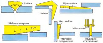
A reliable way to create joints between beams and I-beams is welding. When performing butt welding, weld quality control must be carried out. Most often, reinforcing pads are used to increase the reliability of the unit. One of the options for lengthening an I-beam is to weld rolled profiles on both sides to the gasket along the perimeter of the I-beam. No edge cutting required. The second method is to connect I-beams end-to-end, followed by welding on four reinforcing plates, the selection of the shape of which depends on the position of the I-beam in space. Overlays are welded to each shelf and to each side of the wall. Stages of work production:
- A bevel is made on the edges of the I-beam, ensuring good weld penetration.
- Linings are prepared from sheet steel. Rectangular reinforcing elements welded onto shelves must have the width of the shelves, and on the wall - the height of the wall.
- The overlays are placed on the seam, welded around the perimeter, pressing with a clamp. For ease of work, the wall linings are made diamond-shaped. The main requirement is that the overlay must have a shape that is symmetrical relative to the longitudinal axis of the I-beam.
Welding I-beams using pads and spacers is used to create structures that are not subject to significant loads. This is due to the fact that the seams along which these reinforcing elements are welded are stress concentrators. Another problem with welds is rapid aging. To combat this negative phenomenon, primers are used. Welding is performed with the beams in a fixed position. To do this, they are laid on rigid foundations, most often on specialized foundation racks.
Additional functions of an I-beam in private housing construction
The floor itself does not necessarily have to consist only of metal I-beams. Often they are used only in the most intense places, and wooden I-beams are installed between the metal parts.
Why is that? The fact is that welding requires highly qualified workers. Further, in ordinary literature and Internet sites there is not that variety of components and ready-made design diagrams for installing such a ceiling; a competent engineer is really required here, and even we only give recommendations. In addition, metal is not cheap. And the quality of welding is very important. It must work for a long time, even under conditions of corrosion or changing loads.
Therefore, this option not only has the right to life, but is also quite practical:
And finally, a metal I-beam often serves as an additional functional element, which has value in any household:
source
Features of bolted I-beam connections
Bolts are used to create a strong detachable connection. This method is justified when installing temporary supports or in cases where the possibility of dismantling metal structures is assumed.
Features of I-beam connections with bolts:
However, in the case of a bolted connection, the fasteners must be constantly checked and tightened. In some cases, such close attention to beams is difficult or even impossible. The method is labor-intensive and high consumption of rolled metal for fastening I-beams together. Over time, the bolts wear out and may become rusty, so there is always a risk of the fasteners breaking.
Joints of beams and columns
JOINTS OF BEAM AND COLUMNS
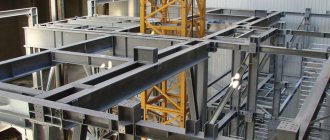
Most industrial and commercial steel buildings are frame structures consisting of columns, floor beams, trusses or transoms. As a rule, such buildings often have large spans and heights, which forces manufacturers and builders to widely use butt joints in various elements of steel building structures.
Mounting joint on overlays using a bolted connection
Preparing the joint for welding. Cutting edges and installing on guide strips.
Joint after welding, seam cleaned, guide plates cut off
The use of factory joints is primarily due to economic reasons and the size of the rolled metal. From the experience of producing metal structures in recent years, in the construction of industrial buildings in 80% of cases a normal, column or wide-flange beam is used according to STO ASChM 20-93, GOST 26020-83, and about 20% is a welded beam of variable section. The standard length of I-beams is 12.0 m, sheet metal is 6.0 m, in order to reduce the costs of cutting materials, it is necessary to prepare the sending elements in an increasing manner. For example, with a column length of 10800mm, from one rolled beam of 12000mm we get a blank for a whole column of 10800mm and a remainder of 1200mm, we get the next column by building up a new rolled beam with the resulting remainder (1200+12000=13200) and again we cut off 10800, then with the resulting with the remaining 2400mm we proceed in the same way as described above and so on. With a sheet composite beam we do the same thing directly when cutting the sheet, but on the beams themselves the joint is not made in one plane, but spread apart, the wall is welded in one place, the shelves are joined at an angle of 60 and welded above and below the wall joint. Of course, in both cases it is necessary to take into account the location of the joint, preventing it from falling into the zone of maximum loads and the junction of other structural elements. The factory joint on columns and beams is carried out according to the calculation conditions in accordance with SNiP II-23-81*; most often in factory realities, a welded butt seam is used with full penetration and cutting of the edges of the chords and walls of the mating parts. In cases where it is necessary to ensure the reliability of the joint and the base metal in areas of significant moments and shear forces, the joint is reinforced with overlays installed on the flanges and walls of the beam. To optimize the process of designing CM or developing CM in the production of metal structures, you can also use the standard series 2.400-10 “Normals of factory joints of profiles in building steel structures”, where the equal strength of the joint with the base metal has already been calculated and design solutions for the joints of the joined elements from channels have already been given, corners and I-beams.
Assembly joints are made due to the limited possibilities of transporting large-sized metal structures by road and rail; when their length is more than 15 meters, from the point of view of convenience and economy, it is more expedient to divide the structure into smaller elements for delivery to the consumer. The combination of shipping elements into one whole is carried out directly on the construction site by the installation organization. Assembly joints of beams and columns are made welded or bolted; compared to factory ones, they are more labor-intensive and costly due to the need to use additional elements to strengthen and position parts at the interfaces. The best option, of course, is welded, butt-butt with full penetration, subject to separation of the edges and a physical control method, however, during installation, the conditions for welding and quality control of seams do not always correspond to the design ones, therefore, as a rule, assembly joints are initially made on overlays reinforcing the strength of the joint. Bolted assembly connections are also made on overlays, preferably using high-strength bolts; such connections are metal-intensive, require significant labor costs in production, and the holes weaken the cross-sections of the elements, however, from an installation point of view, they are easier to assemble and do not require highly specialized personnel to make a high-quality joint . Flange connections are quite effective, but are not widely used due to their increased deformability. According to SP 16.13330.2011 - “the joining of columns during installation must be done with milled butt-welded ends, or on plates with welded or bolted connections, including high-strength bolts; it is also allowed to use flange connections that absorb tensile force with bolts, and compressive force through clamping surfaces flanges."
source
Joining I-beams
In the construction of multi-story industrial and civil buildings with large spans, columns, and massive trusses, I-beams are used. During the installation process, they need to be joined to each other and other building elements.
Assembly joints of I-beams, which must be almost equal in strength to the rolled metal body, are made by welding or using fasteners.
It is more difficult to manufacture them on a construction site than in a factory, due to the need for precise positioning and strengthening of the connecting points.
Features of joining I-beams
The main option for using shaped bars with an H-shaped cross-section is as elements of beam cages. The connection of beams in such structures is carried out in a horizontal plane or supported from above.
At the point of support for the end of the I-beam, supporting stiffeners are created. They serve to distribute and transfer the load from the I-roll to the support.
Features of welded joints
A reliable way to create joints between beams and I-beams is welding. When performing butt welding, weld quality control must be carried out. Most often, reinforcing pads are used to increase the reliability of the unit.
One of the options for lengthening an I-beam is to weld rolled profiles on both sides to the gasket along the perimeter of the I-beam. No edge cutting required.
The second method is to connect I-beams end-to-end, followed by welding on four reinforcing plates, the selection of the shape of which depends on the position of the I-beam in space. Overlays are welded to each shelf and to each side of the wall.
Stages of work production:
- A bevel is made on the edges of the I-beam, ensuring good weld penetration.
- Linings are prepared from sheet steel. Rectangular reinforcing elements welded onto shelves must have the width of the shelves, and on the wall - the height of the wall.
- The overlays are placed on the seam, welded around the perimeter, pressing with a clamp. For ease of work, the wall linings are made diamond-shaped. The main requirement is that the overlay must have a shape that is symmetrical relative to the longitudinal axis of the I-beam.
Welding I-beams using pads and spacers is used to create structures that are not subject to significant loads. This is due to the fact that the seams along which these reinforcing elements are welded are stress concentrators. Another problem with welds is rapid aging. To combat this negative phenomenon, primers are used.
Welding is performed with the beams in a fixed position. To do this, they are laid on rigid foundations, most often on specialized foundation racks.
Features of bolted connections
To determine the method of how to properly join structural elements from an I-beam, it is necessary to know exactly the operating features of the object. The detachable type of joining of an I-beam is usually used when installing structures that are planned to be dismantled and reassembled several times. Performed using overlays, it has advantages and disadvantages.
Advantages of a bolted connection
- Relative ease of assembly, which can be performed by workers with a low level of qualifications.
- No residual stresses present in the weld.
- Simpler measures for checking the quality of connections, compared to checking the weld.
- There is no need to involve qualified welders in the work.
- Resistance to shock and vibration loads. However, in difficult operating conditions, periodic tightening of fasteners may be required.
The disadvantages of this method are higher (compared to welding) labor and metal consumption due to the need to use additional reinforcing elements, gradual corrosion destruction of fasteners made of “ferrous” steels.
Combined joining of I-beams
To create large spans, a combined I-beam connection method is used, combining bolted joints and welding. Work order:
- connecting beams using overlays and threaded fasteners made of high-strength steel;
- belt welding;
- closing technological windows using linings and gaskets.
Joining I-beams, 5.0 out of 5 - total: 5
How to weld I-beams
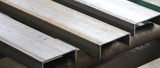
Steel beams with an I-beam cross-section are designed for universal use in mechanical engineering and construction. When studying the nature of stresses arising in loaded products having a solid cross-section, the unevenness of their distribution was revealed.
Sections of the cross-section of parts with the highest stress values were identified. As a result of this, the idea arose of creating a product with a cross-sectional shape where the mass of metal is concentrated in the most loaded areas. This is how the I-section appeared.
Production and use
Due to their ability to withstand heavy bending loads in different planes, shear and torsion, steel I-beams form the basis of load-bearing structures of prefabricated frame buildings and ceilings.
In-shop lifting mechanisms (beam cranes and overhead cranes) move along guides made from I-beams.
The production of I-beams is carried out in two ways:
- method of rolling solid castings. Such I-beams are called hot-rolled;
- electric arc welding of pre-cut sheet blanks, resulting in a welded prefabricated I-beam.
Hot-rolled I-beams are produced on rolling mills of metallurgical enterprises. This technology makes it possible to obtain a one-piece product that does not contain seams and is highly durable.
Assembly and welding of I-beams is carried out on automatic lines. Such a beam is slightly inferior to a solid-rolled beam in terms of strength, but can be made to special order, taking into account the requirements of a specific project.
The production of hot-rolled I-beams is carried out in accordance with GOST 26020-83; manufacturers produce welded I-beams according to their own technical conditions (TU).
Production technology
In the typical version, an I-beam is made from three sheet blanks: a wall and two flanges, welded to its ends at right angles. Manufacturing is carried out on specialized assembly lines configured to produce beams of a certain size.
The workpieces are moved on special rollers and pre-fixed in the desired position by clamping devices equipped with a hydraulic or pneumatic drive.
On the section of the assembled beam fixed by the clamping device, tacks are made by welding along the waist seam. After this, the beam moves along the rollers, is secured again, and its next section is tacked by welding.
The waist seam is finally welded after the entire structure is pre-fastened with welded tacks.
Welding of T-joints between the wall and the flanges is carried out automatically under a layer of flux. The automatic welding process can be performed with different devices. These can be welding manipulators, the torches of which weld, moving along given trajectories through articulated joints with several degrees of freedom.
Simpler devices such as self-propelled welding tractors, which are much more suitable for creating straight connections, can also be used.
Another class of devices capable of automatically welding waist seams of I-beams is cantilever or portal installations. In addition to the welding equipment itself, they include equipment for monitoring and quality control of the weld, as well as devices for supplying flux and subsequent cleaning of the seam from its residues.
Such installations carry out welding at an optimal angle of 45 °, which ensures the most favorable location of the weld pool and, accordingly, high quality of the weld.
Intense heating of the workpieces during the welding process leads to warping of the shelves. For this reason, the process of assembling I-beams includes a procedure for leveling them, carried out on special machines to correct the mushroom shape.
At the final stage of manufacturing, the ends of the product are milled.
Joining of I-beams GOST
Steel beams with an I-beam cross-section are designed for universal use in mechanical engineering and construction. When studying the nature of stresses arising in loaded products having a solid cross-section, the unevenness of their distribution was revealed.
Sections of the cross-section of parts with the highest stress values were identified. As a result of this, the idea arose of creating a product with a cross-sectional shape where the mass of metal is concentrated in the most loaded areas. This is how the I-section appeared.
Production and use
Due to their ability to withstand heavy bending loads in different planes, shear and torsion, steel I-beams form the basis of load-bearing structures of prefabricated frame buildings and ceilings.
In-shop lifting mechanisms (beam cranes and overhead cranes) move along guides made from I-beams.
The production of I-beams is carried out in two ways:
- method of rolling solid castings. Such I-beams are called hot-rolled;
- electric arc welding of pre-cut sheet blanks, resulting in a welded prefabricated I-beam.
Hot-rolled I-beams are produced on rolling mills of metallurgical enterprises. This technology makes it possible to obtain a one-piece product that does not contain seams and is highly durable.
Assembly and welding of I-beams is carried out on automatic lines. Such a beam is slightly inferior to a solid-rolled beam in terms of strength, but can be made to special order, taking into account the requirements of a specific project.
The production of hot-rolled I-beams is carried out in accordance with GOST 26020-83; manufacturers produce welded I-beams according to their own technical conditions (TU).
Production technology
In the typical version, an I-beam is made from three sheet blanks: a wall and two flanges, welded to its ends at right angles. Manufacturing is carried out on specialized assembly lines configured to produce beams of a certain size.
The workpieces are moved on special rollers and pre-fixed in the desired position by clamping devices equipped with a hydraulic or pneumatic drive.
On the section of the assembled beam fixed by the clamping device, tacks are made by welding along the waist seam. After this, the beam moves along the rollers, is secured again, and its next section is tacked by welding.
The waist seam is finally welded after the entire structure is pre-fastened with welded tacks.
Welding of T-joints between the wall and the flanges is carried out automatically under a layer of flux. The automatic welding process can be performed with different devices. These can be welding manipulators, the torches of which weld, moving along given trajectories through articulated joints with several degrees of freedom.
Simpler devices such as self-propelled welding tractors, which are much more suitable for creating straight connections, can also be used.
Another class of devices capable of automatically welding waist seams of I-beams is cantilever or portal installations. In addition to the welding equipment itself, they include equipment for monitoring and quality control of the weld, as well as devices for supplying flux and subsequent cleaning of the seam from its residues.
Such installations carry out welding at an optimal angle of 45 °, which ensures the most favorable location of the weld pool and, accordingly, high quality of the weld.
Intense heating of the workpieces during the welding process leads to warping of the shelves. For this reason, the process of assembling I-beams includes a procedure for leveling them, carried out on special machines to correct the mushroom shape.
At the final stage of manufacturing, the ends of the product are milled.
Replacement with channels
In practice, when constructing building structures, welding channels to each other is sometimes used to obtain an I-section. If channels are used instead of I-beams provided for in the design, such replacement must be approved.
Agreement on the use of alternative material is reflected by changes made to the relevant sections of the detailed design. The possibility of replacement is determined based on the results of strength verification calculations performed by designers.
The method used to weld the channels together is also determined by calculation. This can be welding with a continuous or intermittent seam, or using connecting pads.
When welding channels with a continuous seam, as a result of thermal deformations of the metal, twisting of the profile may occur. This phenomenon can be avoided by using special clamps, as well as by applying welding seams in small sections, alternating the sides of the profiles being connected.
If it is necessary to lengthen such a structure, the channels are butt welded. The locations of the butt welds of the channels forming the I-beam should not coincide with each other. To strengthen the structure, the weld can be reinforced with a pad.
Methods for connecting I-beams
When installing beam structures, welded connections of elements are made in various combinations. Among them are typical methods for connecting I-beams.
Butt-butt
To join using the “butt” method, the welded fragments are joined with pre-treated ends. The processing consists of making angular bevels on the end cuts for deeper welding of the joint.
Taking into account the load-bearing functions of I-beams, their connection is not limited to making end seams. To strengthen the joining area, four overlays are usually used - one on each of the shelves, and one on each side of the wall.
Overlays are rectangles made of sheet metal. They are placed over the connecting seam, then welded around the perimeter. Shelf linings are made for the entire width of the I-beam shelf, wall linings are made for the entire height of the wall.
Right angle
This connection is made between the main and secondary load-bearing I-beams of the frame structure, located on the same level. In this connection, the main beam serves as a secondary support.
Welding work is performed in the following sequence. In the upper flange of the main I-beam, a cutout is made in the shape of an isosceles triangle with an angle close to a right angle.
The joint flush fastening of two perpendicular I-beams thus obtained is reinforced by a sheet plate welded from below.
Welding an I-beam with a channel at right angles
This connection is made if the secondary I-beam is a channel. If the walls of the I-beam and the channel are the same in height, you can proceed as follows.
The upper flange of the channel is cut at an angle of 45°, and a similar-shaped cutout is made on the upper flange of the I-beam. The lower flange of the channel is cut in such a way that when joining, the cut is aligned with the lower flange of the I-beam, and the wall of the channel rests against the wall of the I-beam. Just as in the previous case, the connection is strengthened with an overlay from below.
Engineering thought does not stand still. In addition to the described welding technologies, newly created ones can be used; outdated welding equipment is replaced by updated, modernized or fundamentally new ones. It is possible that traditional welding will someday give way to another technology of permanent connections.
Joining unit for I-beam elements | Construction handbook
Category: News, Reference data, Construction
Joints of I-beam elements according to GOST 26020-83 and GOST 8239-89.
Constructive solution.
The design of the joint, the dimensions of the butt pads and welds, depending on the type of I-beams, the steel of the I-beams and pads, the type of electrodes or the brand of welding wire, must correspond to those indicated in this drawing and Table 1
Table 1.
Steel elements and linings grade C245. Type of electrodes E42, E42A. Welding wire grade Sv-08A
| Profile number | Shelf overlay | Wall trim | ||||||
| section b1xt1, mm | length l1, mm | weight 1 piece, kg | weld leg kf1, mm | section b2xt2, mm | length l2, mm | weight 1 piece, mm | weld leg kf2, mm | |
| 12B1 | 80x6 | 200 | 0,75 | 4 | 100x4 | 90 | 0,28 | 4 |
| 12B2 | 80x6 | 200 | 0,75 | 5 | 100x4 | 90 | 0,28 | 4 |
| 14B1 | 90x6 | 200 | 0,85 | 5 | 100x4 | 110 | 0,35 | 4 |
| 14B2 | 90x8 | 230 | 1,3 | 5 | 100x4 | 110 | 0,35 | 4 |
| 16B1 | 100x6 | 230 | 1,08 | 5 | 100x4 | 120 | 0,38 | 4 |
| 16B2 | 100x8 | 230 | 1,44 | 6 | 100x5 | 120 | 0,47 | 5 |
| 18B1 | 110x8 | 230 | 1,59 | 6 | 100x4 | 140 | 0,44 | 4 |
| 18B2 | 110x8 | 260 | 1,8 | 6 | 110x5 | 140 | 0,6 | 5 |
| 20B1 | 120x10 | 300 | 2,83 | 6 | 110x5 | 150 | 0,65 | 5 |
| 23B1 | 130x10 | 340 | 3,47 | 6 | 110x5 | 180 | 0,78 | 5 |
| 26B1 | 140x10 | 340 | 3,74 | 6 | 110x5 | 210 | 0,91 | 5 |
| 26B2 | 140x10 | 390 | 4,29 | 6 | 110x5 | 210 | 0,91 | 5 |
| 30B1 | 160x10 | 390 | 4,9 | 6 | 110x5 | 240 | 1,04 | 5 |
| 30B2 | 160x10 | 440 | 5,43 | 6 | 110x5 | 240 | 1,04 | 5 |
| 35B1 | 170x10 | 350 | 4,67 | 8 | 120x5 | 290 | 1,36 | 5 |
| 35B2 | 190x10 | 390 | 5,82 | 8 | 120x5 | 290 | 1,36 | 5 |
| 40B1 | 200x10 | 410 | 6,44 | 8 | 120x6 | 330 | 1,86 | 6 |
| 40B2 | 190x12 | 470 | 8,41 | 8 | 130x6 | 330 | 2,02 | 6 |
| 45B1 | 200x12 | 480 | 9,04 | 8 | 130x6 | 370 | 2,26 | 6 |
| 45B2 | 210x14 | 500 | 11,54 | 10 | 140x8 | 370 | 3,25 | 8 |
| 50B1 | 220x14 | 510 | 12,33 | 10 | 140x8 | 420 | 3,69 | 8 |
| 50B2 | 230x140 | 570 | 14,41 | 10 | 150x8 | 420 | 3,96 | 8 |
| 55B1 | 250x14 | 530 | 14,56 | 12 | 150x8 | 460 | 4,33 | 8 |
| 55B2 | 250x16 | 580 | 18,21 | 12 | 150x8 | 460 | 4,33 | 8 |
| 60B1 | 260x16 | 600 | 19,59 | 14 | 160x8 | 510 | 5,12 | 8 |
| 60B2 | 260x18 | 660 | 24,25 | 14 | 160Х8 | 510 | 5,12 | 8 |
| 70B1 | 300x16 | 660 | 24,87 | 14 | 170x10 | 610 | 8,14 | 10 |
| 70B2 | 310x18 | 680 | 29,79 | 16 | 180x10 | 610 | 8,62 | 10 |
| 80B1 | 320x18 | 680 | 30x75 | 16 | 200x12 | 700 | 13,19 | 12 |
| 80B2 | 320x20 | 690 | 34,67 | 18 | 200x12 | 700 | 13,19 | 12 |
| 90B1 | 340x20 | 710 | 37,9 | 18 | 220x12 | 790 | 16,37 | 12 |
| 90B2 | 340x22* | 790 | 46,39 | 18 | 220x12 | 790 | 16,37 | 12 |
| 100B1 | 360x22* | 800 | 49,74 | 18 | 220x16 | 880 | 24,32 | 16 |
| 100B2 | 360x25* | 930 | 63,59 | 18 | 240x16 | 880 | 26,53 | 16 |
| 100B3 | 370x28* | 950 | 77,26 | 20 | 240x16 | 880 | 26,53 | 16 |
| * The linings marked with an asterisk are made of steel grade C255. |
Replacement with channels
In practice, when constructing building structures, welding channels to each other is sometimes used to obtain an I-section.
If channels are used instead of I-beams provided for in the design, such replacement must be approved. Agreement on the use of alternative material is reflected by changes made to the relevant sections of the detailed design. The possibility of replacement is determined based on the results of strength verification calculations performed by designers.
The method used to weld the channels together is also determined by calculation. This can be welding with a continuous or intermittent seam, or using connecting pads.
When welding channels with a continuous seam, as a result of thermal deformations of the metal, twisting of the profile may occur. This phenomenon can be avoided by using special clamps, as well as by applying welding seams in small sections, alternating the sides of the profiles being connected.
If it is necessary to lengthen such a structure, the channels are butt welded. The locations of the butt welds of the channels forming the I-beam should not coincide with each other. To strengthen the structure, the weld can be reinforced with a pad.
Purpose of the combined method
You can combine the above connection methods to achieve the most effective result. Combined fastening is recommended for I-beams when fastening large spans.
The method assumes that the master secures both products with bolts, and then welds the rolled metal. First, the I-beams are secured with bolts using linings. Then the belts are securely welded. The third stage is hiding technological windows using special linings and gaskets. The finished connection is very strong. It is resistant to shock, vibration, and frost.
Methods for connecting I-beams
When installing beam structures, welded connections of elements are made in various combinations. Among them are typical methods for connecting I-beams.
Butt-butt
To join using the “butt” method, the welded fragments are joined with pre-treated ends.
The processing consists of making angular bevels on the end cuts for deeper welding of the joint. Taking into account the load-bearing functions of I-beams, their connection is not limited to making end seams. To strengthen the joining area, four overlays are usually used - one on each of the shelves, and one on each side of the wall.
Overlays are rectangles made of sheet metal. They are placed over the connecting seam, then welded around the perimeter. Shelf linings are made for the entire width of the I-beam shelf, wall linings are made for the entire height of the wall.
Right angle
This connection is made between the main and secondary load-bearing I-beams of the frame structure, located on the same level. In this connection, the main beam serves as a secondary support.
Welding work is performed in the following sequence. In the upper flange of the main I-beam, a cutout is made in the shape of an isosceles triangle with an angle close to a right angle.
The upper flange of the secondary I-beam is cut for insertion into the triangular cutout of the main I-beam, and its lower flange is cut to half the width.
The result should be the following. Tight alignment of the cutouts of the upper flanges of the I-beams, the joining of the end of the wall of the secondary I-beam with the side surface of the wall of the main I-beam and the fit of the cut of the lower flange of the secondary I-beam to the flange of the main I-beam.
The joint flush fastening of two perpendicular I-beams thus obtained is reinforced by a sheet plate welded from below.
Welding an I-beam with a channel at right angles
This connection is made if the secondary I-beam is a channel.
If the walls of the I-beam and the channel are the same in height, you can proceed as follows. The upper flange of the channel is cut at an angle of 45°, and a similar-shaped cutout is made on the upper flange of the I-beam. The lower flange of the channel is cut in such a way that when joining, the cut is aligned with the lower flange of the I-beam, and the wall of the channel rests against the wall of the I-beam. Just as in the previous case, the connection is strengthened with an overlay from below.
Engineering thought does not stand still. In addition to the described welding technologies, newly created ones can be used; outdated welding equipment is replaced by updated, modernized or fundamentally new ones. It is possible that traditional welding will someday give way to another technology of permanent connections.
source
Features of welded joints
A reliable way to create joints between beams and I-beams is welding. When performing butt welding, weld quality control must be carried out. Most often, reinforcing pads are used to increase the reliability of the unit.
One of the options for lengthening an I-beam is to weld rolled profiles on both sides to the gasket along the perimeter of the I-beam. No edge cutting required.
The second method is to connect I-beams end-to-end, followed by welding on four reinforcing plates, the selection of the shape of which depends on the position of the I-beam in space. Overlays are welded to each shelf and to each side of the wall.
Stages of work production:
- A bevel is made on the edges of the I-beam, ensuring good weld penetration.
- Linings are prepared from sheet steel. Rectangular reinforcing elements welded onto shelves must have the width of the shelves, and on the wall - the height of the wall.
- The overlays are placed on the seam, welded around the perimeter, pressing with a clamp. For ease of work, the wall linings are made diamond-shaped. The main requirement is that the overlay must have a shape that is symmetrical relative to the longitudinal axis of the I-beam.
Welding I-beams using pads and spacers is used to create structures that are not subject to significant loads. This is due to the fact that the seams along which these reinforcing elements are welded are stress concentrators. Another problem with welds is rapid aging. To combat this negative phenomenon, primers are used.
Welding is performed with the beams in a fixed position. To do this, they are laid on rigid foundations, most often on specialized foundation racks.