When constructing power plants, petrochemical plants, gas pipelines and other facilities with welded pipeline joints, standards require the preparation of working documentation. This is done for comprehensive control over the quality of work and the compliance of the constructed facility with design requirements.
An important tool for such control is the diagram of welded joints. It shows a schematic view of the facility’s pipelines, equipment, shut-off and control valves and connecting welds. Next to each connection is information related to it.
What it is?
The as-built diagram is an integral element of the design and working documentation of water supply, heat supply, transport pipelines and technological installations with liquid or gaseous media. It is not to scale and gives only a general idea of the relative position of the welds in space. The drawing is necessarily linked to geodetic coordinates or to an object with known coordinates.
When forming a document, the order of the seams on a particular section of the pipeline is observed. The document is a guide to welding work, a planning and control tool. It is issued together with a summary table of joints, summarizing the data on joints in tabular form. In addition to the technical parameters of the seams, personal data of the welders and the number of their personal mark are given.
Decor
The document is drawn up by the organization conducting the installation work . It is compiled by the production and technical department on the basis of design and working documentation transferred to installers from the customer or directly from the designer, if provided for by the contract.
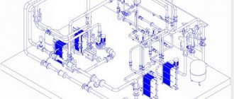
Based on the 3D model of the object presented by the designer, the technical department begins the formation of a weld pattern.
Simultaneously with drawing up the scheme, other related documents are also prepared:
- summary table of joints;
- acts of welders performing test welds and assigning them a personal mark;
- certificates of welding work.
Without a complete set of documents, the facility cannot be accepted for operation
Signature
The layout of the welded joints of the pipeline must be certified by the signatures of the following officials:
- foreman directly responsible for performing welding work at the site;
- head of production and technical department;
- Chief Engineer;
- welders who performed the work, indicating the number of their personal mark.
The completed and certified document must be agreed upon with the design organization.
It is also necessary to coordinate with it all deviations from design parameters encountered as a result of monitoring, such as dimensions and slopes. A certified record of the absence of deviations or their agreement is made on the form. If there are many deviations, they can be agreed upon in a separate act. Then the document contains a link to the number and date of this document
Pivot table
The document is drawn up according to the unified form P27.4, approved by Order of the Ministry of Energy No. 197. It must contain a complete list of seams welded at the facility.
The pivot table contains information about all connections of an object in a form convenient for control, generalization and analysis.
The following data is provided for each connection:
- serial number,
- the name of the node to which it belongs;
- type of steel alloy from which the pipes are made;
- their diameter and wall thickness;
- quantity;
- number corresponding to the designation on the Diagram.
If additional seams were welded on the site, their number and number are given in the additions column . This table allows you to determine the total number of joints, group them by diameter, wall thickness, and the need for non-destructive testing. This makes it easier to plan labor intensity, the need for consumables, as well as instrumental quality control of connections.
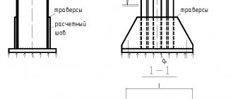
Minimum distance between welds
The distance between welds in metal structures is determined under different conditions. Below are basic examples with distance restrictions.
| Type of seams and objects near which they are located | Determining the minimum distance |
| The distance between the axes of seams that are adjacent but do not interface with each other. | Not less than the nominal thickness of the parts being welded. If the wall is more than 8 mm, then the distance should be 10 cm and above. For minimum workpiece sizes, the distance should be at least 5 cm. |
| The distance from the rounding of the bottom of the workpiece to the axis of the butt weld. | What is taken into account here is not the exact dimensions, but the possibility of subsequently carrying out control using ultrasound. |
| Welded joints in boilers. | When located in boilers, welds should not reach the supports or come into contact with them. There is also no exact data here, but the distance should allow you to monitor the condition of the boiler during operation and not interfere with quality control. |
| Distance from holes to weld. | This includes welding or flaring holes. This distance should not exceed 0.9 of the diameter of the hole itself. |
| Distance from weld to insert. | Here, on average, a distance of about 5 cm is left. If we are talking about large diameters, then it can change upward. |
| The distance between adjacent seams at the holes. | The minimum distance should be 1.4 times the diameter. |
Design rules
The pipeline welding diagram must contain the following information:
- Object name;
- pipeline class;
- pipe parameters: alloy material, diameter and wall thickness;
- transportable medium;
- snapping to reference points.
Each joint on the diagram must have its own unique number . Sometimes continuous numbering of welded joints throughout the entire project is used, then the designation takes the form “E12.123”, where before the dot there is an object identifier, and after the actual joint number on a specific diagram.
The stage of forming a diagram of welded joints from a 3D model. The drawing is simplified, fittings and equipment are replaced with symbols.
In addition, the diagram can indicate the distance between adjacent joints and supporting objects, such as turns, reinforcement, supporting metal structures or process equipment. This is mandatory in two cases:
- the pipeline is covered with a layer of insulation;
- the site runs underground or is hidden in the walls.
If necessary, markings (for example, in the event of an accident, planned repair or inspection) will help you quickly and without unnecessary costs and damage to structures find the joint in the event of repairs, without resorting to additional documentation.
Joints in a schematic drawing can be of two types:
- rotary;
- non-rotating.
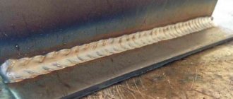
Rotary welds include welds made by a welder with a section of pipe rotated along the longitudinal axis at a certain angle . Usually this is an angle that is a multiple of 90°. Such seams are welded in the “bottom” position. Such seams are of higher quality and more durable, since the work is carried out in a position convenient for welding. Analysis of statistical data shows that the frequency of detection of defects in such seams is significantly lower than in non-rotating ones. welded joints.
A fixed joint is welded without rotating the pipe to a convenient position . On the contrary, the welder has to follow the seam around the pipeline, including in disadvantageous positions: seams with a positive and negative slope, as well as vertical and ceiling ones. In this case, it is necessary to change the inclination of the electrode, its speed, welding current and other important operating modes several times.
In this case, the seam is welded in several stages, which negatively affects its strength and durability. Working in such conditions requires a worker with extensive experience and high qualifications.
Near each joint, the details of the welders who welded it are indicated (full name, personnel number or personal mark number).
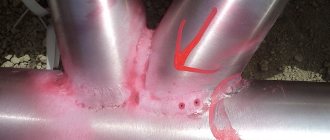
The document also notes connections for which quality control will be required by non-destructive means (ultrasound, x-ray, etc.). For particularly important objects associated with high pressures and temperatures, aggressive environments and other factors, control is carried out for all joints.
The location diagram of welded joints indicates the joints at which non-destructive testing (ultrasonic, radiographic) is required. All joints are subject to visual inspection.
When drawing up a document, the same coordinate system is used as in other design and working documentation.
Important! The schema data and the summary table must match the Work Log data in the following parameters:
- connection numbers;
- pipe parameters;
- Full name of welders and personal mark numbers
- duration of work.
If the dimensions and slopes of the constructed object correspond to the design values, the inscription is written on the diagram: “There are no deviations from the design parameters.” Otherwise, a designer's inscription coordinating these deviations or a link to a separate document - an act of approval - is required.
The diagram is included in the object passport , drawn up on high-quality media and using materials that guarantee long-term storage.
After completion of the work, all documentation is checked for completeness and correctness of execution and filling. After verification, the documents are handed over to the archive.
Technical center "WELDING"
The layout of welded joints is not to scale. Welded joints should be marked on the diagram. The distance between joints is indicated if the pipeline is subsequently insulated or underground. This is necessary to determine the location of the welded joint.
The joints in the diagram are indicated as rotary and non-rotary.
A rotary joint is a pipeline joint that is welded by rotating the pipe by 360˚, 180˚ or 90˚, and welding is usually performed in the lower position.
A rotary joint is easier to perform, since welding occurs in a comfortable position, which in turn indirectly affects the quality of welding. The likelihood of defects occurring is much less than when welding non-rotary joints.
A fixed joint is a pipeline joint, welding of which occurs without rotating the pipe, and the welder himself performs welding in various positions around the pipeline.
A fixed joint is difficult to make. The main difficulty lies in the need to weld in different positions (bottom, vertical, ceiling seam). When welding in different positions, it is necessary to adjust the current strength. Welding a fixed joint requires high skill.
Before approval at the site, the welder must weld test and approval joints. The dimensions, design and position of the trial and acceptance joints must match the standard dimensions of production welded joints.
Also on the diagram of welded joints the number of the joint is indicated. The numerator indicates the serial number of the joint. The denominator indicates the personal mark of the welder.
The welder's mark is assigned upon passing certification at the NAKS certification center. To work at hazardous production facilities, the welder’s mark is assigned by order of the enterprise , in accordance with clause 8 of the Federal Tax Code.
The welder's mark is made in accordance with GOST 25726-83. On one side of the brand there is a mirrored alphabetic and numerical designation, on the other side there is a place for impact during branding.
Depending on the object on which welding is being carried out, the mark is located at a distance of 40mm - 60mm from the welded joint. When welding is performed by several welders, marks are placed at the boundaries of the joints.
Marking of welded joints is necessary to identify the welder who made the welded joint. If defects are detected in the welded joint, the contractor is determined by the applied mark and the issue of removing the welder from work and recertifying him, with passing practical and theoretical exams, is decided.
The diagram of the location of welded joints indicates the joints at which non-destructive testing (ultrasonic, radiographic) was performed. All joints are subject to visual inspection. For each hazardous production facility, the scope of control is determined according to the relevant regulatory documents.
A summary table of welded joints, carried out on the diagram, will allow you to determine the number of joints of different diameters and the required number of non-destructive testing.
The stamp for the location of welded joints is signed by the welding supervisor, the welders who performed the welding, and the installation supervisor.
The location diagram of welded joints indicates the name of the object, the group or class of the pipeline, the diameter and thickness of the pipeline wall, the working environment, connections to fixed supports, buildings, fittings, etc.
Important!!! The layout of welded joints must correspond to the welding work log. (Numbering of joints, marks, diameters, wall thickness, welding sequence, as well as welders).
Designations of joints in the diagram
The joints in the diagram are indicated in accordance with the state standard GOST 2.312-72 “Conventional images and designations of seams of welded joints”, with a solid main line.
The following inscription is made in the form of a fraction on the take-out:
- numerator - joint number;
- denominator is the number of the welder’s personal mark.
A personal mark is issued for each welder separately . During certification, he welds a test seam that matches the material, diameter and thickness of the pipes with the actual connections on site. Such tests are carried out in special certification centers, the number of the personal mark is approved by order of the installation company.
Main types of welds and their brief characteristics
GOST describes three types of welded joints of steel pipelines and provides their symbols. This:
- Butt - “s”.
- Angular – “y”.
- Overlapping – “n”.
Within each type, the standard distinguishes various subtypes depending on different parameters. These include the diameter and thickness of the pipe being welded, the type of weld, the number of sides of the weld, the configuration for the gasket and the possibility of its removal, the presence of bevel of the edges (bevel of one or two edges), the shape of the cross-section of the edges or suture material, and the welding method.
According to GOST 16037-80, when connecting a pipeline, welding under shielding gas (argon), submerged arc and gas can be used. When working in an atmosphere of protective gases, the use of consumable and non-consumable electrodes is allowed.
To determine welding technological parameters, GOST 16037-80 recommends taking into account the following parameters (the document contains specific values depending on the type of welding):
- workpiece thickness (s);
- seam width (e);
- distance between edges (b);
- convexity (g);
- seam thickness (a);
- dulling of edge (c);
- overlap depth (B);
- fillet weld leg (K);
- pipe diameter (Dn);
- flange chamfer size (f).
All specified parameters are not relevant for all types of seams.
During the work, various types of welded joints are used depending on the specifics of the situation. For welding circular joints of pipes according to GOST, butt joints with the designation C1-C53 are used. This type of seams, in turn, can be made as one-sided or double-sided, straight and with rounded beveled edges.
Single-sided seams may include a removable or retained lining, as well as a fusible insert.
When connecting sectors at turns, the connections can be made with beveled edges and have the symbol C54-C55.
When connecting a flange to a pipeline, the designation C56 is used.
Fillet welds are prescribed in the standard as U5-U21, lap welds - H1-H4.
Sample form
All forms are filled out in accordance with the requirements of the standard. Below is a welding form for the pipeline (sample) .
The document is at the final stage of formation. Contains the necessary joint data, corner stamp and additional information. A summary table is visible above the stamp.
The diagram of welded joints is an important document that describes the relative position of the joints and their most important parameters . It is issued for any facility that has pipelines with welded seams. The diagram and the summary table compiled with it serve as a means of planning installation work, recording execution and quality control.
Documents regulating distances between welds
For each type of work, be it welding pipes, creating and strengthening metal structures, repairing and producing metal products, including work with certain materials, it is regulated by its own regulatory documents. Among the main ones are:
- ISO 139201996 is an international classification that regulates the general tolerances of welded structures;
- SNiP 2-23-81 is a guide concerning the design and strengthening of steel structures;
- SNIP 3-42-80 is a guide concerning welding, assembly and quality control of pipelines that are connected by welding.