Exact. welding
Hard modes
Hard modes provide higher performance and less power consumption. Due to the fact that the surface of the parts under the electrodes heats up relatively less under harsh conditions, the electrodes heat up less and, despite the increase in pressure, their consumption decreases. The depth2 of indentation at the welding site and warping of the product are noticeably reduced. In general, hard modes are advisable, first of all, in mass production, where the gain in productivity and energy consumption will fully compensate for the additional costs associated with the acquisition, operation and power supply of more powerful equipment.
Current strength and density.
As the thickness of the sheets being welded increases, the current strength should increase. For welding low-carbon steels of medium thickness on serial machines, the approximate selection of current strength l can be carried out according to the following relationship:
l=6500qa,
Where q is the thickness of the sheets being welded in mm.
When welding sheets of different thicknesses, the choice of parameters is made under the condition that there is sufficient heating and deformation of the thinner sheet. Therefore, in the given relationship and in subsequent ones, the value of q is related to a thinner sheet.
Current density I for hard modes is selected within the range of 120 - 360 d/Lm*, for soft modes 80 - 160 A mm2.
With increasing sheet thickness, the density is then/? decreases. When the metal of the parts being welded has increased thermal and electrical conductivity, the current density should increase. Thus, when welding aluminum or its alloys, the current density sometimes reaches 1000 A/mm2 and higher. As mentioned earlier, the current density should be selected higher when, for some reason, the pressure is assumed to be increased.
Resistance spot welding
Heating time
Like current, heating time (tcs) increases with increasing part thickness. Approximately for welding low-carbon steel at hard conditions, the heating time can be selected according to the ratio
tce — (0.1 -f-0.2) q sec.,
where q is the thickness of the thinner sheet in mm.
It is not recommended to take a shorter heating time, since random, even minor errors in the operation of the time regulator can cause serious deviations from the required heating and welding quality.
For welding sheets up to 3 mm thick in soft modes, the heating time can be selected according to the ratio.
I = (0.8×1) q sec.
Heating for too long can cause overheating of the metal in the welding zone.
For welding metals with high thermal conductivity, the welding time is assumed to be short (at high current strength); when welding hardening steels, on the contrary, in order to avoid the formation of hardening cracks during rapid cooling, the heating time often has to be increased (with a corresponding decrease in current).
Spot welding progress
Common Defects
As with any work, various spot welding defects may occur. In order to prevent various defects from arising, you need to know them and pay additional attention to the place where they may appear. The most common defects include:
- Lack of penetration of the surface partially or completely. Most often, failure to cook occurs due to low-quality electrodes, low current, or excessive compression. Most often, the defect is visible during inspection; with the help of special instruments you can understand how poor the quality of the seam is. Also, using the device, you can determine the presence of unwelded areas even in a visually normal seam.
- Cracks. These are quite common defects that appear due to the use of high current or uncleaned parts.
- Tears at the edges. This defect is not very common, but can also occur. When calculating where the welding point will be, it is necessary to take into account the distance that will be enough to create a high-quality seam. For materials of different thicknesses this distance will be different.
- Internal splash. Such a defect cannot always be noticed immediately after cooking is completed. The defect is formed due to the fact that the liquid material leaves the core during cooking, causing a gap to appear between the parts. The main reason why such a defect occurs is the application of a long pulse at a high current, which leads to excessive melting of the core. If this is due to the fact that the device is completely new, then it is worth trying to make several points on a different material to adjust the tool.
- External splashes. A fairly obvious defect that appears due to poor clamping of metal parts. Due to the lack of forging torque, there is no possibility to connect the workpieces and the molten mass appears on the outside of the metal element.
- Dents appear. Excessive compression of the workpiece or the use of small-diameter electrodes leads to the appearance of dents. Also, due to these factors, the melting zone may increase, which leads to the occurrence of defects in the finished seam.
- Burn. This is the most common defect. There may be several reasons for the appearance of this defect, but most often the burn appears due to contaminated surfaces of the parts being welded or the tip of the conductor.
Pressure
The choice of pressure (P) is made depending on the thickness, condition and material of the workpieces, as well as on the nature of the adopted heating mode.
For welding low-carbon steel, the pressure depending on the thickness is selected according to the formula
P=(60×200)q kg.
where q is the thickness in mm.
The specific pressure has a limit of 3x10 kg/mm2.
Mild hot-rolled steel can be coupled at lower pressures. Cold-rolled steel, which has received increased work hardening, requires a slight increase in pressure (by 20-30%). When the workpieces are poorly straightened and have warping, then before tightly squeezing the sheets in the Siamese area, it is necessary to straighten them under the electrodes. The total force required in this case must be increased, especially for larger thicknesses. So, for sheets with a thickness of 3-6 mm, this additional force alone is 100-400 ke. For the same reason, the force should also increase when the points are located in those places of the welded unit where squeezing the sheets is difficult (near the ribs and other stiffeners, and at the places where the parts meet at a radius, etc.).
The specific pressure increases with the strength of the metal being welded. When welding low-alloy steels, it can be 120-160% of the specific pressure for low-carbon steel; when welding austenitic and heat-resistant steels and alloys, it increases by 2-3 times.
- Electrode diameter. The electrode diameter (d) determines the current density, specific pressure and degree of cooling intensity of the surface of the part.
- The diameter of the electrode has a relatively small effect on the electrical resistance of the welding zone, only at the final stage of heating, when complete contact of the surfaces of the electrode and the part is achieved.
- Therefore, during prolonged heating, the influence of the electrode diameter is more pronounced. The diameter of the electrode increases with the thickness of the parts.
- For thicknesses up to 3 mm, the diameter of the electrode is calculated using the following formula:
D=2q+3mm,
where q is the thickness of the thinner sheet.
For parts with greater thickness, the calculation is carried out using the formula
Changing the diameter of the electrode is often used to equalize the heat when welding parts that are unequal in thickness or type of metal.
During the welding process, under the influence of strong heat and heavy mechanical load, the working part of the electrode changes with the formation of a mushroom-shaped thickening, and the surface becomes contaminated with metal oxides. An increase in the actual diameter of the electrode at constant current and compression force means a decrease in current density and specific pressure. As a result, the heating intensity in the welding contact is greatly reduced, and metal compaction becomes more difficult and welding may be of poor quality. In addition, contamination of the surface of the electrodes can cause an increase in contact resistance, overheating and even melting of the surface of the sheets. It is generally believed that wear-related increases in diameter by more than 10% are no longer acceptable. Such electrodes must be cleaned with a file, a special device, or sharpened.
Basic physical parameters for resistance welding
The main parameters of contact welding modes are the current strength, the duration of the flow and the force with which the parts being connected are compressed:
- Welding current strength . Measurements of this parameter are carried out in Amperes or kilo-Amps, measurements are made using special instruments.
- Compression force for welded parts . Measured in decaNewtons. Measurements are also made using special equipment.
- Duration of welding current flow . It is measured in seconds and is timed.
- In rare cases, forging force may also be applied to compact the weld core..
Results
The use of resistance welding from an inverter with your own hands allows you to connect metals and alloys of different grades using a high temperature electric current, which provokes plastic deformation of the contact zone of parts when they are compressed.
Resistance welding technology has a wide range of applications: it is actively used in everyday life and on an industrial scale in the manufacture of large batches of the same type of metal products.
It is important to follow the technology, put the resistance welding designation on the diagram, use the electrodes recommended by the manufacturer, select the correct operating modes of the unit, then the welds will acquire high quality and durability.
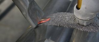
Technological process
The spot welding process is carried out in the following stages:
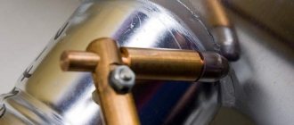
- The elements to be welded are overlapped.
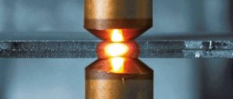
- At the point of future connection, the elements are clamped between two electrodes . These electrodes, when connected to a transformer, conduct current to the welding site.
- With the supply of current, the parts being welded are heated at a point that is sandwiched between the electrodes.
- It is necessary to wait until the inner layers of the metal reach plasticity.
- After turning off the current, you need to apply pressure to the electrodes for some time . This is done so that the molten metal crystallizes normally.
After carrying out the work at the welding site, you can see the cast point of the welded joint.
Advantages and disadvantages
The advantages of welding using this method include:
- a fairly “clean” cooking method;
- there is no need to use additional components in the form of flux gases and others;
- absence of various wastes and slags;
- since welding occurs without the use of gas, no harmful substances are released and the welder is more protected in this matter;
- spot welding has high efficiency;
- if it is necessary to perform a large number of works, it is possible to use various automated units;
- high quality joints in a very short period of time.
If all norms and standards are observed when performing spot welding, you can obtain a high-quality seam that will be extremely neat and reliable.
Disadvantages of spot welding:
- difficult to implement bonding when welding different metals;
- if the pulse supply is exceeded, metal splashing is possible;
- design complexity when cooking several points simultaneously;
- complication of the design of electrodes and their use in multi-point welding.
Areas of application
In production, such welding is used to connect workpieces of different and equal thickness: these can be intersecting rods, steel sheets, non-ferrous alloys, I-beams, angles and other profile workpieces. This method is effective when welding automobile and tractor parts and railway cars.
Spot welding has also been used at home. Using purchased or homemade welding machines, they repair electrical cables, microelectronic parts, household appliances and much more.
The role of plastic deformation
Plastic deformation of the metal is caused by both external factors - force from the electrodes, and internal ones - stresses that arise during the unfree expansion of the metal in the welding zone. In spot, seam, projection and resistance butt welding, plastic deformation of the metal is present throughout the entire welding process: from the formation of cold contact to forging the joint. In flash welding, deformation occurs during the preheating and upsetting stages.
The main role of plastic deformation during spot, seam and projection welding is the formation of electrical contact, the formation of a plastic belt to keep the molten metal from splashing out and limit the spread of welding current in the internal contact, and to compact the metal at the cooling stage.
The primary role of plastic deformation in butt welding is to remove oxides to form metallic bonds at the joint (the second stage of the welding cycle) and electrical contacts (primarily during the first heating stage). Deformation is caused by the compression force generated by the welding machine drive. To form the initial electrical contact, a small pressure is sufficient, at which microplastic deformation of the surface topography of the ends occurs. To remove oxides and form bonds, a relatively large volumetric plastic deformation of the parts is required. In most cases, butt welding uses a free volumetric deformation scheme, in which the metal flows without any external restriction. In the butt welding process, the amount of deformation is judged by the shortening of parts caused by upsetting.
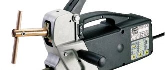
Spot welding machine
There are a variety of spot welding devices, but all welding machines have a similar design. Regardless of what the device is intended for, the basic design elements will be almost the same.
A simple device may not have a power regulator. In this case, the master independently regulates the compression force and duration of impact on the metal. It is very important to monitor the condition of the electrodes during the process.
Many craftsmen use homemade spot welding, which is completed in just 20-30 minutes. Thanks to its simple design, you can make the device yourself.
The main part of a homemade device is a transformer. Most often, craftsmen use a transformer from a microwave oven. The type of transformer is not so important, the main thing is power. The optimal parameter is 0.9-1 kW. The transformer will only need a magnetic core and a primary winding, so all unnecessary parts can be knocked out or picked out using any available methods.
You will need to make the secondary winding yourself. To do this, take a copper wire of greater thickness, the diameter of which is at least 1 cm. After modification, the device can output up to 1000A, which will allow high-quality welding of thin metal sheets. To increase the power of the unit, you can combine several transformers of the same type into one.
Application of technology in practice
Electric spot welding allows you to create a permanent connection between the edges of metal parts using high temperature from the passing electric current from the inverter and plastic deformation of their contact zone during compression.
It provides the welder with a unique opportunity to work with a wide range of welded thicknesses: from 1-2 micrometers to 30 millimeters.
An extremely important role in this method of performing welding operations is assigned to the electrical resistance of the joint zone, which is why it is also called electric resistance welding. The rules for carrying out welding operations using the contact method are described by state standards 15878-79.
Contact welding technology.
The advantages of using spot welding technology are very wide.
Let us describe the most significant of them:
- making connections between metal parts requires an extremely short period of time;
- technology allows operations with high power consumption;
- the welding process can be automated, which makes it possible to integrate welding units for resistance welding into production lines at large enterprises;
- welds created by this method are distinguished by high performance parameters, regardless of the skill level of the craftsman;
- during operation, no special materials or special components are required: filler welding wire, flux, shielding gas, etc.;
- electrodes for point technology are affordable and can be found in many specialized stores.
In addition to spot welding, other types of resistance welding are characterized by a large list of advantages: butt welding, seam welding, etc. But it is spot welding that is most common today.
It is relevant in the manufacture of large-sized building structures, space units, miniature semiconductor devices, and microcircuits. This state of affairs is explained by the universality of the contact method of welding metal parts.
Almost all structural materials known to mankind can be combined using this technology into a single product: various types of low-carbon, alloy steel, heat-resistant, corrosion-resistant alloys, alloys of aluminum with other metals, magnesium and titanium, etc.
Do-it-yourself spot welding is also relevant for performing repair operations in small workshops, service stations, etc. With its help, cars, railway cars, airplanes are assembled, reinforced concrete structures are erected, and radio-electronic units are created.