Drilling, countersinking and reaming
TO
category:
Drilling metal
Drilling, countersinking and reaming
Next: Metal Milling
Drilling, countersinking and reaming are carried out on various types of drilling machines, aggregate boring machines, as well as turning machines. In addition, these operations can be performed using hand and mechanical drills.
Drilling. Drilling is a machining operation to produce holes in a solid material. Drills of various designs are used as cutting tools for drilling. The main movement when drilling is rotational, the feed movement is translational. On general purpose drilling machines and boring machines, the main movement is the drill; on lathes and special drilling machines for deep drilling, the drill has only translational motion, and the workpiece has rotational motion; this determines higher processing accuracy.
Rice. 1. Twist drill
During drill operation, the transverse edge does not cut, but presses the metal of the workpiece. It was found that about 65% of the feed force occurs at the transverse edge.
Rice. 2. Double sharpening of twist drill
To facilitate the working conditions of the drill, the transverse edge is sharpened. For the same purpose, drills working on cast iron and steel are double sharpened with an angle of 2 ft! = 75-80°. The width b of the rear surface of the second sharpening is made within 0.18-0.22 of the drill diameter. As a result of double sharpening, the width of the chip increases at the expense of the thickness, the leading angle decreases, and therefore the durability of the drill increases.
Centering drills are used for drilling center holes when centering workpieces. These drills are made combined and double-sided for better use of tool steel.
Feather drills are made in the form of blades. They are rarely used, mainly when drilling holes in hard forgings and castings.
Drills with carbide inserts are manufactured with a diameter of 3 to 50 mm and are used for drilling bleached cast iron, hard steels, etc.
Deep holes are defined as holes having a length five times or more greater than their diameter.
Drills for deep drilling are manufactured with a diameter of 6 to 100 mm. Drilling holes with such drills is carried out on special drilling machines, and in most cases, only the feed movement is communicated to the drill, and the main movement (rotational) is transmitted to the workpiece.
Rice. 3. Center drill
Rice. 4. Feather drill
Rice. 5. Drill with carbide insert
In Fig. 6 shows a gun drill made from a round rod. The cutting edge of the drill is formed by the front surface and the rear surface (unilateral cutting).
Rice. 6. Gun drill
Rice. 7. Gun drill
Rice. 8. Countersinking scheme
In addition to gun drills, the following are used for drilling deep holes: a) gun drills for drilling holes of small diameter and great depth. These drills are hollow inside (to supply coolant) and have a groove to drain the liquid along with the chips; b) single- and double-cut drills for drilling deep holes of medium and large diameters; c) heads for circular drilling of deep holes of large diameter. Qi.nozny drilling of metal with diameters over 100 mm is unprofitable, therefore, in such cases, hollow drilling heads with cutters fixed in them are used.
Countersinking. Countersinking is a machining operation by cutting the walls or inlet of a hole; countersinking is carried out using holes obtained during casting or forging (black) or pre-drilled holes. The purpose of countersinking is to obtain more accurate dimensions of holes and the position of their axes, shaped processing of the end (input) part of the hole to obtain recesses for screw heads, etc.
The cutting process during countersinking is similar to the simultaneous operation of several boring cutters, which in this case can be considered countersink teeth.
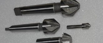
There are four main types of countersinks: for expanding holes, for producing cylindrical recesses of holes, for producing conical recesses for holes, for cleaning end surfaces.
Countersinks for expanding holes are made three-pronged (for holes up to 30 mm) and four-pronged (for holes up to 100 mm). In Fig. 9, a shows a three-tooth countersink with a conical shank for mounting in the machine spindle, and in Fig. 281, b - four-tooth mounted countersink. In order to increase productivity, countersinks are equipped with plates made of hard alloys.
In addition to solid countersinks, countersinks with inserted knives made of high-speed steel or reinforced carbide alloys are also produced. The advantage of such countersinks is the saving of high-speed steel and the ability to regulate the processing diameter. Mounted countersinks with insert knives can have 6 teeth -
Processing with countersinks ensures correction of the axis with holes, increases accuracy to 4-5 classes and surface cleanliness to 4-6 classes:
Countersinks for producing cylindrical recesses (Fig. 281, c) have a guide pin, which is manufactured integrally with the countersink body or (in other designs) made replaceable.
Countersinks for producing conical recesses - countersinks (Fig. 281, d) - most often have an angle 2cf> = 60o, less often 75, 90 and 120°. The number of teeth in countersinks ranges from 6 to 12.
Countersinks for cleaning end surfaces (Fig. 281, d) have teeth only at the end. The number of teeth of these countersinks, depending on their diameter, can be 2, 4 or 6.
In addition to those described, there are also combined countersinks for producing stepped holes. These countersinks allow complex processing to be carried out on a simple machine, thereby reducing the cost of processing.
Rice. 9. Countersinks
Deployment. Reaming is a machining operation that involves cutting the walls of holes in order to obtain high precision and surface finish. When unfolding, a layer of metal of a few tenths of a millimeter is removed from the walls of pre-processed holes (by drilling and countersinking or just drilling); holes are obtained within the 1-3 accuracy classes and 6-9 cleanliness classes. To obtain accurate and clean holes, sequential rough and finishing reaming is used.
Rice. 10. Sweeps
According to the shape of the hole being machined, reamers are divided into cylindrical and conical.
Reamers, just like countersinks, are made with tail and attachment ones.
The working part 1 of the cylindrical reamer consists of a cutting part 2 of the calibrating part and a rear cone. The number of reamer teeth is taken even (six or more) to achieve an accurate measurement of the reamer diameter. To avoid obtaining a faceted hole, the distribution of teeth around the circumference is made uneven, but taking into account that it is possible to measure the diameter along the tape (variation in steps of 1-4°).
According to the method of application, reamers are divided into machine and manual; by design - solid and prefabricated with insert knives. To increase durability, the cutting part of the teeth is reinforced with hard alloy plates.
Hole making: types of operations and tools used
Hole processing is a whole series of technological operations, the purpose of which is to bring the geometric parameters, as well as the degree of roughness of the inner surface of pre-made holes, to the required values.
The holes that are processed using such technological operations can be previously obtained in solid material not only by drilling, but also by casting, punching and other methods. Processing a drilled hole with a cylindrical countersink
The specific method and tool for processing holes are selected in accordance with the characteristics of the desired result. There are three methods for processing holes - drilling, reaming and countersinking. In turn, these methods are divided into additional technological operations, which include drilling, counterboring and countersinking.
To understand the features of each of the above methods, it is worth considering them in more detail.
Drilling And Reaming Holes
The most common method of making holes in solid material is drilling. The cutting movement during drilling is rotational, the feed movement is translational. Before starting work, check the coincidence of the vertices of the front and rear centers of the machine. The workpiece is installed in the chuck and inspected so that its runout (eccentricity) relative to the axis of rotation does not exceed the allowance removed during external turning. They also inspect the runout of the end of the workpiece in which the hole will be machined, and align the workpiece along the end. It is possible to ensure the perpendicularity of the end to the axis of rotation by trimming; at the same time, a recess is made in the center of the workpiece for the appropriate direction of the drill and to prevent its withdrawal and breakage.
Drilling
To process holes, they must first be obtained, for which various technologies can be used. The most common of these technologies is drilling, performed using a cutting tool called a drill.
Main parts of a twist drill
Using drills installed in special devices or equipment, both through and blind holes can be produced in solid material. Depending on the devices and equipment used, drilling can be:
- manual, performed using mechanical drilling devices or electric and pneumatic drills;
- machine tools, carried out using specialized drilling equipment.
The physics of drilling holes
The use of manual drilling devices is advisable in cases where holes, the diameter of which does not exceed 12 mm, need to be obtained in workpieces made of materials of small and medium hardness. Such materials include, in particular:
- structural steels;
- non-ferrous metals and alloys;
- alloys made of polymer materials.
If it is necessary to make a hole of a larger diameter in the workpiece, and also to achieve high productivity of this process, it is best to use special drilling machines, which can be desktop or stationary. The latter, in turn, are divided into vertical and radial drilling.
Reaming, a type of drilling operation, is performed in order to increase the diameter of a hole previously made in a workpiece. Drilling is also performed using drills whose diameter corresponds to the required characteristics of the finished hole.
The physics of drilling holes
This method of processing holes is undesirable for those that were created by casting or through plastic deformation of the material. This is due to the fact that sections of their inner surface are characterized by different hardness, which causes uneven distribution of loads on the drill axis and, accordingly, leads to its displacement. The formation of a layer of scale on the inner surface of a hole created by casting, as well as the concentration of internal stresses in the structure of a part made by forging or stamping, can cause the drill not only to move from the required trajectory when drilling such workpieces, but also to break.
When performing drilling and reaming, it is possible to obtain surfaces whose roughness will reach Rz 80, while the accuracy of the parameters of the hole being formed will correspond to the tenth grade.
Drilling technology
The process involves sequential removal of a layer of metal in a circle of a given diameter using a cutting tool. Drilling metal combines two types of motion - rotational and translational. To obtain the required hole dimensions in metal workpieces, it is necessary to accurately maintain the following technological process parameters:
- cutting tool rotation speed;
- speed of horizontal or vertical movement (depending on the relative position of the workpiece and drill).
A hole in the metal is obtained with the specified parameters only if the preparatory and main operations are correctly performed, as well as the selection of the necessary equipment and cutting tools. Pre-drilling is often performed to obtain the required accuracy. It's called draft. The operation is performed with a reduced accuracy class. Next, the finishing operation is carried out using high-precision machines and tools for metal workpieces.
In all cases, different types of drills are used to obtain the required hole. On drilling machines, a chuck with a fixed drill rotates and is brought to the surface of the workpiece. On metal-cutting machines, the drill is fixed in the tailstock of the machine, and the workpiece rotates. The second method allows you to obtain higher accuracy of the hole and the walls of the resulting hole.
Depending on the tasks, the following types of drills are used for both methods:
- spiral (the most common type of this tool);
- with soldered plates on the cutting edge;
- centering;
- cannon;
- feather (used for drilling holes in workpieces made of any type of wood).
Twist drills with their transverse edge exert pressure on the surface of the metal. This process accounts for more than 65% of the force during rotational and translational motion. At this moment, there is a significant increase in temperature of both the surface of the workpiece and the leading edge of the drill. Therefore, it is necessary to properly observe the thermal regime during the drilling process.
To speed up the cutting process in twist drills, so-called double sharpening is used. It allows you to work more efficiently on the hardest grades of metal, including cast iron. Such sharpening leads to an increase in chip width, the main angle decreases, and the durability and durability of the drill increases.
The technology for creating centering holes involves the use of special centering drills. They are made of tool steel and have a double-sided combined design.
Applying plates with increased strength to the cutting edge of the drill allows them to be used for drilling products made of cast iron, metal of increased hardness, dense building structures (concrete, stone, ceramic granite, etc.).
Feather drills differ in the design of the cutting edge. It is made in the form of plates. They are usually used to make holes in wood pieces. Sometimes special point drills are used to make holes in solid forgings and some types of castings.
Countersinking
With the help of countersinking, performed using a special cutting tool, the following tasks related to the processing of holes produced by casting, stamping, forging or through other technological operations are solved:
- bringing the shape and geometric parameters of the existing hole into accordance with the required values;
- increasing the accuracy of the parameters of a pre-drilled hole up to the eighth grade;
- processing of cylindrical holes to reduce the degree of roughness of their internal surface, which, when using such a technological operation, can reach a value of Ra 1.25.
When countersinking, less cutting force is applied than when drilling, and the hole is more accurate in shape and size
If it is necessary to subject a hole of small diameter to such processing, it can be performed on tabletop drilling machines. Countersinking of large diameter holes, as well as processing of deep holes, is carried out using stationary equipment installed on a special foundation.
Manual drilling equipment is not used for countersinking, since its technical characteristics do not provide the required accuracy and surface roughness of the hole being machined. Varieties of countersinking are technological operations such as counterbore and countersinking, which use various tools to process holes.
Conical countersinks for metal
Experts give the following recommendations for those who plan to perform countersinking.
- Countersinking should be carried out during the same installation of the part on the machine in which the hole was drilled, and only the type of tool used changes from the processing parameters.
- In cases where an unprocessed hole in body-type parts is subjected to countersinking, it is necessary to control the reliability of their fixation on the machine table.
- When choosing the amount of allowance for countersinking, you need to focus on special tables.
- The modes in which countersinking is performed must be the same as when drilling.
- When countersinking, the same occupational health and safety rules must be observed as when drilling on plumbing equipment.
Drilling according to markings
Rice. 1. Drilling holes according to the markings:
a – marking and punching the center of the hole; b – marking and punching of the control circle; c – moving the drill away from the center of the hole; d – correction of the drill direction; 1 – mark from the center punch; 2 – groove from a pre-drilled hole; 3 – machined hole
This type of processing of workpieces is carried out in several stages:
- preliminary.
- final.
When pre-drilling, drill a small hole (0.25d). Next, the spindle with the drill is retracted to check the prepared hole with the original markings.
If the result of preliminary drilling is satisfactory (Fig. 1, b), final processing is carried out, for which work continues until the cutting tool leaves the part. If a bevel occurs and the hole being drilled goes away (Fig. 1, c), an adjustment is made using a cross-section tool - grooves are cut in the direction where the hole needs to be moved (Fig. 1, d). Thanks to the guides for the drill, the direction is set in the desired direction to correct the bevel.
Countersinking and countersinking
When performing countersinking, a special tool is used - a countersink. In this case, only the upper part of the hole is processed. This technological operation is used in cases where in this part of the hole it is necessary to form a recess for the heads of fasteners or simply chamfer it.
What is the difference between countersinking and countersinking?
When performing countersinking, certain rules are also followed.
- This operation is performed only after the hole in the part is completely drilled.
- Drilling and countersinking are performed in one installation of the part on the machine.
- For countersinking, set low spindle speeds (no more than 100 rpm) and use manual tool feed.
- In cases where countersinking is carried out with a cylindrical tool whose trunnion diameter is greater than the diameter of the hole being machined, the work is performed in the following sequence: first, a hole is drilled, the diameter of which is equal to the diameter of the trunnion, countersinking is performed, then the main hole is drilled to a given size.
The purpose of this type of processing, such as counterbore, is to clean the surfaces of the part that will come into contact with nuts, bolt heads, washers and retaining rings. This operation is also performed on machines and using a counterbore, for installation of which mandrels are used on the equipment.
Types of work performed on drilling machines
Drilling machines perform drilling, reaming, countersinking, reaming, countersinking, counterbore, processing stepped holes and cutting internal threads. By drilling (Fig. 16, a) through and blind holes are obtained. By drilling (Fig. 16, b) the diameter of the previously drilled hole is increased.
Countersinking (Fig. 16, c) also increases the diameter of the hole, but compared to drilling, countersinking allows for greater accuracy and processing productivity.
Countersinking can be used to process holes made in a workpiece by casting or pressure. Reaming (Fig. 16, d) is a finishing operation that ensures high hole accuracy. Reaming is used to process cylindrical and conical holes after countersinking or boring. Countersinking (Fig. 16, e, f) processes cylindrical and conical recesses for the heads of bolts and screws. To ensure perpendicularity and alignment of the machined surface to the main hole, the cutting tool (countersink) is equipped with a guide cylinder (Fig. 16, e).
Countering (Fig. 16, g, h) is used to process the end support planes for the heads of bolts, screws and nuts. The perpendicularity of the machined end surface to the main hole is ensured by the guide cylinder of the cutting tool (counterbore). Using a centering drill (Fig. 16, i) the center base holes in the shafts are processed. Internal threads are processed with taps (Fig. 16, j). In this case, the feed speed must be equal to the thread pitch (So = h). Complex surfaces are processed with a combined tool (Fig. 16, l).
Rice. 16. Schemes for surface treatment on drilling machines: a – drilling; b – drilling; c – countersinking; d – deployment; d, f – countersinking; g, h – countersinking; and – processing of basic center holes; k – cutting internal threads; l – processing of complex surfaces
Rice. 17. Processing of precise conical holes: a – countersinking with a stepped countersink; b – rough deployment; c – final deployment
The processing scheme for a precise conical hole is as follows: drilling a cylindrical hole; countersinking with a stepped conical countersink (Fig. 17, a); reaming with a conical reamer with chip separating grooves (Fig. 17, b); deployment with a smooth conical reamer (Fig. 17, c).
Deployment
The reaming procedure involves holes that were previously drilled into the part. An element processed using such a technological operation can have accuracy up to the sixth grade, as well as low roughness - up to Ra 0.63. Reamers are divided into rough and finishing, and they can also be manual or machine.
Cylindrical manual reamers 24Н8 0150
The recommendations that should be followed when performing this type of processing are as follows.
- Allowances in the diameter of the hole being machined are selected according to special tables.
- When using a hand tool that is rotated only clockwise, first perform rough reaming and then finish reaming.
- Steel parts are processed with the obligatory use of coolant, while cast iron parts are processed dry.
- Machine reaming is carried out immediately after drilling on the machine - with one installation of the part.
- To control the quality of the result, special calibers are used.
What you need to know about drilling holes in metal
You can secure a metal sheet or part using a variety of fasteners. However, you need to make holes for them. Drilling holes in metal requires a person to use special tools. To carry out the work without difficulty, you need to be able to choose equipment and work with workpieces of different sizes.
Drilling holes in metal
Equipment types
Drilling begins with preparing tools for work. You can make holes using a screwdriver, drill or a special drilling machine.
To make a hole, you need to select the appropriate equipment. For metal workpieces, you need to choose specialized equipment that is suitable specifically for this material. This is due to the fact that equipment for wood, concrete or ceramic tiles have different sharpening and shape. Tooling for metal products is marked with the letters HSS.
The working part of the tool is coated with titanium nitride coating, which increases their strength and wear resistance. For hard steels, a different tooling is used, which is designated P18. The strength of the tool increases when cobalt is added to its composition. An example of marking is P6M5K5.
To drill alloy steel, drills with a tip made of carbide are used. With their help, you can drill any metal workpieces, however, due to the high price, this is not cost-effective.
When the hole is made, you can select a drill for the thread. Its diameter will depend on the previously used equipment. To make holes of different diameters in thin metal sheets, you can use cone drills.
Is it possible to drill with a drill in concrete?
Situations often arise when it is difficult to find a tool for drilling metal products at a construction site, but there is equipment for working with concrete. You cannot make holes of large diameter or in thick metal sheets with concrete drills. Otherwise, you may break the equipment or damage the surface being processed.
How to drill with a step drill?
On sale you can find stepped structures for creating holes in metal of various diameters. Several drills of different diameters are fixed on one axis. They are designed to create holes of various sizes in thin sheet metal. When working, do not rush or put too much pressure on the drill handle.
Is it possible to drill with a Pobedit drill?
Any master of finishing work will tell you that drilling metal with Pobedit equipment is unacceptable. Pobedite drills are designed for hard and, at the same time, brittle materials. These include natural stone, brick, concrete. When it hits metal, the drill will hit the surface and damage it, but there will be no hole.
Pobedit drills
How to drill large diameter holes?
Drilling large holes in metal requires the use of appropriate equipment. You can do the work in several ways:
- Crown for metal surfaces. It is a circle of the required diameter with sharpened edges. There is a drill in the center that pierces the metal. Next, at low engine speeds, the bit makes a hole of the selected diameter. During work, it is necessary to use forced cooling of the sharp edges of the crown and the surface being treated.
- Multi-stage operation. This implies the use of several metal drills of different diameters. Work begins with equipment of the smallest diameter and increases as drilling progresses.
- Cone-shaped equipment (stepped). Designed for working with thin sheet metal.
Builders recommend using crowns. However, when working with them, it is necessary not to increase the speed and ensure that all the teeth running around the circumference are intact.
How to avoid dulling a tool?
The tool becomes dull because it overheats during use. To maintain sharpness, drilling should be done at low speed. There is no need to press the power button all the way down. When drilling thick workpieces, you need to use coolants or pastes.
If there is no cooling lubricant, machine oil can be used instead. Coolant keeps the tool from overheating and reduces friction.
How to drill metal correctly?
When you turn on the tool, the drill may slide to the side, which makes it difficult to make a hole in the selected location. You can cope with this problem using a core. It is a metal cylinder with a sharp point at one end. It is necessary to attach the sharp end to the marking and hit the back side of the core with a hammer. There will be a notch on the metal through which a hole is drilled.
Drilling thick workpieces
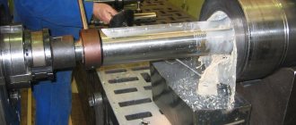
Not many novice craftsmen know how to drill a hole in thick metal. Deep drilling is more difficult than usual. In production, it is carried out using lathes. In them, the workpiece is fixed in a movable spindle, which rotates it.
If it is not possible to use industrial equipment, you can drill a deep hole using a drill. To do this, you need to purchase special guides for power tools. Additionally, it is necessary to use machine oil for cooling. During operation, you need to stop periodically to clean out the chips and allow it to cool.
How to drill with a drill?
Drilling metal with a drill requires following some recommendations:
- To make a hole you will need an electric drill, a core punch, a hammer, machine oil and safety glasses.
- Initially make markings.
- Wear safety glasses.
- When the pressure on the drill is low, you need to select the low speed position and start working.
- Don’t forget to water the area being treated with coolant.
If you follow the technology and use high-quality tools, you can make holes of different diameters and depths. To drill straight holes or accurately select the depth, you can use a device called a “depth stop.” It is attached to an electric drill and adjusted to the desired depth.
Drilling metal with a drill
How to drill with a screwdriver?
You can drill metal workpieces not only using industrial equipment or an electric drill, but also using a cordless screwdriver. This power tool is low power. Because of this, it is suitable for drilling holes of small diameter and depth.
Drilling is performed using industrial equipment and power tools. It is important to choose the right equipment and take into account the depth and diameter of the hole. To ensure that your equipment lasts longer, you should use coolant. You need to drill perpendicularly to avoid damage to the workpiece or tool.
Subscribe to the channel, like, repost, and we will post useful information about metals for you! You can also visit our website, where you will find a lot of information about metals, alloys and their processing.
"Drilling, countersinking, countersinking and reaming of holes"
In the work of a mechanic in the manufacture, repair or assembly of parts of mechanisms and machines, there is often a need to obtain a wide variety of holes in these parts. To do this, the operations of drilling, countersinking, countersinking and reaming holes are performed.
The essence of these operations is that the cutting process (removal of a layer of material) is carried out by rotational and translational movements of the cutting tool (drill, countersink, etc.) relative to its axis. These movements are created using manual (rotary, drill) or mechanized (electric drill) devices, as well as machine tools (drilling, lathe, etc.).
Drilling is one of the types of making and processing holes by cutting using a special tool - a drill.
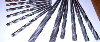
Like any other cutting tool, the drill works on the wedge principle. According to their design and purpose, drills are divided into feather, spiral, centering, etc. In modern production, mainly spiral drills and, less often, special types of drills are used.
There are 2 helical grooves on the guide part, through which chips are discharged during the drilling process. The direction of helical grooves is usually right. Left-handed drills are used very rarely. Narrow stripes on the cylindrical part of the drill are called ribbons. They serve to reduce friction between the drill and the walls of the hole (drills with a diameter of 0.25–0.5 mm are made without bands).
The cutting part of the drill is formed by 2 edges located at a certain angle to each other (apex angle). The size of the angle depends on the properties of the material being processed. For steel and cast iron of medium hardness it is 116–118°.
The shank serves to secure the drill in the machine spindle or drill chuck and can be conical or cylindrical. The conical shank has a tab at the end, which serves as a stop when pushing the drill out of the socket.
The drill neck connects the working part and the shank and serves to release the abrasive wheel during the grinding process of the drill during its manufacture. The drill brand is usually marked on the neck.
Drills are made mainly from high-speed steel or hard sintered alloys of the VK6, VK8 and T15K6 brands. Only the working (cutting) part of the tool is made from such alloys.
Basic metalworking operations
4.1 Marking
is the process of applying points and lines (marks) to the workpiece being processed, defining the contours of the parts and the processing location. The essence of marking is to draw life-size axial and control lines, hole centers, etc. on the metal workpiece.
The drawing itself is carried out using geometric construction methods and has much in common with mechanical engineering drawing, but with the difference that instead of drawing tools, special marking tools are used when marking, and the drawing itself is applied not to paper, but directly to the workpiece. Depending on the nature and shape of the product, markings can be planar or spatial.
When marking planarly, lines are applied on the surface of flat workpieces, on strip or sheet material, or on individual planes of volumetric parts, if it is not necessary to link the marked planes to each other.
With spatial (volumetric) marking, lines are applied to two or three separate surfaces of the part, located in different planes and at different angles to each other and linked to each other.
Examples of planar markings include markings in the manufacture of calipers, bore gauges, wrenches, etc., and spatial markings include markings in the manufacture of nuts, hammers, levers, etc.
The markings are applied using a scriber, caliper, height gauge, or ruler.
4.2 Chopping
is called a metalworking operation in which hard crust, scale, irregularities and roughness are removed from the surface of workpieces; cutting off edges and burrs, cutting sheet and grade material into pieces; cutting out holes in sheet material according to markings; cutting out keyways, lubrication grooves, etc.
Chopping is a crude plumbing operation; The accuracy of processing the surfaces of a part when cutting usually does not exceed 0.5 - 1.0 mm, but even such accuracy is achieved with extensive experience.
Depending on the purpose of the workpiece, cutting can be finishing or roughing. In the first case, a chisel removes a layer of metal with a thickness of 0.5 to 1 mm in one working stroke, in the second - from 1.5 to 2 mm.
The processing accuracy achieved when cutting is 0.4...1mm.
When cutting metals, a chisel and cross-cutting tool are used as cutting tools, and metalworking hammers are used as impact tools.
A chisel or crosspiece, held with the left hand, is placed at the place where the excess layer of metal is to be cut off, and a blow is struck on the head of the chisel with a hammer. A bench chisel is a hand-held cutting tool.
On the workpiece, a distinction is made between the machined and machined surfaces, as well as the cutting surface. The processed surface is the surface from which the layer of material will be removed, and the processed surface is the surface from which the chips are removed. The surface along which chips flow during cutting is called the front surface, and the opposite surface is called the back surface.
4.3 Editing (straightening)
- is a metalworking operation in which deformed, warped metal blanks or parts are given the correct flat shape. Editing is used after cutting sheet material with scissors, chopping with a chisel and other operations. Straightening is also used to straighten strip and rod material, pipes and wire. Cast iron parts are not straightened, since cast iron is too brittle and can crack during straightening.
In metalworking and especially in toolmaking, the correction of bent and warped products with great accuracy (up to tenths of a millimeter), after mechanical or heat treatment, is often called straightening the product.
Editing can be manual or machine.
When manually straightening sheet blanks and parts, steel or cast iron leveling plates or anvils, steel hammers weighing 400 - 600 g, copper, lead, brass, wooden, bakelite, etc. hammers are used.
Machine leveling is carried out on manual and driven three-rollers, on driven pneumatic hammers and on presses. This manual covers only manual editing used in training workshops.
Straightening is carried out by striking with steel hammers or hammers made of soft material in certain places, proportioning the force of the blows to the size of the convexity and the thickness of the straightened product. The surface of the leveling plate, as well as the hammer heads, must be even, smooth and well ground. When manually straightening, it is more convenient to use hammers with. round, and not with a square striker, since incorrect blows or distortions of a hammer with a square striker may leave notches or even holes on the surface of the sheet. The hammer head should lie flat on the sheet, without distortion. The hammer should be held by the end of the handle and only the hand should be used to strike.
Techniques for editing sheet material are as follows. Having laid the deformed sheet on the slab with the bulges up, if possible, trace the bulges with a graphite pencil or chalk. After this, frequent but not strong blows are applied along the straight edges of the sheet towards the convexity. The material, under the influence of blows, will stretch, release the tightened middle and gradually level out the bulge. As you approach the bulge, the blows should be applied weaker, but more often.
After each blow, you need to check what effect it has on the sheet. It should be remembered that incorrect blows can render the sheet unusable. Under no circumstances should you hit the bulges directly, as the bulges will increase rather than decrease.
Thus, the essence of the process of straightening sheet parts is the gradual stretching of straight sections of the sheet due to some thinning of the material in these places.
4.4 Filing
is the process of removing chips from the surface of a product using a cutting tool called a file. As a result of filing, the product receives the dimensions, shape and surface finish specified in the drawing.
The accuracy of sawn products can be in the range of 0.150 - 0.005 mm and depends both on the type of files used and on the qualifications of the worker.
The filing operation can be a final operation in the manufacture or finishing of inaccurate, rough parts, or a preliminary operation in the manufacture of precise parts. In this case, after filing, more precise processing operations are performed, such as: scraping, lapping, grinding, polishing and others, where the processing accuracy reaches up to 0.010 - 0.001 mm.
4.5 Thread.
Threaded parts are widely used in various machines and devices. Using threads, you can firmly connect parts to each other, turn rotational motion into linear motion, ensure the transmission of working movements of mechanisms, adjust the position of parts in machines, etc.
There are two types of threads: internal (Fig. 5) and external (Fig. 6).
Figure 5
a - cylindrical triangular, b - rectangular, c - trapezoidal,
(
in a lathe
)
d – persistent (in a press vise), d – round (PET)
Figure 6
a - metric, b - inch, c - pipe, d - part with inch thread
Taps are used as cutting tools for cutting internal threads in holes. The tap is a steel screw that has longitudinal grooves to form cutting edges and to collect chips during operation. The tap has a working part and a shank; the working part, in turn, is divided into intake and calibrating parts.
When making bolts, screws, studs, etc., external threads are cut into cylindrical rods. When cutting external threads, various types of dies are used as the main cutting tool.
The die is a solid or split ring equipped with a screw thread in the internal cavity and several grooves for the formation of cutting edges and for removing chips generated when cutting threads.
4.6 Drilling
is a metalworking operation, which is a type of cutting metal using a tool called a drill, which makes rotational and translational movements.
Drilling is a very common operation, both in various machine-building plants and in plumbing and mechanical workshops, especially during installation and assembly work.
Drilling is used to obtain holes with a low degree of accuracy, and to obtain holes for threading,
countersinking and reaming.
Drilling is used:
· - for producing non-essential holes with a low degree of accuracy and significant roughness, for example, for fastening bolts, rivets, studs, etc.;
· - for producing holes for threading, reaming and countersinking.
Drills come in various types (Fig. 7, a-i) and are made of high-speed, alloy and carbon steels, and are also equipped with hard alloy plates.
Figure 7 - Work performed on drilling machines:
a - drilling holes; b - drilling; c - countersinking; g - boring; d - countersinking; e - deployment; g - ironing; h - cutting internal threads; and—counting
The drill has two cutting edges. For processing metals of different hardness, drills with different helical flute angles are used. For drilling steel, drills with a flute angle of 18...30 degrees are used, for drilling light and tough metals - 40...45 degrees, when processing aluminum, duralumin and electron - 45 degrees.
The shanks of twist drills can be conical or cylindrical.
Conical shanks have drills with a diameter of 6...80mm. These shanks are formed by a Morse taper.
The drill neck connecting the working part with the shank has a smaller diameter than the diameter of the working part.
Drills are equipped with carbide inserts, with helical, straight and oblique grooves, as well as with holes for the supply of coolant, carbide monoliths, combined, centering and feather drills. These drills are made from tool carbon steels U10, U12, U10A and U12A, and more often from high-speed steel R6M5.
4.7 Countersinking
is the process of processing with countersinks cylindrical and conical unprocessed holes in parts obtained by casting, forging, stamping, drilling, in order to increase their diameter, surface quality, and increase accuracy (reducing taper, ovality).
Countersinks. In appearance, a countersink resembles a drill, but has more cutting edges (three to four) and spiral grooves. A countersink works like a drill, making a rotational movement around an axis, and a translational movement along the axis of the hole. Countersinks are made of high-speed steel; They come in two types - solid with a conical tail and mounted. The first is for preliminary, and the second for final processing of holes.
To obtain a correct and clean hole, the diameter allowance for countersinking should be 0.05 of the diameter (up to 0.1 mm).
4.8 Countersinking
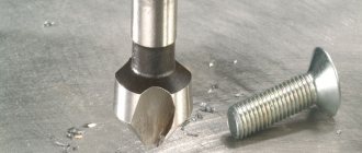
m is the process of processing with a special tool cylindrical or conical recesses and chamfers of drilled holes for the heads of bolts, screws and rivets.
Countersinks are:
1. cylindrical with a guide pin, a working part consisting of 4...8 teeth and a shank;
2. conical has a cone angle at the apex of 30, 60, 90 and 120 degrees;
4.9 Fanning
is a hole finishing process that produces high quality holes.
Machine reamers are made with uniform distribution of teeth around the circumference. The number of reamer teeth is even – 6, 8, 10, etc. The more teeth, the higher the quality of processing.
Manual and machine reamers are performed with straight (straight) and helical (spiral) grooves (teeth).
In Fig. 8 shows the machines of the drilling and boring group on which drilling and boring are carried out.
4.10 Metal riveting
is the connection of two or more parts using rivets, which are cylindrical rods with heads.
Metal riveting is used to create permanent connections between parts, as well as connections between sheet strip and shaped metal. Rivet connections are used for repairs of air ducts and fans, as well as for the manufacture of individual parts of ventilation systems.
Figure 8 – Machines for drilling and boring group:
a) vertical drilling, b) radial drilling, c) horizontal boring, d) coordinate boring
Metal riveting is divided into cold, hot and mixed. Rivets are made from mild steel and consist of a cylindrical shank and a head called a rivet.
The head, which is riveted at the other end of the rod and serves to fasten the parts, is called the closing head. A rivet is called ordinary if both rivet heads are above the surfaces of the riveted parts, and countersunk if the rivet heads are placed flush with the surfaces of the riveted parts.
The thickness of the rivets is selected by calculation. The length of the rivet shank between the heads should not exceed five shank diameters; If this ratio is absent, the rivet connection should be replaced with a bolted one. Riveting is done on special steel supports that have a recess in the shape of the rivet head so as not to crush it when riveting.
To prevent the support from bouncing off the head when striking with a hammer, its weight should be 4-5 times the weight of the hammer. The weight of the hammer is selected depending on the diameter of the rivet rod.
For riveting parts, in addition to a mechanic's hammer (preferably with a square head) and a steel support, a steel tensioner is used to seal and press the riveted parts to each other and to the rivet head and a steel crimp for the final formation of the closing head.
Tensioners and crimps are made from U8 tool steel. Their working end is hardened over a length of about 15 mm.
Metal riveting can also be done mechanized using pneumatic hammers and riveting machines.
Purpose and types of repairs.
Dismantling
operations of disassembling a machine or equipment into assembly units, components and parts are called. This involves disassembling detachable and, in some cases, permanent connections.
Repair
restoration of a machine is called the restoration of operability, accuracy, power, speed and other parameters of the machine that determine its service purpose. Repairs can be carried out as a result of breakdowns, failure or wear of individual parts, assemblies or the entire machine as a whole.
Assembly
machines are the operations of connecting parts into assembly units and assemblies in such a way that after assembly they form a machine that is suitable for use and meets its intended purpose.
To ensure the technical serviceability of machines and equipment, it is necessary to systematically monitor their technical condition and maintain it in accordance with the operating and repair instructions. In addition, the timing of preventive inspections and scheduled maintenance must be strictly observed.
The following types of repairs are distinguished: technical inspection, scheduled maintenance (routine), medium and major repairs.
The repair team is led by a foreman, and when repairing large objects, by a foreman or site manager. They are responsible for the organization and timing of repair work, the quality of repairs and safe working conditions for subordinate personnel.
The foreman, regardless of his administrative and technical responsibilities and leadership of the team, must be directly involved in the repair of the facility. He must thoroughly know the object being repaired, the complexity group of the repair, the technical requirements for parts and assemblies to be repaired or replaced, must carry out ongoing supervision and technical supervision of all work, and must make all necessary decisions on issues arising during the repair process.
6 Assembly of parts and assemblies.
There are assemblies based on complete interchangeability, partial interchangeability, selective selection of parts, fitting, and assembly with adjustment.
Immediately before starting assembly, you should once again carry out an external inspection of all parts included in the assembly kit or assembly. In this case, it is necessary to make sure that the parts correspond to the assembled assembly or assembly unit and can be installed in the appropriate places. Before assembly, they must be thoroughly washed and (if necessary) coated with a thin layer of lubricant. Before assembly, the parts that determine the appearance of the product must be primed and prepared for painting after assembly.
The sequence of assembly of parts and assemblies should be the reverse of the disassembly sequence. Assembly must be carried out in accordance with the developed technological maps. Proper preparation of parts for assembly speeds up the assembly process and improves its quality.
Riveted and bolted connections must ensure a reliable and tight connection of the assembled parts. To do this, you should use well and correctly manufactured parts (connected parts, rivets, bolts, nuts, washers, etc.), carefully carry out preparatory and basic operations, and use appropriate, serviceable tools to perform these operations.
Depending on the operating conditions of the part, assembly or assembly unit, nuts in threaded connections must be installed on split washers, cottered, locked, secured with a bending tendril of the washer or twisted wire.
Axles and shafts must be made in accordance with the drawings. Bearing journals must be made in accordance with the established tolerance and the permissible roughness value indicated on the drawing; There should be no radial or axial play.
Rolling bearings mounted on the shaft should not have any play or cracks in the cages. The alignment of the bearings must be maintained.
Sliding bearings must be made and adjusted by scraping in such a way that the entire inner surface of the bearing is adjacent to the surface of the journal, and the entire outer surface is adjacent to the surface of the seat in the housing. The holes and grooves for lubrication must be made strictly in accordance with the drawing so that the lubricant reliably and constantly flows into the bearings.
The condition for the normal operation of friction and gear drive mechanisms is the alignment of the shafts and bearings. When assembling the parts of the friction mechanisms, they must be adjacent to each other with the entire machined surface. The installation of cylindrical gears must be carried out in such a way that the correct engagement of the gear teeth is ensured. Correct engagement must be achieved by constant distance between the axes of the shafts on which the gears are mounted, strict parallelism of the axes and the location of the shafts and axes in the same plane.
The condition for the normal transmission of rotational motion from one shaft to another is the correct assembly of the shafts and coupling halves at the output ends of the shafts.
When assembling clutches, the shaft journals must be tightly seated in the bearing housings; there should be no beating. The shafts must be aligned and the coupling halves must be balanced.
7 Operations after assembly.
After assembling a machine or mechanism, it is necessary to inspect it in order to control the correctness of the assembly, eliminate any observed deficiencies, check the filling of power transmissions of various mechanisms with oil or lubricant, remove forgotten tools, unnecessary parts and auxiliary materials from the assembled machine or mechanism.
During the process of repairing an object, its external surfaces or individual parts may lose their presentation, and their corrosion resistance may decrease. To protect a repaired machine or mechanism from corrosion and give it a marketable appearance after repair and testing, they are painted, and parts that are not subject to painting are subjected to special treatment to give them corrosion resistance.
After inspecting and checking the readiness of the machine or mechanism for work, you should begin checking the object at idle speed, while observing labor protection and safety rules.
After checking the machine or mechanism at idle, a second inspection is carried out both of the entire machine and of its individual components and the most critical parts. Defects identified during inspection must be eliminated.
During operation of a machine or mechanism at idle speed for a certain time (different for different machines and mechanisms), some defects in the technical condition or performance of the repaired machine may not be detected. Therefore, after checking the idle operation, the machine is tested under load in operating mode. The load is increased gradually to the maximum possible under operating conditions.
The repaired machine (mechanism), which has demonstrated operational serviceability and compliance with technical requirements during load testing, is transferred to the customer. Upon transfer, a test and transfer report is drawn up, which indicates the technical data received, notes detected and unrepaired defects, as well as recommendations for operation.
The customer is also issued a warranty card (undertaking). For the consumer, a warranty card or commitment is a document confirming that the repaired object or its individual components and parts will not fail during the warranty period during normal operation and maintenance of the object during its operation. If during this period the repaired object, its part or assembly fails, or if the technical characteristics of the object (accuracy, speed, etc.) change during the warranty period, the workshop or enterprise that carried out the repair is obliged to eliminate the identified faults free of charge with its own forces.
Upon completion of the repair, the workplace must be put in order. All metal scrap and waste must be sorted and removed from the site. Cleaned and preserved tools, fixtures and equipment, remaining wood, detergents, oils and lubricants must be delivered to the appropriate warehouses.
If the repairs were carried out on the customer’s premises, the repaired area is handed over to the customer.
8
After disassembling the machine, assembly units and individual parts must be cleaned and washed from dirt, chips, foreign particles, carbon deposits, grease, and coolant in order to identify defects, improve the sanitary conditions of repair, as well as to prepare parts for restoration and painting operations.
Methods for cleaning parts:
1. Mechanical. Rust, old paint, hardened lubricant and carbon deposits are removed from parts using manual or mechanized brushes, rollers, scrapers, scrapers, and various machines.
2. Abrasive. Cleaning is carried out using sandblasting or hydrosandblasting of the part.
3. Thermal. Old paint and rust are removed by heating the surface of the part with the flame of a blowtorch or gas torch.
4. Chemical. Residues of lubricant, coolant, old paint are removed with special pastes and washing solutions, which include caustic soda, quicklime, chalk, fuel oil, etc.
Parts are washed with aqueous alkaline solutions and organic solvents. First in a hot solution, then in clean hot water. After this, the part is thoroughly dried with compressed air and napkins. Parts containing elements made of non-ferrous metals, plastics, rubber, and fabrics are not washed in alkaline solutions. Parts with polished and ground surfaces should be washed separately. Methods for washing parts:
1. Manual. Washing is carried out in two baths filled with an organic solvent (kerosene, gasoline, diesel fuel, chlorinated hydrocarbons). The first bath is for soaking and pre-rinsing, the second is for final rinsing. Washing is carried out using brushes, hooks, scrapers, cleaning material, etc.
2. In tanks using the immersion method. Washing is carried out in a stationary or mobile tank with a mesh on which the parts are placed, and a tube with an electric coil or coil for heating the washing solution to a temperature of 80-90 °C. As the latter, aqueous solutions of various combinations of soap, soda ash, trisodium phosphate, caustic soda, sodium nitrite are used with the addition of surfactants: sulfanols, the DS-PAC product and emulsifiers.
3. In washing machines. Stationary or mobile machines of various designs have one chamber (for washing only), two (for washing and rinsing) or three (for washing, rinsing and drying). Washing is carried out with washing solutions of the previously given composition heated to 70-90 °C, directed to the parts under pressure through special nozzles. Parts are fed individually or in baskets onto the conveyor. Washing equipment can be of auger, dead-end or through-type types, including those with an automatic processing cycle. After washing, the parts are washed with hot water and dried with a stream of hot (60-70 ° C) air, and the critical parts are wiped with napkins.
4. Ultrasonic. Washing is carried out in a special bath with heated washing liquid (alkaline solutions or organic solvents). A source of ultrasonic vibrations is placed in the bath, creating high-frequency elastic waves that accelerate the separation of contaminants from the surface of the part. The cleaning time for parts placed in a special mesh basket in the bath takes several minutes. Subsequent passivation of the parts is carried out by keeping them in an aqueous solution of 10-15% sodium nitrite at a temperature of 60-70 °C. Dry the parts by blowing with hot air or nitrogen.
9 The assembly process is developed according to drawings and assembly diagrams.
Assembly flow diagrams
represent a conventional image of the order in which the machine and its components are assembled during assembly. Assembly diagram - a document that organizes the assembly process of a machine or product, complements and explains the assembly drawing; In addition, using the assembly diagram, you can determine the order in which parts are supplied for assembly. These diagrams are clear and easy to use. If there are diagrams, the assembler clearly understands where he should start and how to finish the assembly.
Based on the diagram, the assembly technological process is developed and technological, route and operational assembly maps are drawn up.
Assembly flow sheets
are the main settlement documents. For each stage of assembly (assembly of components, assembly of units or mechanisms, general assembly of the entire machine), a set of technological maps is developed.
Assembly flow sheets for each stage outline all the factors that make up the technological process. Cards must contain: car name; annual production of cars; number of cars in the batch; name and description of the operation and transition for each assembly stage; indication of the workplace where the assembly is carried out; list of required devices, tools, transport devices; time to perform individual operations; total assembly time for all workers performing this operation; grade of work. In some cases, sketches illustrating assembly operations, devices, methods of securing a cable or chain for lifting and turning a product, etc. are placed in technological maps.
Route map
- a document that contains a description of the assembly process by operation. Route maps are used, as a rule, in small-scale and individual production.
Operation card
contains a more detailed description of operations, breaking them down by transition. In serial and mass production, assembly operational maps are developed separately for each assembly operation.
The development of the assembly technological process begins with drawing up a diagram of the assembly elements, and then developing a technological map, which is the main production document
Questions for self-control:
1 Who can be allowed to perform plumbing work?
2 What duties do you need to perform when working with a plumber's tool?
3 What is prohibited during metalworking?
4 What applies to plumbing tools?
5 What rules must be followed to maintain health?
6 List the rules for maintaining a workplace.
7 List the rules for performing plumbing work with power tools.
8 Give the names of technologies for processing metals without removing chips.
9 Give the names of metal processing technologies with chip removal.
10 Give the basic operations for washing and cleaning parts and assemblies.
11 List the main documents supporting plumbing and assembly work.
Bibliography:
1. Kostenko E.M., “Plumbing. A practical guide for a mechanic." - M.: NC Enas, 2006, 144.
2. Muravyov E.M., Plumbing. – M.: ed. "Education". 1990, 176
3. Pokrovsky B.S. General plumbing course: Textbook. allowance. – M.: JIC “Academy”, 2007 – 80 p.
4. Pokrovsky B.S. Basics of plumbing: A textbook for beginners. prof. education. – M.: JIC “Academy”, 2007. – 272 p.
Hole machining: methods and their applications
It is unlikely that the manufacture and assembly of any mechanism is possible without drilling and subsequent processing of holes in it, because drilling and plumbing have become simply inseparable concepts. In the same way, it is impossible to do without drilling in most other areas of activity. And after you make a hole in anything (no matter using drilling or others), you need to process it to adjust the dimensions and reduce the roughness of the walls.
Holes are processed using several methods, depending on the requirements for the workpiece. In particular, there are 3 main methods (drilling, countersinking and reaming), as well as varieties of these methods (drilling, countersinking, countersinking). Let's consider all these processes in more detail.
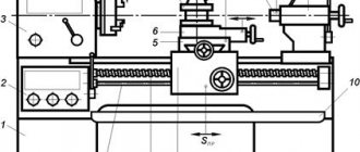
Radial drilling machines
The radial drilling machine belongs to the category of universal ones, which is why it has become very popular in production. Its main purpose is to process holes. Capable of performing the entire range of basic operations typical of radial drilling machines - drilling and reaming. It can also be used for countersinking. The basic operations also include the operations of reaming, trimming ends, cutting threads using taps, etc.
The range of operations performed by a radial drilling machine can be significantly increased by using fixtures and special tools. For example, the use of appropriate equipment on a 2n55 radial drilling machine makes it possible to turn internal grooves, cut round plates from sheets and many other operations that are normally performed on boring machines.
The radial drilling machine 2n55 uses preselective control of speeds and feeds, and easy hydraulic control of the spindle friction. It is possible to disconnect the spindle from the gearbox; there are reliable hydraulic clamps of the column and drilling head, which can work both together and separately. All controls of a radial drilling machine are located in a small area. All of the above can significantly reduce auxiliary time. If frequent tool changes are required when working on a radial drilling machine, machine manufacturers recommend using a quick-change chuck, and when cutting threads, a safety chuck for taps.
The 2C550 radial drilling machine (Fig. 3) is designed for processing holes in medium and large parts. The 2C550 drilling machine performs the following types of work: drilling, countersinking, reaming, facing and threading. The 2C550 radial drilling machine is effectively used in individual, small-scale and mass production.
Drilling
As you might guess, before machining a hole you need to do something to make it. So, the most common and common method of making holes is drilling.
Drilling is a type of machining for the purpose of forming holes, performed with a drill. This process can be “manual” (as you might guess, it is done with hand tools), as well as “machine” (performed on special machines).
Typically, to make a hole less than twelve millimeters in not particularly hard materials (such as structural steel, non-ferrous metals and alloys made from it, as well as polymer alloys), hand-held drilling devices are used.
And in order to make holes larger than 12 millimeters or to improve productivity in the case of mass production, the drilling process takes place on stationary or desktop drilling equipment (machines). The first ones are vertical or radial drilling.
Drilling technology
The process involves sequential removal of a layer of metal in a circle of a given diameter using a cutting tool. Drilling metal combines two types of motion - rotational and translational. To obtain the required hole dimensions in metal workpieces, it is necessary to accurately maintain the following technological process parameters:
- cutting tool rotation speed;
- speed of horizontal or vertical movement (depending on the relative position of the workpiece and drill).
A hole in the metal is obtained with the specified parameters only if the preparatory and main operations are correctly performed, as well as the selection of the necessary equipment and cutting tools. Pre-drilling is often performed to obtain the required accuracy. It's called draft. The operation is performed with a reduced accuracy class. Next, the finishing operation is carried out using high-precision machines and tools for metal workpieces.
In all cases, different types of drills are used to obtain the required hole. On drilling machines, a chuck with a fixed drill rotates and is brought to the surface of the workpiece. On metal-cutting machines, the drill is fixed in the tailstock of the machine, and the workpiece rotates. The second method allows you to obtain higher accuracy of the hole and the walls of the resulting hole.
Depending on the tasks, the following types of drills are used for both methods:
- spiral (the most common type of this tool);
- with soldered plates on the cutting edge;
- centering;
- cannon;
- feather (used for drilling holes in workpieces made of any type of wood).
Twist drills with their transverse edge exert pressure on the surface of the metal. This process accounts for more than 65% of the force during rotational and translational motion. At this moment, there is a significant increase in temperature of both the surface of the workpiece and the leading edge of the drill. Therefore, it is necessary to properly observe the thermal regime during the drilling process.
To speed up the cutting process in twist drills, so-called double sharpening is used. It allows you to work more efficiently on the hardest grades of metal, including cast iron. Such sharpening leads to an increase in chip width, the main angle decreases, and the durability and durability of the drill increases.
The technology for creating centering holes involves the use of special centering drills. They are made of tool steel and have a double-sided combined design.
Applying plates with increased strength to the cutting edge of the drill allows them to be used for drilling products made of cast iron, metal of increased hardness, dense building structures (concrete, stone, ceramic granite, etc.).
Feather drills differ in the design of the cutting edge. It is made in the form of plates. They are usually used to make holes in wood pieces. Sometimes special point drills are used to make holes in solid forgings and some types of castings.
Reaming
Hole drilling is a subtype of conventional drilling. At its core, it is an expansion of the size of the hole made earlier. Drilling holes is also done with drills.
Advice: It is highly not recommended to try to drill holes formed not by drilling, but by other methods, such as stamping. The reason is that such holes differ in the different hardness of the material of the internal walls.
During casting, scale is formed. During forging and stamping, non-uniform internal stress occurs in different places of a metal workpiece. This results in the drill being subjected to constantly changing loads during machining. And this can cause a displacement of the drill axis or even breakage.
If you process holes using a similar method (drilling and reaming), you can achieve X quality (accuracy measurement). The roughness after drilling at the hole walls is possible within the limits of no more than Rz 80.
Countersinking
The name “countersinking” was used to describe mechanical processing by cutting previously made holes. Its main purpose is to give the hole the desired shape and get rid of various defects, as well as increase accuracy (up to the VIII grade), reduce the roughness index (Ra 1.25 or less).
If the hole is not particularly large, then similar processing is done on a regular table-top machine, but if you need to process a larger hole, then it is easier to do it using special equipment on the foundation.
Separately, we note that there is no point in using manual equipment. It is simply impossible to achieve the desired indicators with it.
Countersinking has 2 subtypes, such as countersinking and countersinking.
When countersinking holes, you need to adhere to a number of rules:
- Drilling and countersinking are performed during one approach. Countersinking must be done after completion of drilling work, without removing the parts from the machine fixtures. In fact, during one “approach” the part is processed with two tools.
- When countersinking holes that have not been processed in housing parts, the part must be securely and firmly fixed.
- When choosing the size of the allowance, be sure to do this according to special tables.
- Countersinking must be done in the same operating mode of the machine as drilling in front of it.
- Labor safety rules must be observed similar to those used during drilling.
Countersinking
Countersinking is the finishing of cylindrical or cone-shaped holes that are intended to form recesses for recessed fastener heads. This is done with a special tool called a “countersink”.
There are a number of rules that must be followed when countersinking holes:
- A hole is countersunk only after it has been completely drilled.
- Drilling and countersinking holes are performed during one approach. Countersinking must be done after drilling is completed, without removing the parts from the machine fixtures. During one “approach”, processing is carried out with two tools.
- You can only use a low spindle speed (no more than 100 rpm), and at this time you need to use an emulsion. The processing depth can be checked with a regular caliper.
- If you use a cylindrical countersink for countersinking, in which the trunnion size exceeds the size of the hole that needs to be machined, you need to do the following. First, a hole is drilled that is the same size as the trunnion. Then it is countersinked, and after all this it is drilled to the desired size.
Deployment
Reaming is done by cutting. This type of processing guarantees increased accuracy (up to grade VI) and a minimum Ra of 0.63 or less.
During the process, a tool called a reamer removes microscopic chips from the walls of the hole. Deployment is done either manually or on machines (most often these are stationary machines).
Deployment also has its own rules:
1. It is necessary to strictly adhere to the allowance amount, according to special tables.
2. If deployment is done manually, it must be carried out in 2 stages: first rough, and then finishing.
3. When reaming a hole in a steel workpiece, the surface to be processed must be lubricated with an emulsion (mineral oil is also suitable). If the workpiece is made of cast iron, no lubrication is required.
4. If deployment is done manually, it must be done exclusively in a clockwise direction. Otherwise, the walls may be damaged by chips. By the way, the hole needs to be cleared of it from time to time.
5. Drilling and reaming holes must be done in one “approach”, without removing the part from the fasteners and processing the part with two tools in turn.
Safety, general tips
When working with power tools, it is important to remember human safety and prevent premature wear of the tool and possible defects. In this regard, we have collected some useful tips:
- Before work, you need to check the fastenings of all elements.
- When working on a machine or with an electric drill, clothing should not contain elements that could be affected by rotating parts. Protect your eyes from chips with glasses.
- When approaching the metal surface, the drill must already be rotating, otherwise it will quickly become dull.
- You need to remove the drill from the hole without turning off the drill, reducing the speed if possible.
- If the drill does not penetrate deep into the metal, it means that its hardness is lower than that of the workpiece. Increased hardness of steel can be detected by running a file over the sample - the absence of traces indicates increased hardness. In this case, the drill must be selected from carbide with additives and operated at low speeds with low feed.
- If a small-diameter drill does not fit well in the chuck, wrap a few turns of brass wire around its shank, increasing the grip diameter.
- If the surface of the workpiece is polished, put a felt washer on the drill to ensure that it does not cause scratches even when it comes into contact with the drill chuck. When fastening workpieces made of polished or chrome-plated steel, use fabric or leather spacers.
- When making deep holes, a rectangular piece of foam placed on a drill can serve as a meter and at the same time, while rotating, blow away small chips.
rmnt.ru