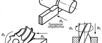
Cutting modes in machining are a set of operating parameters that determine the speed, force and depth to which the cutter is immersed into the part during the process of removing a layer of metal from its surface.
Their basic values are determined by calculation based on the geometry of the cutting edge of the tool and the workpiece, as well as the speed of their approach. Real metal processing processes are influenced by many factors related to the characteristics of the tool used, machine equipment and the material being processed.
Therefore, empirical formulas are used to calculate technological cutting conditions. And the basic values are included in their composition along with such reference values as groups of correction factors, durability values, parameters of processing conditions, etc.
Cutting modes affect not only the specified accuracy and processing class of the product. They determine the force with which the tool edge acts on the metal, which directly affects power consumption, the level of heat generation and the wear rate of the tool.
Therefore, the calculation of their parameters is one of the main tasks of technological services of enterprises. Despite the many varieties of metal-cutting equipment and tools, all machining is based on common principles.
Therefore, methods for calculating cutting modes are unified and systematized into three main groups: for turning, for drilling and for milling. All other types of calculations are derivative.
The second most common type of machining after turning is drilling. It is also equivalent to reaming, countersinking, and drilling. When calculating cutting conditions, one can, neglecting the rigidity of the processing system, imagine that this is simultaneous boring with several cutters, so the calculation principle will be similar to turning. However, for small drill diameters, less than 10 mm, cutting modes are calculated based on the integrity of the drill after processing. In other words, the modes are calculated in such a way that the drill does not break, so the calculation is made based on the strength characteristics of the tool.
However, during experiments with the technique, an error was identified due to which the cutting speed was too high, this was expressed by the duration of drilling, but high tool life, and high quality of processing. Whether this is a plus or a minus must be decided for a certain task, since low feeds can cause the cutting part to quickly become dull (or even stick), but at too high feeds, the tool is likely to break, not to mention reducing the safety of processing.
Our methodology for calculating drilling modes can be found below. In the corresponding forum topic you can download a macro for automatically calculating cutting conditions for drilling work.
Methodology for calculating cutting conditions during drilling operations
When drilling, it is recommended to set modes based on the power of the equipment used. The most convenient cutting tool material is high-speed steel (P18, P6M5). Feed rates during drilling operations are calculated using the formula:
S-feed, mm/rev
D - drill diameter, mm
C-coefficient, depending on the material being processed and other technological factors (surface cleanliness, presence of further processing, etc.) (Table 1)
Kls is the feed coefficient, depending on the chip exit condition (Table 2)
| Processed material | NV | Feed group determined by technological factors | ||
| I | II | III | ||
| Steel | ≤160 | 0,085 | 0,063 | 0,042 |
| 160-240 | 0,063 | 0,047 | 0,031 | |
| 240-300 | 0,046 | 0,038 | 0,023 | |
| >300 | 0,038 | 0,028 | 0,019 | |
| Cast iron | ≤170 | 0,130 | 0,097 | 0,065 |
| >170 | 0,078 | 0,058 | 0,039 | |
| Non-ferrous metals | Soft | 0,170 | 0,130 | 0,085 |
| Solid | 0,130 | 0,097 | 0,065 | |
Table 1
Feed group I - drilling blind holes or drilling without tolerance according to the 5th accuracy class or for subsequent drilling
Group II feed-drilling of blind and through holes in parts of non-rigid structure, drilling for threads and reaming for subsequent processing with a countersink or reamers
Group III feed - drilling of blind and through holes and drilling for further processing
| Hole length in diameters up to | 3 | 4 | 5 | 6 | 8 | 10 |
| Kls coefficient | 1.00 | 0.95 | 0.90 | 0.85 | 0.80 | 0.70 |
table 2
Cutting modes when drilling
The power consumed when drilling depends on the torque. Torque is calculated using the formula:
Mkr - torque perceived by the drill when cutting, N*m
Cm, q, y - coefficients for torque during drilling, depending on cutting conditions (Table 3)
D - drill diameter, mm
S-feed, mm/rev
Kmr is the coefficient for torque, depending on the mechanical properties of the material (Table 4)
| Processed material | Cm | q | y |
| Structural carbon steel, | 0,0345 | 2,0 | 0,8 |
| Gray cast iron 190 HB | 0,021 | 2,0 | 0,8 |
| Copper alloys | 0,012 | 2,0 | 0,8 |
| Aluminum alloys | 0,005 | 2,0 | 0,8 |
Table 3
| Processed material | KMR | Indicator n | ||
| Steel | C ≤0.6% | -1,0 | ||
| 1,75 | ||||
| 1,75 | ||||
| chrome steel | 1,75 | |||
| С>0.6% | 1,75 | |||
| Gray cast iron | 1,7 | |||
| Copper alloys | 1 | — | ||
| Aluminum alloys | 1 | — | ||
Table 4
For normal drills with a diameter above 10 mm there is no danger of breaking from excessively high torque, since for these diameters the highest stresses occurring in the drill are usually limited by the rate of dullness as cutting speed and feed increase. For drills with a diameter less than 10 mm, it is recommended to calculate the torque according to
to ensure instrument integrity.
By equating and it is possible to calculate the maximum possible feeds for small-diameter drills when drilling a given material (Table 5).
| Processed material | Steel | Cast iron | Copper alloys | Aluminum alloys |
| Maximum possible feed, mm/rev | 0,01 | 0,019 | 0,037 | 0,11 |
Table 5
To ensure AIDS rigidity when drilling, it is necessary to install the drill in the chuck with the minimum possible overhang (3-5 mm more than the depth of the hole being machined).
The cutting speed when drilling is calculated by the formula:
The rotation speed is calculated using the formula:
Table of calculations of modes when drilling on the 2A135 machine in Appendix 1.
Countersinking and reaming
The feed rate for countersinking and drilling is calculated similarly using the formula:
Torque is calculated using the formula:
Select coefficient values Сm, x, y, q according to Table 6
| Processed material | Cm | q | x | y |
| Structural carbon steel, | 0,09 | 1,0 | 0,8 | 0,8 |
| Gray cast iron 190 HB | 0,085 | 1,0 | 0,8 | 0,8 |
| Copper alloys | 0,031 | 0,85 | 0,8 | 0,8 |
| Aluminum alloys | 0,02 | 0,85 | 0,8 | 0,8 |
Table 6
D - drill diameter
d - diameter of the previously drilled hole
The cutting speed is calculated by the formula:
The rotation speed is calculated using the formula:
Deployment
To determine the reaming torque, each tooth of the tool can be considered as a boring cutter.
sZ - feed per tool tooth (equal to s/Z)
s-feed, mm/rev
Z- number of reamer teeth
Coefficients Сp, x, y in table 7
| Processed material | Cp | x | y |
| Steel | 300 | 1 | 0,75 |
| Gray cast iron 190 HB | 92 | 1 | 0,75 |
| Aluminum alloys | 40 | 1 | 0,75 |
| Copper alloys | 55 | 1 | 0,66 |
Table 7
The cutting speed is calculated by the formula:
The rotation speed is calculated using the formula:
Table of calculations of modes when deploying on a 2A135 machine in Appendix 2.
When introducing the calculation methodology in the TechnoPro system, it is recommended for drilling and reaming to enter the calculated modes into the information database, thereby avoiding programming the calculation conditions and simplifying the operation of the system. To calculate the modes for countersinking and drilling, it is necessary to program the conditions using the coefficients from Table 6.