Metal spraying is a technology for changing the surface structure of a product in order to acquire certain qualities that increase performance characteristics. Processing is performed by applying a homogeneous metal layer to a part or mechanism. Special powder compositions are used as consumables, which are subjected to heat treatment and give them significant acceleration. Upon impact contact with the surface, particles are deposited on the plane.
The technology appeared at the beginning of the 20th century as an alternative to traditional methods of surface modification of metals. As methods of spraying metal products were studied and developed, a separate industry was formed - powder metallurgy. This is a technology for producing powders for making various products from them.
In modern industry, metal spraying is considered one of the most economical processing methods. Compared to bulk alloying, the technology makes it possible to obtain the necessary performance properties of the surface at lower costs.
The essence and purpose of metal spraying
The application of protective coatings to metal is necessary for many industries. The purpose of spraying products is to increase the basic service life of the workpiece. The protective layer provides reliable protection against the following harmful factors:
- exposure to aggressive environments;
- vibration and alternating loads;
- thermal effects.
The composition of the multicomponent powder is selected based on the required performance qualities.
The use of several components increases the risk of obtaining a non-uniform coating due to delamination of the protective layer. To solve this problem, special rope-type materials are used, where the powder is fixed with a plastic binder.
During the spraying process, a stream of particles is directed onto the metal surface. When interacting with the surface, the sprayed elements are deformed, which ensures reliable contact with the product. The quality of adhesion to the workpiece depends on the nature of the interaction of particles with the substrate, as well as the crystallization procedure of the protective layer.
Ultrasonic pressure treatment and ultrasonic hardening
The main technological parameters of ultrasonic hardening (USH) are the duration of exposure (t), ball diameter (dsh) or rounding radius of the working part of the tool (r), vibration amplitude (Ak), effective mass of the tool (Gin), longitudinal feed (s), number passes (i), the speed of movement of the part being hardened (v), the initial surface roughness (Ra) and the quality of the surface layer.
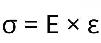
To improve the physical and mechanical properties of parts, finishing and strengthening treatment by surface plastic deformation (with a spherical or cylindrical tip) is used. In this case, the metal of the asperity protrusions moves in both directions from the point of contact with the deforming element. The height of the irregularities decreases, forming a new microrelief. To obtain the required surface roughness, it is necessary to apply the minimum necessary force to the deforming element, sufficient for plastic deformation to occur.
When rolling and rolling with roller and ball heads, mandrating, and pulling with smoothing broaches, the shape of non-rigid parts and parts of variable rigidity may be distorted. The application of ultrasonic vibrations (UV) to the deforming tool reduces the magnitude of the static load during plastic deformation of metals.
The installation diagram of the ultrasonic device (Fig. 1) includes an ultrasonic generator, a magnetostrictive transducer 5, a waveguide 3 and a deforming tip 2. The acoustic system is mounted in a movable housing 4, which can move along the axis of the fixed housing. The installation and regulation of the required radial force is carried out using a calibrated spring 7 and a screw 8. The tip 2 performs ultrasonic testing and with a small force P is pressed against the workpiece 1.
Rice. 1. Scheme of ultrasonic hardening with a spring-loaded ball or diamond tip
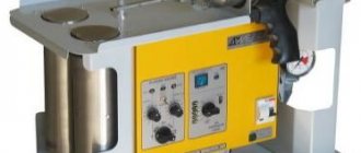
In practice, steel or carbide balls can be used as a tool, loosely or rigidly connected to the waveguide of the transducer, and in diamond burnishing, polished diamond crystals are used, sealed in steel holders. The radius of curvature of the working part of the diamond tip is 1. . . 4 mm and depends on the processing conditions, the material of the processed surface and the rigidity of the technological system. It has been established that under the influence of ultrasonic sound with an amplitude Ak = 10 μm, the rate of deformation of the surface layers increases 100 times and is accompanied by hardening. Serial equipment is used as equipment for performing ultrasonic hardening. The ultrasonic emitter is fixed in the tool holder (Fig. 2).
Spraying methods, equipment used
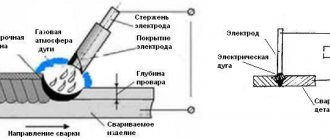
At the dawn of the development of technology, the processing of products was carried out using a burner nozzle and a conventional compressor, which provided heating of the consumable material and high-speed transfer to the deposited surface.
As technology developed, new methods for obtaining protective coatings were developed. The next stage of development was the use of electric arc equipment. The design of such a wire-type metallizer was developed in 1918. There are two types of spraying process:
- Gas-dynamic. Processing is carried out with the smallest particles, the size of which does not exceed 150 microns.
- Vacuum. The procedure takes place under conditions of reduced pressure. The formation of a protective layer occurs during the process of condensation of the sprayed material on the base surface.
Let's consider the main processing methods, as well as the features of the spraying equipment used.
Sputtering in magnetron installations
Magnetron vacuum metallization technology is based on the action of a diode gas discharge in crossed fields. During operation of the installation, gas ions are formed in the plasma of the glow charge, which affect the sprayed substance. The main elements of the magnetron system are:
- anode;
- cathode;
- magnetic node.
The function of the last element is to localize the plasma at the base of the sputtered substance - the cathode.
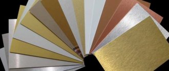
Any magnetic system consists of central and peripheral permanent magnets. The cathode is supplied with a constant voltage from a power source. Under the influence of current, the target is sputtered, provided that the charge remains consistently high throughout the entire procedure. Advantages of the magnetron method:
- high performance;
- accuracy of the chemical composition of the deposited substance;
- uniformity of coverage;
- no thermal effect on the workpiece being processed;
- possibility of using any metals and semiconductor materials.
Using installations, thin protective films are produced in a special gas environment. The sprayed material can be metals, semiconductors or dielectrics. The rate of layer formation depends on the current strength and working gas pressure.
Ion plasma sputtering
One of the types of vacuum deposition of metal onto a surface.
The method is the next stage in the development of thermal deposition technology, which is based on heating the starting materials to the boiling point with their further condensation on the workpieces. The schematic diagram of equipment for ion plasma planting includes the following elements:
- anode;
- target cathode;
- hot cathode;
- camera;
- workpiece
Installation algorithm:
- A reduced pressure is created in the chamber.
- Current is supplied to the thermionic cathode, which is an auxiliary source of electrons.
- As a result of heating, thermionic emission occurs.
- Inert gas is supplied to the chamber. Argon is the most popular.
- A voltage arises between the anode and thermionic cathode, which initiates the formation of a plasma glow charge.
- A powerful charge is applied to the cathode.
- Positive ions affect the sputtered target material.
- Sputtered atoms are deposited on the workpiece in the form of a thin coating.
Ion plasma deposition is used as decorative or protective coatings, which are characterized by high density and strength, as well as the absence of changes in the stereochemical composition.
To change the color of the product, reactive gases are added to the technological cycle: oxygen, acetylene, nitrogen or carbon dioxide.
Plasma spraying
One of the most effective is the diffusion metallization method. Features of the technological process:
- The operating temperature of the plasma can reach 6000 ºC. This contributes to a high rate of deposition of the composition on the surface. The duration of the process is tenths of a second.
- It is possible to change the structural composition of the workpiece surface. Together with the hot plasma, individual chemical elements can diffuse into the upper layers of the product.
- The plasma jet is characterized by constant pressure and temperature. This has a positive effect on the quality of spraying.
- Due to the short processing time, the workpiece is not exposed to harmful surface factors such as overheating or oxidation.
A spark, pulse or arc discharge is used as an energy source for plasma formation.
Laser deposition
Laser metal deposition is used to achieve the following goals:
- increasing the strength of the surface layer;
- restoration of product geometry;
- reducing the friction coefficient;
- protection against corrosion processes.
Unlike other metallization methods, the heat source is laser radiation energy. High focusing accuracy allows energy concentration to be concentrated exactly in the work area. This reduces the thermal effect on the workpiece, which avoids changes in the geometry of the product and makes it possible to spray virtually any material.
Due to the high cooling rate, structures with high hardness are formed in the surface layer of the metal, which increases the performance characteristics of the part.
Vacuum spraying
Vacuum metal deposition is an effective and universal method of surface metallization. Using this method you can process almost any product. During the technological cycle, a number of transformations occur with the material:
- evaporation;
- condensation;
- adsorption;
- crystallization.
The performance of the process depends on many factors: the structure of the workpiece, the type of material being applied, the flow rate of charged particles and many others.
Vacuum units differ in their operating principle. There are continuous, semi-continuous and batch equipment.
Advantages of axial powder input
Axial powder injection is a quantum leap in plasma spraying technology. The point here is not only that with axial input, powder losses are significantly reduced, but also that the possibility of spraying completely different powder materials that are unsuitable for radial input opens up. Since this aspect is fundamentally important for understanding the following sections, we will dwell on it in more detail.
So, what happens when powder is radially introduced into the flame jet at the nozzle exit? We list the disadvantages of such input:
- Only very narrow fraction powders are suitable for radial injection, for which it is necessary to precisely select the pressure of the carrier gas. What does this mean?: If the carrier gas pressure is insufficient, the powder particles will “bounce” off the flame jet; if the carrier gas pressure is too high, they will “shoot through” this flame; if the powder consists of particles of different sizes, then it is in principle impossible to select the “correct” pressure of the carrier gas: the smallest particles will always “bounce off”, and the largest ones will always “shoot through”, that is, neither of these particles will be in the sprayed coating there won’t be, but only some “average” particles. Fine-grained powders are especially difficult to introduce due to their increased dispersion by the carrier gas (a typical dust cloud around a torch).
- When introducing radial powder, it is impossible to use in the powder mixture not only particles of different sizes, but also different densities (different masses) for the same reason: heavier particles fly through the flame more easily than lighter ones. Thus, attempting to use complex powder mixtures will result in a distortion of the coating composition compared to the composition of the powder mixture.
- An increase in the velocity of plasma-forming gases complicates the radial injection of powder, since the ranges of required carrier gas pressures and particle size distributions are further narrowed. In practice, this means the following: the higher the flame speed, the lower the spraying efficiency during radial powder injection. It is impossible under any circumstances to introduce all the powder into the flame without loss.
- The location of the powder nozzles next to the hot flame zone causes their heating, which is compensated only by cooling by the gas carrying the powder. If the speed of the cooling gas is not enough for cooling, then powder particles can stick to the edges of the nozzle opening, forming sagging. The stuck pieces periodically come off the nozzle, fall into the flame and cause a characteristic defect - “spitting”, leading to the formation of coarse porous inclusions in the coating. Since the flow rate of the carrier gas is strictly related to the flame parameters (see point 1), a problem arises: for some powders there are simply no parameters that eliminate the “spitting” effect, especially if these powders are low-melting and/or fine-grained.
Switching to axial injection of powder allows you to completely get rid of the above problems:
- Carrier gas pressure and velocity are no longer tied to flame and powder parameters. The only condition is that the pressure of the carrier gas must be slightly higher than the pressure of the plasma-forming gas in the nozzle at the point where the powder is introduced. Due to the axial input, any powder is completely captured by the flame.
- It is always possible to select a pressure of the carrier gas at which “spitting” associated with powder sticking to the edge of the hole in the powder nozzle will not occur.
- It is possible to use powder mixtures of any complexity and fractional composition. Particles of different sizes will acquire different speeds and temperatures, but all will eventually take part in the formation of the coating. The fact that small particles become significantly hotter than large ones when axially introduced into a plasma flame opens up new possibilities for the design of powder mixtures. The main part of this book is devoted to the creation of such polyfractional compositions.
The author was very fortunate to have had an Axial III plasmatron with axial powder injection at his disposal for many years. If not for this, the creation of new multicomponent coatings would simply be impossible.
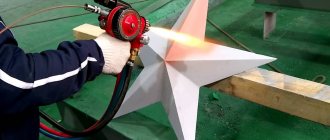
Powder coating
Powder coating of metals with polymer materials is the most effective way to obtain high-quality coatings with decorative or protective properties.
Spray powder is a mixture of rubber and colored pigment. It is applied to the surface using a special electrostatic gun. In this case, the powder acquires a charge, which facilitates effective coupling with the workpiece.
To obtain a high-quality coating, it is necessary to carefully prepare the surface. The essence of the procedure is to clean the workpiece from dirt and traces of corrosion, followed by degreasing.
To use the technology on an industrial scale, special automatic or manual painting lines are used.
Metal spraying is one of the most effective surface modification technologies. Processing allows you to obtain a coating with decorative or protective qualities that increase the performance properties of the product. What do you think about this technology? Which method do you think is the most promising? Write your opinion in the comments block.
Rolling and rolling out surfaces
Similar to ultrasonic hardening treatment, the same equipment is used to perform finishing and hardening treatment of the external surfaces of parts by rolling, and the internal surfaces by rolling.
Rice. 2. Ultrasonic hardening of the shaft surface on a 16K20 screw-cutting lathe
Depending on the material of the part, the pressure on the roller is 5. . . 20 MN/m2 with a number of passes up to 4. Rolling provides a roughness of the treated surface Ra = 0.4. . . 0.05 µm. The rolling tool shown in Fig. 3, installed in the tool holder with shank 7.
Rice. 3. Hardening treatment of the outer surfaces of parts by rolling
Rolling of the surface to be treated is carried out by ball 2, which rests against the outer race of bearing 10, mounted on axis 9, and is kept from falling out by cap 8. Under the influence of rolling force, ball 2 is pressed out and moves quill 3 in the bore of housing 4, which compresses spring 5. With the help of Screw 6 adjusts the compression force of the spring. For rolling processing, the tool holder of a lathe with a rolling tool is brought until the ball comes into contact with the surface of the pre-processed part. Then, using the caliper transverse feed screw along the dial, a preload of 0.5 is created. . . 0.8 mm. Set the spindle speed to 1200...1500 min-1 and longitudinal feed 5 = 0.3. . .1.5 mm/rev. , turn on the machine and make 2-3 longitudinal passes to the right and left°. Spindle oil is used as a cutting fluid.
Balls and rollers for rolling (rolling) are made of hardened steel or hard alloy
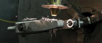
Surfacing of surface layers
Surfacing of surface layers is the process of applying a coating to a workpiece using electric welding (in a protective gas environment, electroslag, under a layer of flux) or a plasmatron. Using surfacing, you can restore the dimensions of a worn part or apply a hardening coating to the workpiece. To obtain the coating, materials of different physical states are used: metal powder, cored wire, metal wire, pieces of chopped wire (grits), flexible cord materials.
Rice. 6. Metallization of steel structures in the field
Surfacing installations consist of two parts - electromechanical and energy. Electromechanical equipment ensures the application of a new strengthening layer of metal to the desired part of the workpiece, and energy equipment ensures the melting of the additive and its connection to the workpiece. Based on this, the composition of the equipment is determined. The general diagram of the energy part of the equipment for surfacing with a plasmatron is similar to that shown in Fig. 4. In many cases, metal-cutting machines are used as an electromechanical part. When surfacing on cylindrical surfaces, it can be a lathe; when hardening flat surfaces, it can be a milling machine, etc. When surfacing large flat surfaces, it is most advisable to use multi-electrode machines or strip electrodes.
When surfacing complex surfaces, manipulations with the gun, torch and holder are carried out manually, sometimes in semi-automatic mode and less often in automatic mode in the presence of additional devices or special manipulators. A general view of the installation for mechanized plasma powder surfacing of cylindrical parts is shown in Fig. 7, a, in Fig. 7, b - manual surfacing of a strengthening coating on the punch.
A mixture of flammable gas (propane, propane-butane, propylene, natural gas) is burned in the catalytic combustion chamber of the gun, generating a high-speed jet of combustion products. Coating material in the form of an alloy or composite powder is supplied here. It is heated in the combustion chamber and accelerated in the jet, forming a coating when the impact of particles on the substrate. The AC-HVAF gun, for example, accelerates powder particles up to speeds of 700. .800 m/s and produces a jet with a diameter of more than 16 mm and a length of over 250 mm, which is much longer than the spraying distance, which is usually 125. . .180 mm. The diameter of the flow of sprayed particles in the jet is usually 3. . .5 mm. The thickness of the surface-hardened metal layer, formed by one or several layers, can be different: usually 0.5. . .10 mm, but a thicker layer can be applied, and the mass of deposited metal is 3.5. . . 4.5 t, as when restoring rolling rolls.
Rice. 7. Installation diagram for surfacing with metal powder and performing manual surfacing : 1 - gearbox; 2 - clamping chuck; 3 - powder feeder; 4 - workpiece; 5 — spray burner (gun); 6 — supporting rollers; 7 — air preparation device; 8 — air receiver; 9 — cylinders with working gases; 10 - compressor; 11 — pipeline for supplying powder to the burner.
To restore parts with high wear, electric arc surfacing is used with a consumable electrode under a layer of flux using additional filler material. The layout of the installation is similar to that shown in Fig. 6 7, but the energy part includes electric welding equipment instead of gas supply equipment