Design features
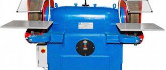
The TSh 3 machine, at first glance, is similar to its predecessor models - the TSh 1 and TSh 2 machines. The machine has a classic layout - an electric motor is installed on the bed, which drives the working shaft.
Each of the grinding heads, which are mounted on the shaft, has protective devices with a through hole for installing the elements being processed. Fixation of workpieces is carried out using special platforms, which are located near each working unit.
Other design features of the machine include:
- To protect the operator from production waste, transparent shields are installed above the working areas.
- The design of the device includes a lamp to illuminate the work area.
- Dimensions allow the device to be installed in small spaces.
- A special relay blocks engine operation if the permissible load is exceeded.
- Extreme rigidity of the frame is ensured by special metal sheets with stiffeners.
- The bed is designed in such a way that the operator has the ability to control the parameters of the working area.
- The height of the machine allows you to work on it even without a workbench, but before installing the machine on the floor, you should check its levelness and accuracy.
Key changes in the design of the machine, compared to previous models in this line, were made to increase operator safety and simplify his work with the machine. The materials from which the key components of the unit are made significantly increase the durability of its operation.
Regulations for specialist actions
Work with the machine must be carried out taking into account certain recommendations:
- There is play between the workpiece and the grinding wheel. It is necessary to ensure that its thickness is half that of the workpiece.
- Work with workpieces should only be done after the main shaft has completely untwisted. Otherwise, damage to the machine or injury to the operator may occur.
- The unit is installed on a special workbench or on the floor. In this case, the weight of the unit is taken into account.
- After installing the equipment, it is necessary to check its stability. If the machine wobbles, this will lead to poor-quality processing of workpieces.
- If the equipment is damaged or inoperative, its operation is strictly prohibited for safety reasons.
- The parts to be turned must be installed above the horizontal line, the passage of which is observed in the center of the grinding wheel. For this purpose, handholds are installed.
- The presence of flammable and explosive substances in the room where they are working on the part is strictly prohibited.
- The equipment operates from a three-phase network, the voltage of which is 380 volts.
- The frame and other components of the device must be regularly maintained. They must be cleaned of waste that appears during the processing of metal products.
- It is allowed to work with the unit only in special clothing; in addition, the operator is recommended to wear safety glasses.
Special clothing for working on the unit
Precautions when working with equipment
- Conscious adherence to safety measures during operation, as well as during transportation and installation indoors.
- In the electrical circuit, ensure the serviceability of the emergency de-energization device.
- The workroom should be equipped for fire protection.
- Place emergency medical supplies and medications within easy reach.
- Work clothes should be adjusted so as to prevent accidental contact with rotating mechanisms.
The prototype of the new screw-cutting lathe MetalMaster -1830 remains the TSh-3 model of the machine even before the perestroika, Soviet brand Universal - 3. It looks aesthetically pleasing, is equipped with a smooth drive control, and is equipped with electronics. And, most importantly, the machine has made a qualitative transition from an amateur machine to the category of a professionally advanced machine for metalworking.
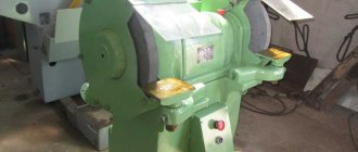
TSh-3 sharpening and grinding machine (Russia)
| PARAMETER NAME | MODEL TSH-3 |
| Diameter of worn circle, mm: | 240 |
| Outer diameter of the circle, mm: | 400 |
| Circle height, mm: | 40 |
| Bore diameter, mm: | 127 |
| Unbalance class: | class 2 or class. 1 |
| Voltage, V: | 380 |
| Height of circle centers from the base, mm: | 974 |
| Maximum cutting speed, m/s: | 20 |
| Adjustable hand rests pcs.: | 2 |
| Shaft rotation speed, rpm: | 1000 |
| Net weight, kg: | 170 |
| Gross weight, kg: | 217 |
| Power, kWt: | 3 |
| Overall dimensions, mm: | 690x492x1270 |
| Overall dimensions in packaging, mm: | 1400x840x1000 |
The TSh-3 sharpening and grinding machine is very popular among equipment suppliers and is widely used for production purposes, in workshops and production laboratories, and is often purchased by private individuals specializing in individual turning and metalworking work. Regardless of production requirements, machines are used to carry out high-quality turning and metalworking work, sharpening production tools, grinding and polishing products. The main drive has a power of 3 kW at a rated speed of 1000 rpm.
The TSh-3 series sharpening and grinding machine has proven itself well in the final processing of parts; it allows you to remove chamfers, burrs and polish metal parts with the highest quality. The device is also used for high-quality sharpening of various production tools and is indispensable in the work of large enterprises that have the necessary repair facilities at their base.
The TSh-3.20 modification machine is equipped with a protective screen, engine blocking when lifting, and a stand.
Complete set of sharpening machine TSH-3
The machine is delivered assembled, in special packaging (allows for its transportation and long-term storage).
The set and price of the machine includes:
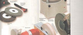
- Grinding wheels 2 pcs: 400x40x127, 25A F46 K-L1700 (GOST P52588-2006), 400x40x127, 64C F46 K-L1700 (GOST P52588-2006);
- Work area protection: circle fencing 2 pcs., protective screens 2 pcs.;
- Work area lighting: local lighting lamp 1 pc.;
- Electrical control: push-button, with zero protection.
- Technical documentation (passport, instruction manual, etc.) and additional components in accordance with the supply agreement.
TSh-3 machines are not equipped with a device for shutting off the electric motor when the protective screen is raised.
Model range of machine TSH-3
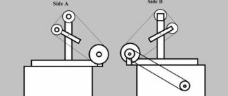
Direct drive machines
and a grinding wheel
400x40x127 mm.
3 kW, 1000 rpm. TSh-3 (analogous to TShS 400)
TSh-3.20 (analogous to TShS 400.1) with additional engine blocking
TSh-3.25 with vacuum cleaner
TSh-3.35 with vacuum cleaner and engine blocking
Direct drive machines
and a grinding wheel
400x40x127 mm. 5.5 kW, 1500 rpm.
TSh-3M (analogous to 3K634, 3B634, 3T634-01)
TSh-3M.20 with additional engine blocking
TSh-3M.25 with vacuum cleaner
TSh-3M.35 with vacuum cleaner and engine blocking
Belt driven machines
and a grinding wheel
400x40x127 mm .
3 kW, 1000 rpm. TSh-3M
TSh-3M.20 with additional engine blocking
TSh-3M.25 with vacuum cleaner
TSh-3M.35 with vacuum cleaner and engine blocking
Read the SELECTION GUIDE FOR GRINDING AND GRINDING MACHINES TSh SERIES
Precautions when working with equipment
- Conscious adherence to safety measures during operation, as well as during transportation and installation indoors.
- In the electrical circuit, ensure the serviceability of the emergency de-energization device.
- The workroom should be equipped for fire protection.
- Place emergency medical supplies and medications within easy reach.
- Work clothes should be adjusted so as to prevent accidental contact with rotating mechanisms.
The prototype of the new screw-cutting lathe MetalMaster -1830 remains the TSh-3 model of the machine even before the perestroika, Soviet brand Universal - 3. It looks aesthetically pleasing, is equipped with a smooth drive control, and is equipped with electronics. And, most importantly, the machine has made a qualitative transition from an amateur machine to the category of a professionally advanced machine for metalworking.
Structural features
The unit consists of several key components:
- beds;
- headstock;
- drive;
- electrical equipment;
- calipers;
- tailstock.
All electrical equipment of the machine is characterized by the presence of insulation. Additionally, the unit has a grounding wire; this feature guarantees a high level of operator safety while working on the equipment.
The electrical equipment is contained in a box that is tightly closed with a lid equipped with two screws. One of the screws performs the grounding function.
The bed is characterized by the appearance of a guide made of a cylindrical type. This is the basis of the main mechanisms of the unit; on the left side of the headstock there is a bracket. An electric motor is attached to it.
The machine is equipped with special handles and handles. With their help, the feed movement is regulated, the caliper is activated and the direction of its movement is selected, and the tool holder is launched.
Tool holder
The station wagon is equipped with a special handle, with its help the main movement is regulated, and the direct or reverse movement of the spindle is activated and its operation is stopped.
Thanks to the universal technical equipment of the unit, it is easy to operate; manipulation allows even a master without relevant experience to perform this action.
Recommendations from experts
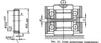
Incorrect or prolonged operation of equipment often leads to breakdown of components and parts. If the operator hears a knocking noise from the bearings, then they need to be replaced. If the equipment is operated with faulty bearings, the failure can lead to damage to other components and assemblies.
Strong noise or rapid heating of the motor requires an inspection of its windings. In some cases, the unit is completely replaced. If the motor suddenly stops, this indicates a malfunction in the electrical network.
This situation indicates a breakdown of the trigger mechanism. If the engine is unable to gain speed, experts conclude that it is faulty.
The most common cause of breakdown is interruptions in the supply of electrical energy. If this problem occurs frequently, it is recommended to purchase a special stabilizer.
Types of stabilizers
Independent disassembly of the structure is strictly prohibited, especially without the presence of certain experience, skills and knowledge.
In such a case, it is recommended to seek help from a specialist; he will not only fix the breakdown, but also ensure safe operation of the equipment in the future.
To avoid injury and equipment damage, the operator must strictly follow the operating instructions. Cleaning of the main components of the unit must be carried out constantly.
The benchtop turning unit allows for the most precise processing of metal workpieces. To achieve this goal, you must adhere to the rules of its operation. Due to the simplicity of the unit design, precision processing of metal parts is ensured.
Description
This turning and grinding device was produced at the machine tool plant in Orsha. Immediately after the start of production, it was noted that the unit was relatively inexpensive and met all the standards of that time. Later, the device also demonstrated good reliability and durability in use. Even today, repairing a unit and replacing its key components is relatively inexpensive.
In addition, the machine is distinguished by its versatility compared to other devices of its class. It is widely used in various areas of production and to perform various works, which include:
- Polishing parts (after replacing the wheel).
- Chamfering, grinding and processing of metal parts.
- Sharpening and grinding of drilling and turning tools.
- Sharpening of any metalwork tools.
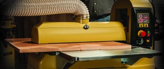
It is noteworthy that this device is often sold complete with a special vacuum cleaner that cleans work surfaces of industrial waste. Based on the technical and functional features of the machine, it is most often used in small enterprises, but it can also be found in home workshops.
It is worth noting that for home use this unit may be too powerful or too large.
Specifications
- Workpiece diameter. Above the bed - up to 150 mm, above the support - up to 90 mm.
- The length of the part in the centers is up to 250 mm.
- Cutter holder. Size – 8x8 mm.
- Drilling holes. Diameter - up to 8 mm.
- Inner spindle hole. Diameter 15 mm.
- The number of spindle rotation steps is 9.
- The spindle rotation range is from 200 to 3200 rpm.
- The length of the longitudinal movement of the caliper is 215 mm, the transverse movement is 90 mm.
- The longitudinal feed values are from 0.05 to 0.175 mm/rev.
- Machine weight 62 kg, dimensions: 690x410x230 mm.
During operation, the machine provides accuracy class “N” (normal). Cast iron bed. After casting it is subjected to natural aging.
The flat bed guide and the round guide installed in the bed serve as a common base for the spindle headstock, tailstock and longitudinal slide. A lead screw, covered with a protective casing, is mounted in the front part of the frame.
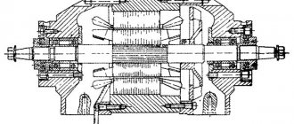
The headstock (often a spindle headstock) contains a spindle, at the front end of which thrust bearings are installed, operating under the influence of radial and axial forces. A 4-speed pulley driving the headstock shaft is mounted at the other end. There is also a mechanism (snaffle) installed here that changes the direction of rotation (reverse) of the propeller.
Machine drive. On the left wall of the headstock there is a bracket with an electric motor and machine drive mechanisms and an asynchronous machine motor with a power of 370 W, connected to a 220 V network with a frequency of 50 Hz.
Under the bracket assembly cover are located:
- stepped pulleys of the V-belt mechanism (9 rotation speeds);
- intermediate shaft with eccentric for adjusting belt tension;
- gear unit for the lead screw drive.
The feed mechanism (guitar) is designed to control the rotation settings of the lead screw through the gears in the bracket assembly.
The apron (the switching unit for the lead screw nut) is attached to the caliper carriage.
The caliper is used to move the tool holder. Comprises:
- carriages;
- cross slide;
- upper slide;
- tool holder assembly.
The tailstock is designed for:
- aligning the workpiece axis with the axis passing through the centers of the spindle and the centering mechanism of the tailstock;
- ensuring the rigidity of mechanisms during processing;
- securing drilling cutting tools;
- installation of moving and fixed centers.
Review of the Universal-2 lathe: types of main functions and characteristics
Moskovsky produces special equipment for working at home. The Universal-2 machine models are especially popular. Thanks to their design, they can perform a wide range of work on processing metal, wood and polymer workpieces.
Types of machine functions and its design
The main feature of the machine design is the function of changing the position of the spindle part relative to the bed. This makes it possible, in addition to standard turning operations, to perform a number of others using this equipment.
This is done with simple changeovers. To do this, it is necessary to study in detail the design and technical characteristics of the equipment. This versatility affects the processing parameters of materials.
At first glance, the layout of the machine is standard. The frame contains a slide, headstock and tailstock, as well as a drive with a gearbox. But to increase functionality, it is possible to change the position of the block with the spindle and power unit. After turning it 90°, the machine can perform drilling and milling.
List of operations performed on a desktop lathe after its modification:
- turning works;
- drilling and grinding;
- processing with a jigsaw and circular saw;
- jointing of wooden blanks;
- sharpening operations.
Converting the structure to perform these functions will not present much complexity. So, for drilling, it is enough to unscrew the mounting screws located on the protective cover of the spindle and the main drive. Then a vertical support is installed on the frame. A block with an electric motor and other components is mounted on it.
The standard equipment includes the necessary list of additional elements to perform the above operations. Their availability should be checked before purchasing the machine. This is especially true for purchasing used models.
Equipment Specifications
Main components of the equipment According to the passport data, the table-top lathe has good performance characteristics. They are due to a professional approach to creating a design. But despite this, the production association refused to produce such models, placing priority on the production of highly specialized machines.
The total weight of the equipment is 17 kg. At the same time, the dimensions of the machine do not exceed 66.5 * 35.2 * 22.7 cm. This design is intended for installation on a desktop. It does not provide level adjustment mechanisms
Therefore, during installation, you should pay attention to the level surface of the table.
The Universal-2 machine has the following technical parameters:
- maximum workpiece diameter. Above the bed – 12.5 cm, above the support – 6 cm;
- the length of the workpiece should not exceed 18 cm;
- drilling diameter when processing steel surfaces – up to 6 mm;
- height of the product when installed under a drill – up to 10 cm;
- the height of the cutter cannot be more than 8 mm;
- overall dimensions of the table. When working with a circular saw – 18*18 cm. When milling – 9*16 cm;
- maximum material thickness when sawing – 15 mm;
- permissible planing width – 3 cm;
- caliper offset. In the longitudinal direction - 16 cm, in the transverse direction - 6 cm.
To provide the main drive, the machine has a 0.25 kW electric motor. The rotation speed is 2600 rpm. The design provides for the possibility of forming metric threads. The limits of its steps range from 0.2 to 2 mm.
Examples of starting and servicing the machine can be found in this video:
stanokgid.ru
Features of the TSh 3M unit
The machine for turning and milling work, model TSH3, is made according to a classical layout. The list of functional units and parts includes:
- a frame that forms the rigidity frame of the unit;
- headstock with spindle clamping block;
- tailstock block with quill fixation unit;
- support for installing the main working body;
- electrical equipment unit.
The drive system includes an electric motor that transmits torque through a pulley. The connection diagram is standard: using a cable and a plug.
The engineering solution of the TSh 3M machine, which distinguishes it from other units of the same class, is the design of the bed. It includes metal sheets equipped with stiffening ribs, which made it possible to achieve optimal strength indicators with a low final mass of the unit.
Design Features
Compared to its predecessors, models TSh1, TSh2, the TSh3M machine received many additional components and technical measures designed to protect the operator and allow him to better control the working area and the quality of the operation being performed. The list of equipment features includes:
- shields made of transparent plastic, glass, protecting against the emission of chips and abrasives;
- work area lighting lamp with variable position;
- motor protective relay, blocking the transfer of power to the drive pulley wheel during overload.
The design is characterized by a high level of convenience, good visibility of the working area, comfortable positioning of the operator and the performance of various actions. This is achieved through a thoughtful arrangement of the functional units of the machine on the bed.
The design of the grinding head block has been modified. Installation of the working element is simple; in most cases, fixing it is enough to tighten one screw. However, to increase safety, each head is equipped with protective devices, and rigid positioning of the workpieces is carried out by the platforms of the working unit.
Specifications
The characteristics of the TS3 model are as follows:
- technological mass (machine without installed head block) - 220 kg;
- dimensions 660x600x1370 for height, depth along the drive block, width, respectively;
- seat diameter of wheels for grinding or sharpening - 127 mm;
- the maximum diameter of circles that can be used on the device is 400 mm;
- power supply 380V, three phases;
- electric drive power 3 kW;
- nominal cutting speed 20 mm/s.
The machine drive is equipped with a speed stabilization system and, under normal load, ensures rotation of the spindle chuck at a speed of 950 rpm.
Operating rules
The operating rules for the TSh3 machine include both a basic set of actions and some requirements determined by the design features of the equipment.
- The installation method and support for the machine must ensure rigidity and prevent displacement and resonant vibrations.
- Equipment grounding is mandatory.
- You should start working with parts only after the shaft has accelerated to the rated rotation speed.
- Installation of the machine in rooms with a designated level of explosion hazard, as well as when flammable substances are stored in them, is not allowed.
- The rests should not be installed higher than 10 mm of the directrix of the grinding wheel axis.
- The minimum gap between the workpiece and the abrasive wheel should not be less than 3 mm, and should not exceed half the thickness of the object.
When operating the machine, the list of mandatory measures includes (before its start-up) checking the grounding, the condition of the power cable and plug, the reliability of fastening of casings, working parts, and accessories. The serviceability is tested by starting the unit in idle mode for 5 minutes.
Personnel without special permission, qualifications, or profession are not allowed to work with TS3. The use of overalls (trousers, overalls with long sleeves and tightly buttoned cuffs), including a protective beret and glasses, is mandatory. Upon completion of the work, the dust collector, frame, and other structural elements are cleaned from dirt, dust, and metal shavings.
Universal – multifunctional table lathe. Purpose, scope
The Universal table lathe is a “hobby” class machine and is intended for individual (household) use, i.e., due to its design features and technical characteristics, the machine is not intended for use in production.
The Universal metal lathe is designed for processing workpieces made of metal, wood, and all types of plastic by turning.
The Universal machine is a desktop lathe and is intended for all kinds of turning work:
- grooving and boring of external and internal cylindrical, shaped and conical surfaces
- drilling holes, chamfering
- boring of holes
- segment
The spindle of the Universal lathe is a hollow steel part, with an internal hole of 10 mm for processing bar material, mounted on 2 roller bearings in the front and rear supports of the headstock.
The spindle receives 10 rotation speeds from a 120 W electric motor via a pulley drive. 4 speeds are obtained by rearranging the pulley belts between the 4-speed electric motor pulleys and the spindle take-up pulley. Other speeds are achieved by using an additional (intermediate) pulley.
The front end of the spindle of the Universal machine has an M20 thread for installation on the spindle of a lathe or driving chuck (see the article Lathe chucks).
A collet clamp with various internal holes can also be installed on the threaded end of the spindle.
In the drilling version, the spindle can move along its axis by 25 mm using a handle and a pair: gear wheel - gear rack. In the turning version, the spindle sleeve is clamped with two screws and is not used.
The support with the cutter installed on it moves along the longitudinal guides by 160 mm and along the transverse guides by 55 mm.
On the Universal machine, you cannot cut threads with a cutter because... there is no mechanical feed of the caliper - the lead screw is not connected to the drive and the caliper moves only manually.
On the “Universal” machine (Fig. 1), with the use of additional accessories and devices supplied with the machine, it is possible to perform a wide variety of types of machining on metal, wood, plastics and other materials.
A distinctive feature of the machine is its wide versatility and the possibility of readjustment using devices that allow you to perform the following work:
- turning and boring of holes;
- drilling holes
- milling of planes, recesses, grooves, etc.
- grinding and polishing
- sharpening of various cutting and household tools
- sawing sheet material, slats, boards using a circular saw
- sawing along the contour using a jigsaw
- coiling of springs
- thread cutting with dies and taps with manual rotation of the spindle to others
The machine operates from a single-phase alternating current network with a voltage of 220 V and a frequency of 50 Hz.
The “Universal” machine, when reconfiguring and installing additional devices, can have the following basic versions:
- turning version (Fig. 1);
- drilling, milling and grinding (Fig. 2)
- for working with a circular saw on wood (Fig. 3)
- for working with a jigsaw on wood (Fig. 4)
- sharpening
Currently, the Universal lathe has been discontinued and is no longer available. Instead, a more advanced tabletop lathe is being produced.
Universal series table lathes
The first model of the Universal table lathe with two round guides was developed by the ENIMS organization (Experimental Research Institute of Metal-Cutting Machine Tools). The basis was taken on the Unimat SL machine from the Austrian company EMCO (over 40 years, over 600 thousand machines of this model have been sold).
The Universal lathe was mass-produced at the Moscow Machine Tool Plant StankoKonstruktsiya.
Since 1968, the StankoKonstruktsiya plant began producing the Universal-2 table-top screw-cutting lathe - a significantly improved Universal machine.
In the second half of the 80s, the design of the machine was significantly redesigned: starting with the Universal-3 model, instead of two round guides, one of a larger diameter appeared in the middle of the bed and the headstock was no longer disconnected from the bed. Several factories began mass-producing the machine:
- : , , , , Minicurrent (SKT100-01, SKT100-02, SKT100-03).
- Michurinsky plant Progress: ,
- Orion SKTB Nizhny Novgorod:
- Penza Instrument-Making Plant (Federal State Unitary Enterprise FSPC “PO “Start” named after M.B. Protsenko”), Penza: TD-180, TN-150
Specifications
Main technical characteristics of the Kusok-3 machine:
- the diameter of the workpiece, which is mounted above the frame, is up to 43 cm;
- diameter of the workpiece installed above the caliper – up to 22 cm;
- the maximum length of the workpiece that is installed in the centers is 1 m, 1.5 m;
- spindle hole diameter – 41 mm;
- in the forward direction, the spindle rotates at a speed in the range of 16-3200 rpm;
- in the opposite direction the spindle rotates at the same frequency;
- the spindle has 21 forward and 21 reverse speeds;
- speed parameters of fast longitudinal movements 280 cm/min;
- cross feed range indicator – 004-4 mm/rev;
- longitudinal feed range – 0.08-8 mm/rev;
- the number of longitudinal feeds is 54 and the same number of transverse feeds;
- number of threads of all types cut – 54 for each;
- the cutting slides rotate to a maximum angle of ±90°;
- the cutting head contains 4 cutters;
- The quill moves maximum 16 cm.
The machine has medium dimensions:
- length – 262 cm;
- width – 99 cm;
- height – 126 cm.
The weight of the equipment without additional equipment is 2100 kg.
Principle of operation
How exactly TV 3 works is reasonable to consider based on the description of the kinematic diagram. The main functional movement is the rotation of the workpiece clamped in the headstock spindle chuck. Power transmission for this process is carried out from the main drive through a V-belt drive. In this case, it is possible to change the rotation speed by changing the gear ratio of the gearbox gears. The possibility of reverse rotation of the workpiece is also provided.
The second functional movement provided by the kinematics of the machine is working with a cutting tool. The approach to the processing zone can be carried out either manually, by rotating the corresponding wheel, or mechanically. For the latter, a feed box and a running roller are used. These two structural elements transform the cyclic rotation of the main drive shaft through a transmission device into a longitudinal/transverse, purely translational displacement of the caliper with a toolholder block.
The movement step of the caliper is regulated by the feed box by changing the gear ratio to select the required rotation speed of the lead screw. To change the depth of cut or the amount of material removed during turning, the mechanics of shifting the caliper tool holder in the transverse direction are used. This is achieved by using a sled design driven both mechanically and by a manual adjustment wheel designed for this purpose.
The TV3 machine allows you to cut threads manually by adjusting the position of the cutter with the corresponding feed wheels in the longitudinal and transverse directions. A mechanical method with transmission of torque from the main drive is also available. In this case, it is necessary to repeatedly pass the cutter over the workpiece. The mechanical cutting method shows much higher accuracy of work, with reduced requirements for personnel qualifications.
The TV 3 machine provides for installing a chuck on the tailstock quill cone. This allows you to cut internal and external threads using a wide range of taps and dies. Also, this functionality is convenient for drilling blind and through holes in workpieces and performing boring operations.
System and controls
Key control units are shown in the diagram.
- Handle for adjusting the feed movement. With its help you can activate the caliper and select the direction of its movement.
- Main movement adjustment knob. Activating the forward or reverse movement of the spindle stops its operation.
- Handle for moving the caliper (transverse).
- Handle for moving the tool holder.
- Handle for fixing the quill.
- Handle for moving the caliper (longitudinal).
Machine device
The unit is made according to a standard kinematic scheme. The design includes the following main elements:
- frame with fastening elements for all elements;
- headstock with spindle;
- tailstock;
- classic caliper;
- electrical equipment systems;
- controls (handles, handwheels, electrical buttons and switches);
- set of metal-cutting and grinding tools;
- protective equipment in the form of transparent shields;
- special backlight lamp;
- automatic shutdown system in case of emergency situations.
- some designs are equipped with a special vacuum cleaner (allows you to promptly clean the work area from production waste).
The TSH-3 lathe has a vertical layout and has relatively small dimensions and weight. This allows you to install it in a small room.
The bed has a cylindrical guide. Along it there is a smooth horizontal movement of the tailstock quill and perpendicular movement of the caliper.
The machine controls are:
- Spindle rotation control handle (it allows you to control the direction of rotation);
- Feed control system (it provides longitudinal feed of the caliper in both directions);
- Quill fastening clamp handle;
- Separate flywheels (to ensure movement of the following units: caliper, quill, cutter holder);
- Buttons for turning on and off the power supply for the entire unit.
The transmission of rotation from the electric motor to the spindle is carried out thanks to the main movement drive chain. For this purpose, it is equipped with a V-belt drive. The system provides nine possible rotation speed options. The range of their change varies from 200 to 1000 rpm. The position of the caliper is changed thanks to the so-called feed drive chain.
The electrical circuit of the TSh lathe is assembled in a separate box. It provides control of all electrical systems. To ensure safety, a system of protection against electric shock is provided. It belongs to the first class of protection.
Thanks to its universal equipment, the benchtop lathe is easy to operate. Even a person without relevant experience can carry out the necessary work on it.
Structural components of the machine and their characteristics
The classic assembly scheme is used. The functional cutter is controlled mechanically or manually. Starting and stopping are carried out using a special button.
Machine bed
The bed is a necessary connecting element of a lathe. Thanks to it, all nodes are securely attached to each other and can work together. In this case, the front part of the frame is the mechanism for moving the carriage, and the rear part is necessary for the operation of the tailstock. A rack and a lead screw are installed on the front side. The shape of the frame itself is box-shaped, there are two guides. The bed is kept in a constant position on two pedestals, which ensure the safety of using the TV 3 machine.
Headstock
The headstock has two main properties. The first is that it supports and prevents the part that is currently being processed from falling out of the unit. The second purpose is to impart rotational movement to the element, making processing possible. In TV 3, the headstock serves as a gearbox. The transmission of motion occurs according to the following algorithm:
- individual electronic carrier;
- spindle;
- first shaft;
- gear mounted on the first shaft;
- second shaft;
- several types of gears on the second shaft;
- third shaft;
- several gears on the third shaft.
The last block of gears engages with the blocks of the second ones and gives them movement. As a result, the blocks are transferred to the spindle of the main machine, which processes the element. In this case, this happens with the help of a washer that is installed on the thread of the device.
The rotational torque is transmitted several times and reaches the required size and power
The positioning and alignment of the gears on the multiple shafts is important, as they determine how much power is delivered. The gear ratio is determined by what the number of revolutions will be
Transmission mechanism
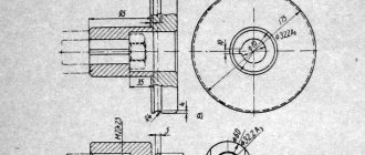
The mechanism is necessary for the transmission of torque from the gearbox to the gears. The caliper speed and pitch changes depending on the position of the gears. The transmission mechanism includes a bracket with the first roller of three gears (72 teeth), the second of four (42 teeth). The second shaft is engaged with the next gear (70 teeth), and the first with the gearbox. There is a formula that determines the size of the gear ratio: i = 24/72 * 42/70 = 1/5.
The number of gear ratios remains constant, since in the TV 3 lathe it is not possible to install gears with different technical characteristics and the number of gear teeth. The operation of the mechanism is dangerous; the student is protected by a layer of iron, which is installed in the form of a casing.
Gearbox
The box receives its torque from the transmission mechanism. At the same time, it is possible to set the caliper feed from 0.4 to 0.6, and the thread in increments from 0.6 to 1 mm.
Depending on the movement of the gear, the stroke of the roller changes. If the lever is placed to the left, then the clutch clings - the movement will be at the lead screw.
The gearbox is protected from external influences. Oil can be poured into the mechanism, when necessary, through special holes. The box is tightly attached to the frame.
Caliper
The support allows you to attach and move the cutter depending on the size, diameter and shape of the workpiece. The support on the TV 3 lathe has four carriages that drive the corresponding nuts and screws into operation. The caliper is a part that often wears out due to the appearance of a gap between the carriages. If problems arise, regulation is carried out using special bars.
Apron
The apron is designed to regulate the flow. By means of it, it is regulated, the work takes place using a lead screw, a roller, manually or mechanized. Manual and mechanical feeding are carried out using different methods. The first is using a flywheel on the second shaft, and the second is thanks to a sliding key.