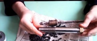
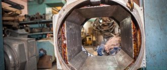
Serviceable rotor for Bosch angle grinder GWS6-100/GWS 850 MAX. Photo 220Volt
The rotor is one of the most complex structural elements of an angle grinder. At the same time, it is in a constant rotating state, which creates additional problems in maintaining normal operating conditions. Therefore, the reason for the malfunction of the angle grinder may be a broken anchor. However, you should not throw away such an angle grinder; you can actually do the repairs yourself . Rewinding failed reels is not such a difficult task and many people are quite capable of doing it.
Diagnostics
Before starting repairs, you should diagnose the failed angle grinder . This will allow you to determine the true reason why there were interruptions in the operation of the power tool and repair it at minimal cost. The electrical part of the angle grinder, which includes the rotor, is diagnosed according to certain rules using available instruments. Information on how to check the rotor for serviceability can be obtained from the link “Checking the continuity of the armature of an angle grinder with your own hands.”
Winding check
In most cases, the problem can be detected by its appearance and characteristic odor (see Figure 1). If the fault cannot be determined empirically, we proceed to diagnostics, which begins with a continuity test. If one is found, the engine is disassembled (this process will be described separately) and the connections are thoroughly inspected. When no defect is detected, a break can be established in one of the coils, which requires rewinding.
If the continuity test does not show a break, you should proceed to measuring the winding resistance, taking into account the following nuances:
- the insulation resistance of the coils to the housing should tend to infinity;
- for a three-phase drive, the windings must show the same resistance;
- For single-phase machines, the resistance of the starting coils exceeds the readings of the working windings.
In addition, it should be taken into account that the resistance of the stator coils is quite low, so to measure it it makes no sense to use devices with a low accuracy class, such as most multimeters. You can correct the situation by assembling a simple circuit using a potentiometer with the addition of an additional power source, for example a car battery.
Circuit for measuring winding resistance
The measurement procedure is as follows:
- The drive coil is connected to the circuit presented above.
- The potentiometer sets the current to 1 A.
- The coil resistance is calculated using the following formula: , where RK and UPIT were described in Figure 2. R is the resistance of the potentiometer, and is the voltage drop across the measured coil (shown by a voltmeter in the diagram).
It is also worth talking about a technique that allows you to determine the location of the interturn short circuit. This is done as follows:
The stator, freed from the rotor, is connected through a transformer to a reduced power supply, having previously placed a steel ball on it (for example, from a bearing). If the coils are working, the ball will move cyclically along the inner surface without stopping. If there is an interturn short circuit, it will “stick” to this place.
Steel ball testing
Required Tools
Multimeter Zubr. Photo 220Volt
To rewind the rotor windings, the following basic materials, tools and accessories .
1. Rewinding can be done in two ways :
- completely manually without the use of any equipment;
- Productivity increases greatly with the use of simple devices.
2. Multimeter or other instruments.
3. The user must be able to operate an electric soldering iron.
4. The presence of a winding wire, the diameter of which must correspond to the failed wire.
5. Electrical insulating cardboard or other similar material.
6. Sandpaper, textolite plates, soft wood and other materials for performing auxiliary work.
7. Epoxy resin or other impregnating varnish.
8. Other plumbing tools : hammers, a set of screwdrivers, hacksaw blades, sharp objects, such as a well-sharpened knife, chisels and other tools.
High-quality rewinding of electric motors at reasonable prices and in the shortest possible time.
Our prices and conditions will pleasantly surprise you. Our production workshops are equipped with modern equipment, measuring instruments and special stands for carrying out routine repairs of motor windings for any problems:
- general aging of insulation due to long-term use;
- unsatisfactory condition of insulation of stator winding elements due to numerous mechanical deformations or damage;
- loosening of the winding fastenings;
- re-mixing of stator active steel.
- lack of connecting circuits
In the latter case, our specialists are able to calculate the winding connection diagram independently.
Laying diagram, winding Interskol 230, Makita 9558HN or 9558BN and other models
The order of winding the rotor windings depends on the number of slots in the rotor core and the commutator lamellas. The parameters that determine the location of the winding wire on the rotor include winding direction and pitch . The rotation of the spindle shaft (right or left) is precisely related to the choice of which direction the wire is laid. When performing rotor repairs, it is necessary to record the above data of the burnt winding.
Important : visually identify the topmost coil and start unwinding the end from it in order to determine the layout of the winding wire. Maintaining the old pattern is a determining factor in successful anchor repair.
The number of turns and the diameter of the wire are fixed after removing the front part of the failed winding, which will allow you to carefully remove the complete bundle of wire located in the groove.
Most of the used grinders, regardless of the model (Interskol, Makita and others), are structurally made with 24 slats and a core with 12 grooves. The winding pitch is chosen to be 6.
12 grooves and 24 slats
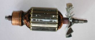
Rotor for INTERSKOL USHM-2300M, HAMMER. Photo 220Volt
The rotor winding with such design parameters is performed as follows.
- The direction of the winding is set (usually clockwise when viewed from the commutator side).
- Insulation made of electrical cardboard and other similar material is installed in the cleaned grooves . The winding wire is soldered to lamella No. 1 in accordance with the old installation scheme.
- The wire is placed in groove No. 1 opposite the lamella indicated by the first number and, according to the winding pitch, is directed into groove No. 6 and returning back. The number of such layings corresponds to the size of the winding turns.
- A circuit with 12 grooves and 24 lamellas is built after soldering the middle of the winding to lamella No. 2 and continuing to wind the winding wire into the same groove. The required number of turns is maintained and soldering is carried out to lamella No. 3. This is how the first complete reel is obtained.
- Next, winding is carried out in slots No. 2 and No. 7 , soldering the middle of the winding to lamella No. 4 and the end of the winding to lamella No. 5.
- By winding the coils using the above method, the last of which ends on lamella No. 1, all 12 grooves and 24 lamellas will be involved in the laying pattern.
How to quickly check the commutator motor mechanism for malfunction
Checking the element - armature , which is the main part of the commutator motor, is carried out in stages. To carry out performance testing, you need to prepare a screwdriver and a multimeter. Monitoring your condition at home can save you money.
Nuance: To improve the quality of checking the armature winding for a faulty commutator motor , it would be a good idea to buy an inexpensive device. The latter allows for in-depth monitoring of the armature core .
The initial stage is a thorough visual inspection of electrical equipment. There are situations when electrical equipment still works, but with deterioration in nominal characteristics. The latter may be a consequence of an interturn short circuit ; the result is that the part “burns.” This is easy to determine - you don’t even need to disassemble the case.
Some signs, but not the main ones, are:
- strong sparking during operation of the electric motor - noticed on the traction motor commutator ;
- The startup of an electric tool is accompanied by a voltage drop in the power supply network - the lighting begins to flash. Can lead to a short circuit in the entire facility;
- when trying to start the electric motor, sharp jerks appear;
- burnt smell of winding mechanism;
- the tool cannot reach its rated power.
But it is worth noting that the above-mentioned signs show not only a breakdown of the armature of the collector unit - the engine . All of the above may indicate mechanical and electrical wear of the motor assembly brushes. Worn out, collapsed brushes are the main cause of power plant failure. Replacing them with new ones and cleaning the unit from plaque will extend the service life of power equipment.
When examining the part, there should be no traces of burning, paper, or blackening on it. The mentioned nuances are consequences of a short circuit or combustion. Prolonged presence of dust and dirt provokes a deterioration in the performance of the entire installation as a whole. Therefore, the aspect of cleanliness and maintenance must be given due attention, otherwise:
- premature wear of elements increases - scale and carbon deposits negatively affect the quality of work;
- the resistance of the internal parts of the electrical unit to negative environmental influences decreases.
Is the brush mechanism intact? Then the fault lies in the CD mechanism. But there are situations in which a power tool does not show signs of life - it does not start, does not react in any way to an attempt to turn it on. Let's move on to the next stage.
Complete dismantling of the tool body and disassembly
If the brushes are in order, but the cause of the breakdown cannot be determined, then disassembly of the electrical equipment will be required. The problem may lie in the internal parts of the commutator motor. First you need to pick up a screwdriver - a licked thread will not bring anything good.
The equipment has fasteners of various sizes. In order not to make a mistake, you need to remember, or better yet, sketch the bolt placement diagram. For better memory, you can take photographs of each stage of the work. This will prevent problems with the assembly of the power tool.
Household electrical appliances do not always have a complex design, and therefore the disassembly process is not particularly complex, which cannot be said about industrial electrical installations. Technical diagnostics and repair of the latter require advanced qualifications of specialists and the availability of professional testing equipment.
Preliminary preparation of the collector armature
Completed dismantling is not the final operation. The element must be prepared for further inspection. Preliminary measures will ensure the highest quality diagnostics of the component. This procedure is simple and consists of completely cleaning the slats from plaque.
The fact is that during active use, particles of work products accumulate on the surfaces of parts. This is especially true for electric motors that have been used for a long time. Plaque prevents the correct passage of current and load distribution throughout the collector complex.
Preparation is optional. But it will improve the quality of the result. Cleaning involves the use of rags and an alcohol solution. Removal of carbon deposits occurs through the action of fine-grained sandpaper. Do it carefully - any remnants of an abrasive tool will aggravate the situation with the performance of the commutator motor. Therefore, after removing carbon deposits, you need to remove traces of abrasive action with sandpaper.
Note : The mechanism must be cleaned carefully without damaging the winding . The ingress of abrasive particles and broken lamellas are aspects that increase the likelihood of an interturn short circuit in a commutator motor.
Complex processing
Processing of composite shafts is carried out in strict compliance with the second class of accuracy. The final operation is additional grinding, which does not allow the presence of transverse scratches or burrs. The mentioned abrasives significantly damage the integrity of the surface layer of the shaft.
Close attention is paid to the transition fillets - they need to be polished to a shine. This ensures uninterrupted operation of both the individual device and the entire installation as a whole. The coefficient of compression of the surface of the shaft and bushing is also reduced - necessary for an accurate fit of the anchor bushing to the shaft. In connection with the latter, diameter ledges are made along the seats.
Visual inspection before testing
Here you need to carefully inspect the manifold and the CD part. If the latter has significant depletion, then repair will not help, only replacement is relevant. The presence of a large accumulation of carbon deposits on the windings of the device and its contacts is a sign of a deep malfunction of the part. There are several ways to solve this. The first is complete rewinding, according to the winding diagram of the armature of the commutator mechanism - the engine . It will take a long and painful time to do, and the second is installing a new part. The choice is, of course, yours.
Fast and high-quality inspection - emphasis on specific details, allowing you to comprehensively determine the breakdown of elements. Pay attention to elements such as:
- collector lamellas are parts on which carbon deposits often accumulate. Constant contact wears them out, and therefore if there is significant wear, there is a high probability of further motor failure;
- armature windings – breaks, traces of interturn short circuit and conductor burning;
- contact elements of the power unit - windings are connected to the lamellas by soldering. These places must be carefully checked for integrity. Breakdowns of contacts are fraught with deterioration in the performance of the electric motor.
After completing the visual inspection of the part, you can begin using the diagnostic equipment.
Monitoring performance with a radio multimeter
The use of a measuring device is a mandatory aspect. Without it, alas, it will be almost impossible to correctly determine the problem and the cause of the malfunction. Directly using a multimeter is divided into several stages, usually there are two. The first involves checking for the presence of a breakdown. How it's done:
- The device is set to check the electrical circuit, accompanied by a sound indication;
- one probe of the device acts on each part, and the second – on the body of the power element.
The second stage involves measuring the resistance that arises between adjacent windings. This is done very easily - the multimeter is set to resistance detection mode at the minimum range - usually set to 200 Ohms. Probes are the contact parts of a radio-technical device and are placed on the lamellas of the commutator.
The device reads the resistance parameters and transfers them to the screen. Next, the measured characteristics are recorded (it is better to write them down so as not to forget). The resistance should be the same between all lamellas. If this is not the case, then the commutator motor mechanism is faulty. Lack of resistance is a factor confirming a performance problem.
Diagnostics for determining interturn short circuit (MF)
One of the main causes of breakdowns is a short circuit between the turns. It is formed due to increased load on the motor, exceeding the maximum permissible parameter. The windings of the stationary mechanism - the stator - heat up, the increased temperature conditions trigger degenerative insulation processes, and as a result, MF occurs. Incorrect operating specifications lead to a significant increase in the load on the equipment.
Tip : Before using the motor, read the passport information. It indicates acceptable parameters under which the application will not have a destructive effect.
Excessive load is formed due to breakdown of the mechanical part. Bearings often jam, which leads to short-circuiting of the armature coil turns. This problem may arise due to manufacturing defects or be a consequence of poor-quality repair work.
Determine MH:
- check the stator temperature - uneven heating confirms a breakdown;
- measure the load of each phase. The difference may be a sign of a broken element.
As in the case of continuity testing, the MH is checked with a multimeter or megger. There is a more accurate method - using a transformer using step-down technology:
- Three phases of the transformer are connected to the stator;
- Next, the ball is thrown into the stator. If the ball runs in a circle, then everything is fine, if not, it is magnetized - a short circuit.
Instead of a ball, a plate is used. In the place where the MS occurs, vibration occurs. If the armature is working properly, the element is simply magnetized to the iron. Don't forget about grounding.
The MF is easily determined using a specialized device, which is a transformer with a cut-out core. Placement in the slot causes the component to function as a secondary winding. During an interturn short circuit, the plate located at the top vibrates or is magnetic to the body. After eliminating the problem, it is necessary to re-check using the above method.
Replacing the anchor yourself at home
Practice shows that if you decide to replace the armature of an angle grinder, then it is best to change it together with the support bearings and the engine cooling impeller.
To replace you will need:
- New angle grinder anchor. Must match your model. Interchange with other models is not permitted.
- Screwdrivers, wrenches.
- A soft brush and cloth for wiping the mechanism.
How to remove an anchor
Replacing the anchor begins with disassembling the angle grinder. The following steps are performed:
- Use a screwdriver to unscrew the brush units on both sides. The brushes are removed.
Video: replacing bearings on an angle grinder
How to put an anchor in place
To install a new angle grinder anchor in place, you should take a new part, and then assemble the tool in the reverse order. The sequence of actions is as follows:
- A fixation disk is installed on the armature shaft.
- The bearing is installed using the pressing method.
- The small gear is fitted and secured with a retaining ring.
- The anchor is inserted into the gearbox housing, and the docking holes are aligned.
- The gearbox mounting bolts are tightened.
- The anchor with the gearbox is inserted into the body of the angle grinder and fixed.
- The brushes are deposited in their places and closed with lids.
After completing these steps, the grinder is ready for work. The anchor has been replaced.
Video: how to check an angle grinder
An ancient Sufi wisdom says: “A smart person is one who is able to come out of a difficult situation with dignity. But the one who does not find himself in such a situation is wise.” By following the rules for operating household appliances and preventing the motor from overheating, you can avoid breakdowns and troubles in the operation of the angle grinder. Keeping and storing the tool clean and dry will prevent its mechanisms from contamination and oxidation of current-carrying elements. Timely maintenance of the tool is guaranteed to eliminate unpleasant surprises during operation.
Features of repair of commutator drives
This type of electric machine is more likely to experience mechanical failures. For example, brushes worn out or commutator contacts clogged. In such situations, repairs come down to cleaning the contact mechanism or replacing graphite brushes.
Testing the electrical part comes down to checking the resistance of the armature winding. In this case, the probes of the device are applied to two adjacent contacts (lamellas) of the collector, after taking readings, measurements are taken further in a circle.
Checking the armature winding of a commutator motor
The displayed resistance should be approximately the same (taking into account the instrument error). If a serious deviation is observed, then this indicates that there is an interturn short circuit or open circuit, therefore, rewinding is necessary.
Soldering the collector plates
The slats are installed on a plastic base. They are usually erased to the very base. Only the edges remain that the brushes cannot reach.
Such a collector can be returned by soldering.
- Cut the required number of lamellas to size from a copper pipe or plate.
- When the armature of copper residues, solder it with ordinary tin and soldering acid.
- When our client is left with the lamellas soldered, do some sanding and polishing. If you don't have a lathe, use a drill or screwdriver. Insert the armature shaft into the chuck. Sand first with ratfil. Polish later with fine sandpaper. Don’t forget to clean the grooves between the slats and measure the resistance.
- There are lamellas that are not completely damaged. To return them, you need to carry out more painstaking preparation. Lightly grind the commutator to clean the records.
Source
How to repair an anchor at home
A third of screwdriver failures occur due to the anchor. With everyday intensive operation, malfunctions can occur within the first six months, for example, if the brushes are not replaced in a timely manner. With gentle use, the screwdriver will last a year or more.
The anchor can be saved if the balance is not disturbed. If during operation of the device you hear an intermittent hum and there is strong vibration, then this is an imbalance. This anchor must be replaced. And the winding and commutator can be repaired. Small short circuits are eliminated. If a significant part of the winding is damaged, it can be rewound. Worn and badly damaged lamellas should be sharpened, extended or soldered. In addition, you should not undertake anchor repairs if you are unsure of your capabilities. It is better to replace it or take it to a workshop.
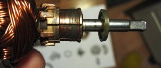
Collector groove
Over time, wear from the brushes forms on the commutator. To get rid of it, you need to:
- Grind the commutator using cutters for longitudinal grinding, that is, through cutters.
Passing straight cutter
Don't forget to clear the rotor of chips to prevent a short circuit.
Do-it-yourself static balancing of the electric motor armature
The key to uninterrupted operation of the equipment after rewinding the armature is proper balancing. In large electric motor repair companies, dynamic balancing is done on a special machine. Since it is difficult to rewind the anchor yourself for the first time, the device for static balancing “On Knives” will help to identify gross errors. It is easy to design it yourself.
Pick up two steel blades. They must have good straightness and cleanliness. Place the blades on a rigid base parallel to each other. The distance between the blades is the size of the anchor. The result should be something like this:
Schematic representation of the “On Knives” device, where 1 is the armature of the electric motor; 2 — steel blades; 3 - base; A and B are points for soldering weights.
The balancing method is simple: the anchor is placed on the blades and its movement is observed. The anchor will rotate because the heaviest part will be at the bottom. The task is to move the center of gravity as close as possible to the axis of the anchor, which is indicated by the dotted line. With high-quality balancing, the anchor remains motionless. To equalize the weight, plasticine weights are hung on points A and B. When equilibrium is achieved, the weights are removed, weighed, and metal equal to their weight is soldered.
Now you know how to rewind an anchor with your own hands. Thanks to balancing skills, your instrument will not vibrate and overheat, even with minor flaws in the winding installation. Regular checking of contacts and routine cleaning of the housing will help minimize the likelihood of equipment breakdown.
DIY armature rewinding diagram
Development and production of servos, brushless and valve motors, propulsion (traster) for remotely controlled uninhabited underwater vehicle (ROV, ROV)
44. DIAGRAMS OF MANUAL ANCHOR WINDINGS
Among the manual windings used for anchors, three types can be distinguished: simple manual, herringbone and skirt.
The herringbone winding is also sometimes called double-chord, since its sections are divided into two equal parts (two half-sections), forming two chords in end view, diverging from one groove. The number of sides of the section in the armature groove with manual winding can be equal to two (with u
n = 1) and more (for
u
n = 2 or more).
Rice. 98. Simple manual winding at u
p=1:
a -
winding the first section and forming a loop for winding the second section,
b
- winding the second section,
c
- working diagram,
d
- end view;
1 - start of winding, 2 - first section, 3 - second section, 4
- first loop, 5 - second loop
Simple manual winding at u
n=1 is wound as follows.
2
is wound (Fig. 98, a), then a loop
4
to connect to the collector, after which the second section (Fig. 98,
b, d)
is wound into adjacent grooves, a loop 5 is made, etc. When on four sides in the groove (
u
p = 2), the second section is wound into the same grooves as the first (Fig. 99), and the loops for connecting to the collector are made after winding each section.
When winding in a herringbone pattern, each section is divided into two half-sections. First, wind the first half-section of the winding (Fig. 100, a), then move to the next step groove (7th groove in Fig. 100, b
) and wind the second half-section
4.
After formation
loops 5 wind the following sections in the same way. When u
n=2 the second section is wound into the same grooves as the first.
The number of turns in a half-section when winding in a herringbone pattern is determined by dividing the total number of turns in the groove by 4 u
p
.
For example, with the total number of turns in the groove 72 and
u
p = 2, the number of turns in the half-section
Working diagrams of herringbone windings at u
n=2 are shown in Fig. 101. When bevelling the grooves of the armature package, the marking of manual windings, as well as template ones, is made along the middle section of the package.
Rice. 99. Simple manual winding at u
n
=2: a
- winding the first section and forming a loop for winding the second section, b - winding the second section,
c -
working diagram,
d
- view from the torp;
1
- start of winding,
2
- first section,
3
- second section,
4
- first loop,
5
- second loop
Skirt winding is used with a small number of turns in a section (usually no more than three). To wind it, pieces of wires are cut off from the coil in advance, the number of which should be equal to the number of sections. The length of each piece of wire should be equal to the unfolded length of the section. The ends of all cut wires 2 (Fig. 102) are placed in the collector plates 1, the wires are bent and placed in grooves in accordance with the winding diagram. Upon exiting the groove on the side opposite to the collector, all the wires are simultaneously bent again, and a bandage 4 made of stocking is placed on them to secure them. Then, on the side opposite to the collector, the wires are bent around the bandage 4 ,
form the frontal part, after which they are placed in the grooves in accordance with the winding pitch along the
Rice. 100. Manual herringbone winding: a
- winding the first half-section and the transition for winding the second half-section,
b
- winding the second half-section and forming a loop,
c -
working diagram,
d
- end view;
1
- start of winding,
2
- first half-section,
3
- transition to the second half-section,
4
- second half-section, 5 - loop
Rice. 101. Working diagram of the herringbone winding at and
p
= 2: a -
without bevel of the grooves,
b
- with bevel of the grooves by 1/2 of the groove division
the top of the first layer wires already there. This creates a loop 3
(skirt) on the side opposite to the collector, and the first turn is formed.
To obtain the second turn, the wire from the collector side is bent and secured with a bandage 5
and again placed in the same grooves with bending and securing the frontal part with a new bandage on the opposite side. Bending and bandaging operations are repeated
Rice. 102. Skirt wrap: 1
- collector plate,
2 -
wires,
3
- loop,
4, 5
- bands
They ring as many times as there are turns in the section. After winding all the turns, the ends of the wires are placed in the slots of the commutator in accordance with the winding diagram.
The number of loops (skirts) of the winding on the side opposite the collector is equal to the number of turns, and on the side of the collector - one less.
Skirt windings are made both as loop windings and as wave windings. Their circuits are no different from ordinary template windings.